VT-VETSY-1-1X/1-1-0-A-0
Rexroth
R978911933
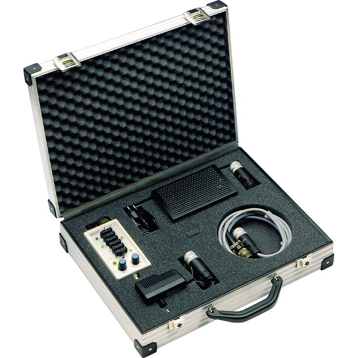
维修工具箱:测试装置、24 V电源单元、连接电缆及适配器。
测试装置适用于控制和功能测试带集成电子装置、工作电压为±15 V或+24 V的比例伺服阀,可简化相关液压系统的调试与故障排查。
01 | 02 | 03 | 04 | 05 | 06 | 07 | 08 | |||||||
VT-VETSY-1 | – | 1X | / | 1 | – | 2 | – | 1 | – | 1 | – | 0 | / | * |
01 | Service case with test device for proportional servo valves with integrated electronics | VT-VETSY-1 |
02 | Component series 10 ... 19 (10 ... 19: unchanged technical data and pin assignment) | 1X |
03 | Test device type VT-VET-1-1X | 1 |
Connection cable to valve | ||
04 | 2 units, 6-pole, type VT-VETK-1-1X | 2 |
Adapter cable for valve type 4WSE2EM 6 -1X | ||
05 | Type VT-VETAK-1-1X | 1 |
Power supply unit | ||
06 | 90 … 264 VAC; +24 VDC, 3.75 A; type VT-VETNT-3-1X/G24 | 1 |
07 | Without power supply unit | 0 |
08 | Further details in the plain text | * |
Ambient temperature range | °C | 0 … +50 |
Dimensions (W x H x D) | mm | 94 x 54 x 160 |
Weight | kg | 0.36 |
Conformity | CE according to EMC directive 2014/30/EU, tested according to EN 61326-2-1 and EN 61326-1 RoHS directive 2011/65/EU |
Operating voltage | Switch “power selector” | Switching position “24 V” | V | 24; –20 % +40 % |
Switching position “±15 V” | V | ±15; ±10 % | ||
Current consumption of the test device | A | 0.1 | ||
Protection class according to EN 60529 | IP20 | |||
Input connector ES | Command values at pin E and D | according to the valve specifications | ||
Enable signal at pin C (24 V operation) | Not active | V | 0 … 10 | |
Active | V | 16 … UB | ||
Output socket AB | Actual value at pin F | according to the actual value output of the valve | ||
BNC socket | V | 0 … ±10 | ||
Input connector ES | Actual value at pin F | according to the actual value output of the valve | ||||
Output socket AB | Enable signal at pin C (24 V operation) | "setpoint selector" switch; "internal" or "BNC" spool position; "enable" enable switch | In switching position “off” | V | 0 | |
In switching position “on” | UB | |||||
"control" spool position; "enable" enable switch | In switching position “off” | V | 0 | |||
In switching position “on” | according to pin C of the input connector ES | |||||
Command values at pin D and E | "setpoint selector" switch | Switching position “internal” or “BNC” | Pin E | Reference potential | ||
Pin D | V | 0 … ±10, if Re valve >500 Ω | ||||
mA | 0 … ±20, if Re valve <500 Ω | |||||
"control" spool position; "enable" enable switch | Pin E and D | according to the input connector ES (pin E and D) | ||||
测试装置适用于控制和功能测试带集成电子装置、工作电压为±15 V或+24 V的比例伺服阀。
运行模式
外部运行 → 将控制柜的工作电压和指令值接入阀
内部/外部运行 → 通过测试仪预设指令值;工作电压由控制柜提供
内部运行 → 通过独立电源装置提供工作电压;通过测试仪预设指令值
通过 BNC 插座预设指令值 → 工作电压可选
注意:
测试装置仅可由熟悉装置、阀及液压系统的人员使用。采用相应设置时,装置会忽略系统控制信号,从而使控制侧原有安全防范失效。
对于操作不当造成的损坏,不承担责任。
根据阀所需工作电压,测试装置可采用+24 V或±15 V供电。调试前必须相应设置“power selector”电源选择开关。
内部 DC/DC 转换器产生所需的 ±15 V 辅助电压,供内部指令值预设使用。
“power selector”电源选择开关还会将内部参考电位L0切换至相应的外接地电位。
开关位置“+24 V”→ 输入插针 B = 参考电位
开关位置“±15 V”→ 输入插针 C = 参考电位
连接
输入接头 ES(1)及 4 mm 输入插孔:左侧输入接头 ES(1)用于连接来自控制器或控制柜的电缆。根据操作元件的设置(参见操作及显示元件),左侧 4 mm 插孔直接连接至输入接头 ES(1)的插针,因此可在插孔处测量控制器输入的全部信号。测试仪和阀运行时,必须具备所需的 +24 V 或 ±15 V 工作电压,具体取决于阀型。若控制柜侧尚未提供工作电压,可在输入接头 ES 处连接相应电源装置。
输出插座 AB(16)及 4 mm 输出插孔:右侧输出插座 AB(16)用于连接阀。右侧 4 mm 插孔直接连接至输出插座 AB(16)的插针,因此可在插孔处测量所有往返于阀的信号。借助短接插头,可分别断开连接电缆中的任一导线,例如用于测量电流。
BNC 插座:可通过标准 50 Ω 电缆将外部产生的指令值信号输入 BNC 插座。此时,指令值选择开关“setpoint selector”应置于“BNC”位置。
PE 插孔:PE 插孔直接连接至输入接头 ES(1)的 PE 端子。输出插座 AB(16)不设 PE 连接。
Position | Functional element | Lettering |
1 | Input connector ES: connection on the control side via connector K31, CM02E14S‑61P | – |
2 | Switch for selecting the operating voltage required by the valve | power selector |
LED displays | ||
3 | Ready for operation | power |
4 | Enable signal of the input connector ES and from the external control at pin C | enable indication control |
5 | Input measuring sockets | A … F and PE |
6 | Switch for the selection of the command value signal source | setpoint selector |
7 | BNC socket for connecting an external, independent command value encoder | – |
8 | Potentiometer for setting the internal command value signal | setpoint intern |
9 | Shift key between the internal command value signals for generating a step signal | stepfunction key |
10 | Enable switch for generating an enable signal independent of the external control | enable |
11 | Trimmer for the amplitude adjustment of the internal step function generator | stepfunction level |
12 | Output measuring sockets for controlling the signals on the valve connection cable | A … F |
13 | Enable signal at measuring sockets, output socket AB and pin C | enable indication valve |
14 | Short-circuit bridges for separating individual cable wires of the connection from control to the valve | – |
15 | Designation for measuring sockets A … F | A … F |
16 | Output socket AB: valve-side connection via flange socket MS3108A-14S-6S | – |
17 | Current/voltage output for valve command value with automatic switch-over between UA = 0 V … ±10 V oder IA = 0 … ±20 mA | – |
18 | Voltage converter DC/DC for the internal voltage supply | – |
注意事项:
不带使能输入的运行模式:采用集成电子装置、工作电压为 +24 V 且无使能输入的阀,以 C 端子作为阀实际值的参考电位。此时,“enable”使能开关应置于“off”位置。
带使能输入的运行模式:采用集成电子装置、工作电压为 +24 V 且带使能输入的阀,以 B 端子作为阀实际值的参考电位。此时,“enable”使能开关应置于“on”位置。
Pin | "+24 V" | "±15 V" |
A | +24 V | +15 V |
B | 0 V | -15 V |
C | Enable or reference potential for the actual valve value, e.g. with type 4WRSE | 0 V |
PE | Protective ground | Protective ground |
D | Command value + | Command value + |
E | Command value – | Command value – |
F | Actual value | Actual value |
各项目的说明参见“产品描述”。