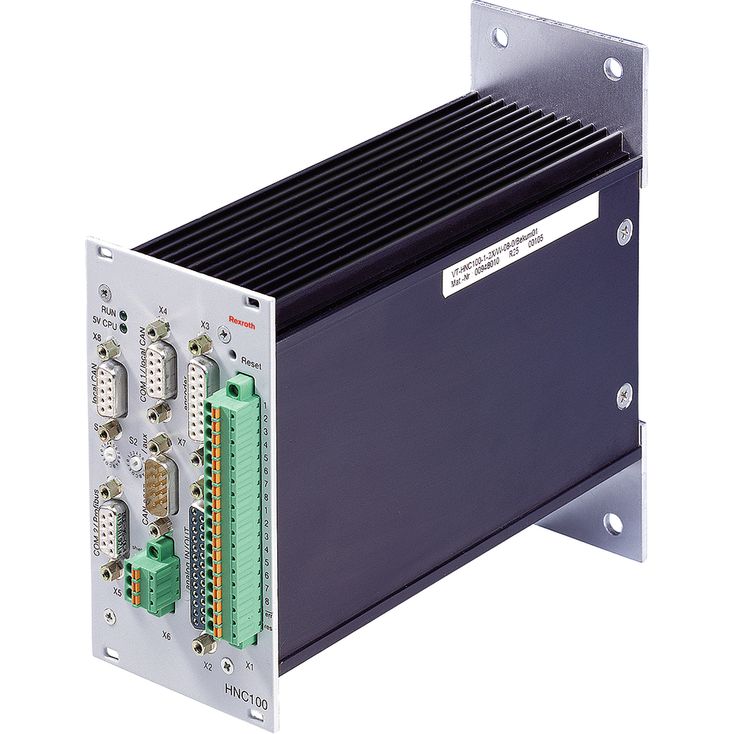
HNC100数字轴控制器是用于单根受控轴的可编程数控装置,满足液压驱动闭环控制的专门要求,也可对电气驱动进行闭环控制。
针对恶劣工业环境设计,可抵抗干扰、机械振动、冲击及气候影响。
01 | 02 | 03 | 04 | 05 | 06 | 07 | 08 | ||||||
VT-HNC100 | \u2013 | \u2013 | 2X | / | \u2013 | \u2013 | \u2013 | 0 | * |
01 | Digital NC control HNC100 | VT-HNC100 |
02 | Version for 1 hydraulic axis | 1 |
Versions for 2 hydraulic axes | 2 | |
03 | Component series 20 ... 29 (20 ... 29: unchanged installation and connection dimensions) | 2X |
Installation type: | ||
04 | Housing for wall mounting | W |
Housing for rack mounting | M | |
05 | For 1-axis version: | |
8 digital inputs/outputs | 08 | |
24 digital inputs/outputs | 24 | |
For 2-axis version: | ||
16 digital inputs/outputs | 16 | |
06 | Without bus connection | 0 |
PROFIBUS DP 1) | P | |
CANopen | C | |
INTERBUS-S | I | |
07 | without evaluation electronics | 0 |
08 | Further details in the plain text | |
| 1) The additional connector type 6ES7972-0BA41-0XA0 for PROFIBUS DP is not included in the scope of delivery and has to be ordered separately! Material no.: R900050152 |
Component series | 2X |
Operating voltage | UB | 18 to 36 VDC | |
Power consumption 1) | Pinternal | W | 8 |
| 1) | additional power for connected sensors/actuators |
Voltage inputs (differential inputs) | Channel number | 4 | ||
Input voltage | UE | +10 V to \u201310 V measurable (max. +15 V to \u201315 V) | ||
Input resistance | RE | 200 kΩ ±2 % | ||
Resolution | 5 mV | |||
Non-linearity | mV | < 10 | ||
Calibration tolerance, max. 1) | max. 40 mV (with factory settings) | |||
Current inputs | Channel number | 4 | ||
Input current | IE | 4 mA to 20 mA | ||
Input resistance | RE | 100 Ω ±0.2 % | ||
Resistance between pin "Iin 1 \u2012" and "analog_GND" | 0 to 500 Ω | |||
Leakage current | Iv | 0.1 to 0.4 % (at 500 Ω between pin "Iin 1 \u2013" and "analog_GND") | ||
Resolution | 5 μA | |||
Impedance inputs | Channel number | 4 | ||
Input voltage | Uimp | -10 V to +10 V | ||
Input resistance | Rimp | 100 Ω ±0.2 % | ||
Resolution | 5 mV for range ±10 V, 2.5 mV for range 0...10 V | |||
Non-linearity | < 10 mV | |||
Calibration tolerance, max. 1) | 40 mV (with factory settings) |
| 1) | If the factory settings are insufficient, the measurement technology can be calibrated on site via software in a system-specific way. |
Switching inputs | Number | 8 16 24 | |
Logic level | log 0 (low) ≤5 V; log 1 (high) ≥10 V to UB; Re = 3 kΩ ±10 % | ||
Connection | flexible conductor up to 1.5 mm2 |
Voltage outputs | Channel number | 4 | |||
Output voltage, normalized | Unorm | \u201310 V to +10 V (max. \u201310.7 V to +10.7 V) | |||
Output current, max. | Imax | 10 mA | |||
Load, min. | Rmin | kΩ | 1 | ||
Current outputs | Channel number | 2 | |||
Output current | normalized | Inorm | 4 mA to 20 mA | ||
non-normalized, max. | Imax | mA | 23 | ||
Load, max. | Rmax | Ω | 500 | ||
Residual ripple | ±60 mV (without noise) | ||||
Resolution | 1.25 mV | ||||
Non-linearity | in the range \u20139.5 V to +9.5 V | mV | 15 | ||
in the range \u201310 V to \u20139.5 V and +9.5 V to +10 V | mV | 35 | |||
Switching outputs | Number | 8 16 24 | |
Logic level | log 0 (low) ≤2 V; log 1 (high) ≤ UB; Imax = 50 mA | ||
Connection | flexible conductor up to 1.5 mm2 |
Incremental transducer with TTL output | Input voltage | log 0 | 0 to 1 V | |||
log 1 | 2.8 to 5.5 V | |||||
Input current | log 0 | -0.8 mA (with 0 V) | ||||
log 1 | 0.8 mA (with 5 V) | |||||
Frequency, max. related to Ua1 | fmax | kHz | 250 | |||
SSI transducer | Coding | Gray code | ||||
Data width | adjustable up to max. 28 bit | |||||
Line receiver (TTL) | Input voltage | log 0 | 0 to 1 V | |||
log 1 | 2.8 to 5.5 V | |||||
Input current | log 0 | -0.8 mA (with 0 V) | ||||
log 1 | 0.8 mA (with 5 V) | |||||
Line driver | Output voltage | log 0 | 0 to 0.5 V (at 120 Ω) | |||
log 1 | 2.5 to 5.5 V (at 120 Ω) | |||||
Voltage supply of position transducers via HNC100 | U | UB or +5 VDC ±5 %; max. 200 mA | ||||
Voltage for all input signals, max. | Umax | UB \u20131 V (the signals are not opto-decoupled) | ||||
Inductive position transducers | Quantity | 2 | ||||
Voltage supply | Ueff | 2 V (Imax = 30 mA / channel) balanced to earth, short-circuit-proof, synchronizable between 4.8 and 5.2 kHz, optional compensation capacitor of 220 nF; amplitude constancy ≤ 0.2 % /10 K; carrier frequency 5 kHz ± 2 %; inductive transducers in half and full bridge circuit and 3 and 4-line circuits; linearity error < 0.1 % | ||||
Processor | 16/32 bit MC68376 | |||
Accumulators | Flash-EPROM 1 MB; EEPROM 8 KB; RAM 256 KB (RAM) | |||
Serial interfaces | Standard | RS232 (9.6 KBaud) | ||
optional | PROFIBUS DP (max. 12 MBaud) CANopen, INTERBUS-S | |||
Reference voltage | Uref | +10 V ±25 mV and \u201310 V ±25 mV (20 mA each) | ||
Storage temperature range | ϑ | °C | -20 \u2026 +70 | |
Weight | VT-HNC100-1-2X/.-08-.-. | m | kg | 1 |
VT-HNC100-2-2X/.-16-.-. and VT-HNC100-1-2X/.-24-.-. | m | kg | 1.2 | |
模拟输入:不能同时使用所有通道。电压输入与电流输入共用引脚,因此只能使用电压输入或电流输入中的一种。电流可流经多个电流表;若不采用这种连接方式,必须在引脚 "I in " 与引脚 "analog_GND" 之间跨接。
阻抗输入:由于这些输入端具有高电阻特性,不能使用带二极管或电容器的内部保护电路。因此,将模拟信号连接至输入 U imp 1 至 U imp 4 时,所有必要的保护措施,例如屏蔽、EMC 保护和信号滤波,都必须在外部上游设置。
电流输出:输出 "U out 1" 与 "I out 1",以及 "U out 2" 与 "I out 2" 在电气上耦合。可在软件中将归一化方式设置为电压或电流。