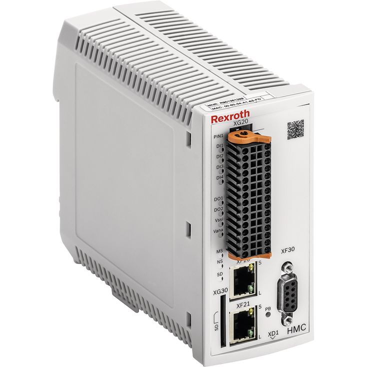
符合IEC 61131-3的PLC功能。
同级领先的液压控制器。
可通过参数切换总线从站连接与TCP/IP维修接口;支持Sercos、EtherNet IP、PROFINET RT、EtherCAT、PROFIBUS及Powerlink。
液压轴测量系统:增量式或绝对式(SSI、Endat2.2),以及±10 V、4至20 mA模拟信号。
按照电磁兼容指令2004/108/EC加贴CE标志。
01 | 02 | 03 | 04 | 05 | 06 | 07 | ||||||||
VT | \u2013 | HMC | \u2013 | \u2013 | 1X | / | M | \u2013 | \u2013 | 00 | / | 00 |
Type | ||
01 | Digital axis control for hydraulic drives | HMC |
Axis controls | ||
02 | 1 axis | 1 |
2 axes | 2 | |
Component series | ||
03 | Component series 10 ... 19 (10 ... 19: unchanged technical data and pin assignment) | 1X |
Interface | ||
04 | Multi-Ethernet | M |
Bus connection | ||
05 | With Profibus | P |
Without Profibus | O | |
Software option | ||
06 | Standard | 00 |
Hardware option | ||
07 | Standard | 00 |
Mating connector for
XD1 (Weidmüller BLZF 3.50/03/180F SN BK BX)
XG20/XG21 (Weidmüller B2CF 3.50/30/180F SN BK BX)
Operating voltage | Nominal voltage | UB | 24 V DC | ||
Lower limit value | UBmin. | 17.5 V DC | |||
Upper limit value | UBmax. | 30 V DC | |||
maximum admissible residual ripple (40 \u2026 400 Hz) | UPP | 5 V (observe the admissible limits) | |||
Total current consumption | Number of axes | 1 | 2 | ||
Running empty | I | 0.2 \u2026 0.3 A | 0.3 \u2026 0.5 A | ||
Max. admissible load 1) | I | 0.9 \u2026 1.1 A | 1.8 \u2026 2.2 A | ||
Power loss (at 24 V) | W | < 8 | < 14 | ||
External fuse | 3.15 A time-lag | ||||
| 1) | External fuse protection required |
Number (current or voltage parameterizable) | 4 | 8 | |||
Resolution 1) | 14 bit | ||||
Voltage inputs (differential inputs) | Measurement range | \u201310 V \u2026 +10 V | |||
Input resistance | RE | 200 kΩ ±10 % | |||
Linearity at 20 °C | U | mV | < 20 | ||
Noise | U | mV | ± 15 | ||
Temperature drift | < 12 mV/10 K | ||||
Current inputs (reference to AGND) | Input current | IE | 4 mA \u2026 20 mA (0 \u2026 20 mA physical) | ||
Input resistance | RE | 100 Ω measuring resistance plus FET plus diode | |||
Linearity at 20 °C | I | μA | < 20 | ||
Temperature drift | < 12 μA/10 K | ||||
| 1) | related to ±12 V (1.465 mV/Bit) or 20.7 mA (1.27 μA/Bit) |
Number | 4 | 8 | ||
Low level | U | \u20133 V \u2026 5 V | ||
High level | U | 11 V ... UB | ||
Current consumption at high level | I | 2 mA ... 15 mA | ||
Reference potential | GND | |||
Number (current or voltage parameterizable) | 2 | 4 | |||
Resolution 1) | 16 bit | ||||
Voltage outputs | Output range | U | \u201310 V \u2026 +10 V (0 \u2026 10 V via software) | ||
Load, min. | RLmin | Ω | 1000 | ||
Linearity and noise at 20 °C | U | μA | < 35 | ||
Temperature drift | < 12 mV/10 K | ||||
Current outputs | Output range | I | 0 \u2026 20 mA (4 mA \u2026 20 mA via software) | ||
Maximum load | R | Ω | 500 | ||
Linearity and noise at 20 °C | I | mV | < 25 | ||
Temperature drift | < 12 μA/10 K | ||||
| 1) | 0.334 mV/LSB LSB = Least Significant Bit |
Number | 4 | 8 | ||
Low level | U | 0 \u2026 3 V | ||
High level | U | 14.5 V \u2026 UB | ||
Current carrying capacity, max. | Imax | 50 mA (short-circuit-proof) | ||
Signal delay time | t | 0.5 ms \u2026 1.2 ms (depending on the set performance) | ||
Reference potential | GND | |||
Voltage supply for encoder (optional) | +5 Venc | U | 5 VDC ±5 % | ||
Vencoder_SSI | U | UB \u2012 3 V (max. load) ... UB (running empty) | |||
Maximum supply current | I | mA | 300 | ||
Incremental transducer with TTL output | Encoder signals | Two impulse series (A and B, electrically shifted by 90°) and a reference signal (Z) or single ended | |||
Signal form | RS485 | ||||
Maximum input frequency | kHz | 250 | 250 | ||
SSI transducer | Coding 1) | Gray | |||
Data width 1) | 18 ... 28 Bit | ||||
Transfer frequency | 80 ... 500 kBit/s | ||||
Line receiver/driver | RS485 | ||||
Endat encoder | 2.2 | ||||
| 1) | Due to the higher control quality, an SSI transducer with clock synchronization should be used |
Bus systems 1) | PROFIBUS DP (max. 12 MBaud acc. to IEC 61158), Sercos III, PROFINET RT, EtherNet/IP, EtherCAT, Powerlink | ||||
Parameterization interface | Ethernet | ||||
Scan time position controller (minimum) | ms | 0.5 | |||
Booting time | < 15 sec (from switch on until the position control system is active) | ||||
Supply for sensors Vencoder_ANA | Power supply | U | UB \u2012 4 V (max. load) ... UB \u2012 2.5 V (running empty) | ||
Maximum supply current | I | mA | 300 | ||
Environmental conditions, other specifications | Type of protection according to EN 60529 | IP 20 | |||
Ambient temperature range | °C | -20 \u2026 +60 | |||
Maximum admissible temperature change | 5 °C/min | ||||
Transport temperature range | °C | -40 \u2026 +70 | |||
Recommended storage temperature with UV protection | °C | +5 \u2026 +40 | |||
Relative air humidity | 10 \u2026 95 % (without condensation) | ||||
Maximum altitude for use | m | 2000 | |||
UV resistance | Housing is only conditionally UV-resistant. In case of long-term exposure, the colors may change. | ||||
Transport shock according to DIN EN 60068-2-27 | 15 g / 11 ms / 3 axes | ||||
Sine test according to DIN EN 60068-2-6 | 10 \u2026 500 Hz / maximum of 2 g / 10 cycles / 3 axes | ||||
Noise test according to DIN EN 60068-2-64 | 20 \u2026 500 Hz / 2.2 g RMS / 6.6 g peak / 30 min. / 3 axes | ||||
Free fall (in original packaging, see 61131-2) | m | 1 | |||
EMC (electro-magnetic compatibility) | \u200bEN 61000-6-2 / EN 61131-2 | EN 61000-4-2 ESD | 4 kV CD / 8 kV AD with BWK B | ||
EN 61000-4-3 HF radiated | 10 V/m (80 \u2026 2700 MHz) with BWK A | ||||
EN 61000-4-4 Burst | 2 kV with BWK B | ||||
EN 61000-4-5 Surge | 0.5 kV / (sym. / unsym.) with BWK B | ||||
EN 61000-4-6 HF conducted | 10 Veff (150 kHz \u2026 80 MHz) with BWK A | ||||
EN 61000-4-8 Magnetic field 50/60 Hz | 100 A/m with BWK A | ||||
\u200bEN 61000-6-3 / EN 61000-6-4 / EN 61131-2 | EN 55016-2-1 Interference voltage | 0.15 \u2026 30 MHz, class A, EN 55022 | |||
EN 55016-2-3 Radio interference field strength | 30 \u2026 1000 MHz, class A, EN 55022 | ||||
Installation position | Vertical. For the breathing of the assembly, the ventilation slots of the top and bottom side must be at least 2 cm away from covers, walls, etc. | ||||
Installation | Top hat rail TH 35-7.5 or TH 35-15 according to EN 60715 | ||||
Housing material | Glass-fiber reinforced polyamide plastic | ||||
Resistance against aggressive media | Contact with conductive dusts is not admissible. Avoid contact with hydraulic fluids. | ||||
Weight | m | kg | 0.6 | ||
Conformity | CE according to the EMC directive, CE according to the RoHS directive | ||||
| 1) | With the EtherCAT (profile CoE) and Powerlink bus systems, support of the second axis is only possible upon request |
Dimensions in mm
| 1) | Plus 15 mm for connecting/disconnecting the plug-in connector |
Status LED | Display status |
Module (MS) | |
Off | No voltage supply |
Green-red, flashing | Initialization |
Green, flashing | Drive ready for operation |
Green | Drive active |
Orange, flashing | Warning |
Red, flashing | Error |
Network status (NS) | |
Off | No voltage supply |
Green | Operation |
SD card (SD) | |
Off | No SD card available |
Green, flashing | SD card not ready for operation |
Green | SD card available and ready for operation |
digital inputs (Di1 ... Di8) 1) | |
Off | Logic input \u201c0\u201d |
Green | Logic input \u201c1\u201d |
digital outputs (Do1 ... Do4, V∡) 2) | |
Off | Logic output \u201c0\u201d |
Orange | Logic output \u201c1\u201d |
Profibus (PB) | |
Off | Bus not active |
Green | Bus in \u201cData_Exchange\u201d status |
| 1) | 1-axis variant Di1 ... Di4 |
| 2) | 1-axis variant Do1 ... Do2 |
Notices:
For a detailed description of the diagnosis LEDs, please refer to the functional description Rexroth HydraulicDrive HDx20.
VT-HMC 产品文档:
数据表 30239(本数据表)
操作说明书 30239-B
CE 符合性声明(可向 Bosch Rexroth 索取)
VT-HMC 的操作(从软件版本 18V12 起):
Rexroth HydraulicDrive 功能说明,适用于 HDx20 起的版本 1)
Rexroth HydraulicDrive 参数说明,适用于 HDx20 起的版本,RE30330-PA
Rexroth HydraulicDrive 诊断说明,适用于 HDx20 起的版本,RE3030-WA
Rexroth HydraulicDrive、Rexroth IndraMotion MLD (2G) 库说明书,适用于 HDx20 起的库版本
MLD 应用说明
液压元件维护与调试的一般说明:数据表 07800 / 07900
调试软件与文档的网址:www.boschrexroth.com/HMC
维护说明:
设备已在工厂测试,并以默认设置供货。
仅可维修完整的设备。修复后的设备以默认设置返还,不会应用用户特定设置。机器的最终用户必须重新传输相应的用户参数。
说明:
供电电压必须持续接通,否则无法进行总线通信。
仅允许在断电状态下插接或拔出连接器。
在对 EMC 特别敏感的环境中,必须采取额外措施,例如根据应用情况进行屏蔽或滤波 2)
接线信息
信号线路与负载线路之间应保持尽可能大的间距。
信号线不得穿过磁场。
如有可能,信号线应不经中间端子直接敷设。
信号线不得与负载线路平行敷设。
连接电缆屏蔽层(参见操作说明书)
对于数字输入和输出,建议的最大电缆长度为 30 m。
传感器,包括增量式、绝对式或模拟式传感器,只能使用屏蔽线路。建议的最大电缆长度为 50 m;同时应遵守传感器制造商的说明。
连接器 XG20/XG21 的信号没有电气隔离。因此,连接外部设备时,必须始终建立电位参考。
其他说明参见 IndraWorks 在线帮助及操作说明书 30239-B。
上、下通风槽不得被相邻设备遮挡,以确保充分冷却。
请遵守操作说明书 30239-B 中的安装信息。
1)相关文档以 IndraWorks 在线帮助形式提供。
2)HMC 用于家庭或小型商业应用时,为满足 EN61000-6-3 的发射要求,需要采取特殊防护措施,例如安装屏蔽外壳及经过相应认可的滤波系统。