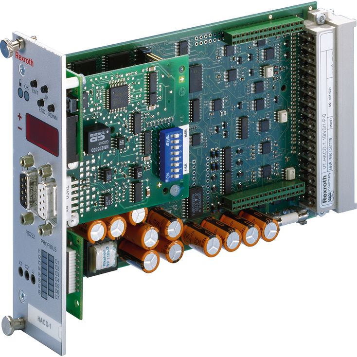
VT-HACD-1-1X/V0/1-0-0 SO026-715
Rexroth
R987212243
可实现切换闭环控制,例如在位置控制上叠加压力/力控制。
用于SSI及增量式数字测量系统的输入。
六个模拟输入,可切换电压(±10 V、0…10 V)及电流(4…20 mA)。
三个模拟输出:AO1可切换为电压(±10 V、0…10 V)或电流(0…20 mA、4…20 mA)输出,AO2和AO3为电压输出(±10 V)。
多种信号关联及切换方式。
使能输入及正常状态输出。
八个数字输入。
七个可配置的数字输出。
可参数化的斜坡功能。
32个程序块,含指令值、速度及控制器参数。
可通过面积匹配、特性曲线修正、死区补偿、残余速度逻辑及零点修正,适配液压驱动装置。
±10 V参考电压输出。
RS232串行接口。
最多32块控制器卡可通过本地总线互联,用于参数设置和诊断。
通过PROFIBUS DP、Motorola格式的PROFIBUS DP、DeviceNet或CANopen与上级控制系统通信。CANopen通过PDO传输数据,因此不提供标准EDS文件。
01 | 02 | 03 | 04 | 05 | 06 | 07 | ||||||
VT-HACD | \u2013 | 1 | \u2013 | 1X | / | V0 | / | 1 | \u2013 | \u2013 |
01 | Digital command value and controller card | VT-HACD |
02 | Standard command value and controller card | 1 |
03 | Component series 10 ... 19 (10 ... 19: unchanged technical data and pin assignment) | 1X |
04 | Basic device | V0 |
05 | With display | 1 |
06 | Without bus connection | O |
PROFIBUS DPV0 | P | |
DeviceNet | D | |
CANopen | C | |
07 | Without valve output stage | 0 |
With valve output stage for 4WRE, component series 2X with two solenoids (only in connection with PROFIBUS) | 1 |
Component series | 1X |
Operating voltage | UB | 24 VDC | ||
Operating voltage | Lower limit value | UB(t)min | V | 21 |
Upper limit value | UB(t)max | V | 30 | |
Current consumption | Imax | Standby current consumption 250 mA | ||
Fuse | IS | 4 A time-lag | ||
Number | 6 | |||
Voltage inputs | Range | U | 0 to 10 V or ±10 V (configurable) | |
Input resistance | Re | 100 kΩ, > 10 MΩ for input AI 1 | ||
Resolution | 5 mV for range ±10 V, 2.5 mV for range 0...10 V | |||
Non-linearity | mV | < 10 | ||
Current inputs | Range | I | 0...20 mA or 4...20 mA | |
Input resistance | Re | 100 Ω | ||
Leakage current | Iv | 0.15 % (with 500 Ω between pin AI x- and 0 V) | ||
Resolution | 5 μA | |||
Signal | log 0 | 0 to 5 V | |
log 1 | 16 V to UB |
Number | 3 | |||
AO1 voltage output | Output voltage | U | 0 to 10 V or ±10 V (configurable) | |
Current, max. | Imax | mA | 10 | |
Load, min. | RLmin | kΩ | 1 | |
Resolution | 1.25 mV (14 bit) | |||
Residual ripple | ±15 mV (without noise) | |||
AO1 current output | Current | I | 0...20 mA or 4...20 mA (configurable) | |
Load, max. | Rmax | Ω | 500 | |
Resolution | 1.25 μ | |||
Residual ripple | ±15 µA (without noise) | |||
AO2/AO3 voltage output | Output voltage | U | ±10 V | |
Current, max. | Imax | mA | 10 | |
Load, min. | RLmin | kΩ | 1 | |
Resolution | 10 mV (11 bit) | |||
Residual ripple | ±25 mV (without noise) | |||
Signal | log 0 | 0 to 5 V | ||
log 1 | 16 V to (UB - 3 V) | |||
Current, max. | Imax | mA | 30 | |
Incremental transducer | Signal level | U | 5...24 V | |
SSI transducer | Line receiver/driver | RS485 |
Reference voltage | U | V | ± 10 | |
Load, max. | Imax | mA | 30 | |
Residual ripple | mV | < 20 | ||
Scanning time | t | ms | 2 | |
Interface, serial | RS 232 (front plate), D-Sub socket | |||
Valve output stage (optional) | Solenoid current per solenoid, max. | Imax | A | 2.5 |
Valve position transducer | Oscillator amplitude | U | V | 13 |
Oscillator frequency | f | kHz | 5.7 | |
Coil resistance at 20°C | R20 | between coil connection 1 and 2: 130 to 164 Ω between coil connection 3 and 4: 21 to 24 Ω | ||
Additional technical data | see data sheet valve 4WRE...2X (29061) | |||
Anschlussart | 64-pin male connector, DIN 41612, form G | |||
Local bus, distance to the furthermost device, max. | I | max. 280 m line length | ||
Operating temperature range | ϑ | °C | \u200b0 \u2026 +50 | |
Storage temperature range | ϑ | °C | -20 \u2026 +70 | |
Weight | m | g | 0.2 | |