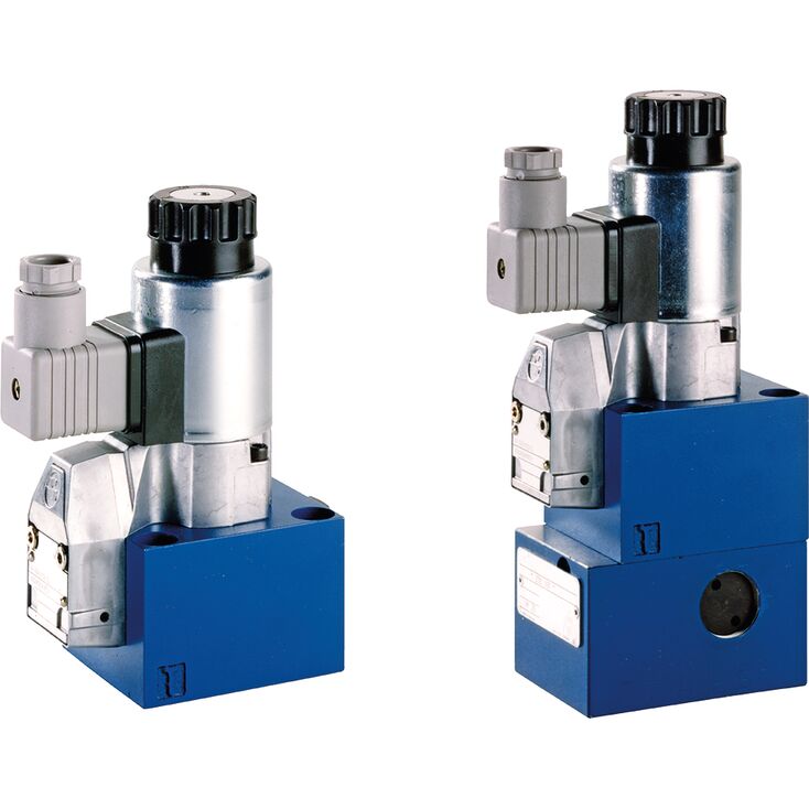
M-3SEW 10 C1X/420MG24N9K4
Rexroth
R900075565
电磁驱动的直动式座阀换向阀。
油口布置符合ISO 4401-05-04-0-05。
封闭油口无泄漏关闭。
即使长时间带压停机后,仍可可靠切换。
气隙式直流电磁铁,线圈可拆卸;通过整流器也可使用交流电源。
电磁线圈可旋转90°。
采用独立电气连接。
可选隐蔽式手动应急操作。
可选感应式位置开关,非接触检测。
概述
M-.SEW型换向阀是电磁驱动的座阀换向阀,用于控制流动的启动、停止及方向。
主要由阀体(1)、电磁铁(2)、淬硬的阀系统(3),以及作为关闭元件的阀芯(8)组成。
基本原理
初始位置时,控制阀芯(8)由弹簧(9)压向阀座;切换后则由电磁铁(2)压向阀座。电磁铁(2)的力经弯角杠杆(6)和钢球(7)传至两侧均密封的阀芯(8)。两个密封件之间的腔体与 P 口连通,因此,阀系统(3)相对于操作力(电磁铁力或复位弹簧力)实现压力平衡。由此,阀可用于最高 630 bar 的压力。
注意!
二位三通座阀式换向阀采用“阀芯负遮盖”。因此,T 口必须始终接通。也就是说,在切换过程中,从一个阀座开始开启至另一个阀座完全关闭,P–A–T 各油口会相互连通。不过,这一过程持续时间很短,在几乎所有应用中都不会产生明显影响。
手动应急操作(10)可在电磁铁未通电时切换阀。
注意!
必须确保不超过所规定的最大流量!必要时,应安装用于限制流量的节流插装件,参见功能说明。
阀座布置提供以下选项:
阀芯机能符号“U”
阀芯机能符号“C”
在二位三通座阀式换向阀下方安装Plus-1叠加板,可实现二位四通座阀式换向阀功能。
Plus-1 叠加板的功能:
初始位置
主阀未动作时,弹簧(9)使球(4)压在阀座(11)上,P口封闭,A与T相通。另有控制管路从A连接至控制阀芯(12)的大端面,使其向油箱卸压。P口压力将球(13)压向阀座(14),因此P与B相通,A与T相通。
过渡位置:
主阀动作时,阀芯(8)克服弹簧(9)移向阀座(15)并压紧。过程中T口封闭,P、A、B短暂互通。
阀芯位置:
P 与 A 连通。泵压经 A 口作用于控制阀芯(12)的大面积上,将钢球(13)压在阀座(16)上,从而使 B 与 T 连通、P 与 A 连通。Plus-1 叠加板中的钢球(13)具有“正遮盖”。
注意!
使用差动缸时,为避免压力放大,必须将油缸的环形面积一侧连接至 A 口。
Plus-1板与阀座布置的组合提供以下选项:
阀芯机能符号“D”
阀芯机能符号“Y”
若运行条件导致切换过程中可能出现超过阀性能极限的流量,则必须使用节流插芯。
示例:
蓄能器运行,
作为内部先导取油的先导控制阀使用。
二位三通座阀式换向阀(见功能说明)
节流插芯装入座阀的P口。
二位四通座阀式换向阀(见功能说明)
节流插芯装入Plus-1板的P口。
单向阀插芯允许油液由P自由流向A,并以无泄漏方式封闭由A至P的流动。
二位三通座阀式换向阀(见功能说明)
单向阀插芯装入座阀的P口。
二位四通座阀式换向阀(见功能说明)
单向阀插芯装入Plus-1板的P口。
01 | Mineral oil | M | |||
02 | 3 main ports | 3 | |||
4 main ports | 4 | ||||
03 | Seat valve | SEW | |||
04 | Size 10 | 10 | |||
05 | Main ports | 3 | 4 | ||
Symbol | | ● | – | U | |
| | ● | – | C | ||
| | – | ● | D | ||
| | – | ● | Y | ||
● = available | |||||
06 | Component series 10 ... 19 (10 ... 19: unchanged installation and connection dimensions) | 1X | |||
07 | Operating pressure 420 bar | 420 bar | |||
Operating pressure 630 bar | 630 bar | ||||
08 | Solenoid (air-gap) with detachable coil | M | |||
09 | Direct voltage 24 V | G24 | |||
Nominal voltage 96 V at DC solenoid in operation with alternating voltage (AC voltage mains 110/120 V - 50/60 Hz with an admissible voltage tolerance of +/- 10 %) | G96 | ||||
Nominal voltage 110 V at DC solenoid with operation with AC voltage mains (AC voltage mains 110 V/120 V – 50/60 Hz with an admissible voltage tolerance of +/-10 %) | G110 | ||||
Nominal voltage 205 V at DC solenoid with operation with AC voltage mains (AC voltage mains 230 V – 50/60 Hz with an admissible voltage tolerance of +/- 10 %) | G205 2) | ||||
10 | With concealed manual override | N9 | |||
Without manual override | no code | ||||
Electrical connection | |||||
11 | Individual connection | ||||
Without mating connector, with connector DIN EN 175301-803 | K41;2) | ||||
With M12x1 plug-in connection, high-performance version 5-pole, integrated interference protection circuit, operating display with LED | K72L3) | ||||
Spool position monitoring | |||||
12 | Without position switch | no code | |||
Monitored spool position "a" | QMAG24 | ||||
Monitored spool position "b" | QMBG24 | ||||
13 | Without check valve insert, without throttle insert | no code | |||
With check valve insert | P | ||||
Throttle Ø 1.2 mm | B12 | ||||
Throttle Ø 1.5 mm | B15 | ||||
Throttle Ø 1.8 mm | B18 | ||||
Throttle Ø 2.0 mm | B20 | ||||
Throttle Ø 2.2 mm | B22 | ||||
Seal material | |||||
14 | NBR seals | no code | |||
FKM seals (other seals upon request) | V | ||||
Observe compatibility of seals with hydraulic fluid used. | |||||
15 | Further details in the plain text | * | |||
01 | 02 | 03 | 04 | 05 | 06 | 07 | 08 | 09 | 10 | 11 | 12 | 13 | 14 | |||
M | – | SEW | 10 | 1X | / | M | K4 | / |
Preferred types and standard units are contained in the EPS (standard price list).
Size | 10 | ||
Weight | Valve with one actuation cylinder | kg | 3.6 |
Valve with two actuation cylinders | kg | 3.6 | |
Operating force | with detent "F" | N | 30 … 40 |
With spring return | N | 18 … 20 | |
Installation position | any | ||
Ambient temperature range | NBR seals | °C | -20 … +70 |
FKM seals | °C | -15 … +70 | |
Storage temperature range | °C | -20 … +50 | |
Size | 10 | ||
Maximum operating pressure | Port P | bar | 350 |
Port A | bar | 350 | |
Port B | bar | 350 | |
Port T 1) | bar | 210 | |
Maximum flow | l/min | 160 | |
Hydraulic fluid | see table | ||
Hydraulic fluid temperature range 2) | NBR seals | °C | -20 … +80 |
FKM seals | °C | -15 … +80 | |
Viscosity range | mm²/s | 2.8 … 500 | |
Maximum admissible degree of contamination of the hydraulic fluid 3) | Class 20/18/15 according to ISO 4406 (c) | ||
| 1) | With symbols A or B, port T must be used as leakage oil connection if the operating pressure exceeds the admissible tank pressure. |
| 2) | at the valve working ports of the valve |
| 3) | The cleanliness classes specified for the components must be adhered to in hydraulic systems. Effective filtration prevents faults and simultaneously increases the life cycle of the components. For the selection of the filters, see www.boschrexroth.com/filter. |
Hydraulic fluid | Classification | Suitable sealing materials | Standards | |
Mineral oils and related hydrocarbons | HL, HLP, HLPD, HVLP, HVLPD | NBR, FKM | DIN 51524 | |
Bio-degradable | Insoluble in water | HETG | NBR, FKM | VDMA 24568 |
HEES | FKM | |||
Soluble in water | HEPG | FKM | VDMA 24568 | |
Containing water | Water-free | HFDU, HFDR | FKM | ISO 12922 |
Containing water | HFC (Fuchs Hydrotherm 46M, Petrofer Ultra Safe 620) |
NBR
| ISO 12922 | |
Important information on hydraulic fluids!
Flame-resistant – containing water:
| ||||