| Availability: | |
|---|---|
| Quantity: | |

M-3SEW 10 C1X/420MG24N9K4
Rexroth
R900075565
Direct operated directional seat valve with solenoid actuation
Porting pattern according to ISO 4401-05-04-0-05
Blocked port is leak-free closed
Reliable switching when under pressure over longer periods of standstill
Air-gap DC solenoids with detachable coil (AC voltage possible by means of a rectifier)
Solenoid coil is rotatable by 90°
Electrical connection as individual connection
With concealed manual override, optional
Inductive position switch (contactless), optional
General
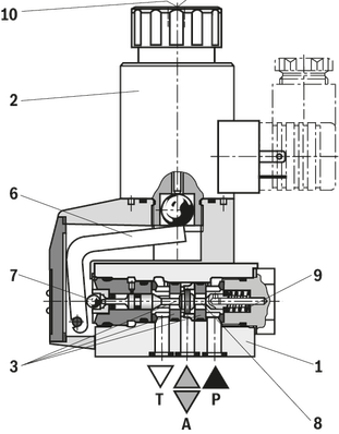
The directional valve of the M-.SEW type is a directional seat valve with solenoid actuation. It controls the start, stop and direction of flow.
It basically comprises a housing (1), the solenoid (2), the hardened valve system (3) and the spool (8) as closing element.
Basic principle
In the initial position, the control spool (8) is pressed onto the seat by the spring (9) and in spool position by the solenoid (2). The force of the solenoid (2) acts via the angled lever (6) and the ball (7) on the spool (8) that is sealed on two sides. The chamber between the two sealing elements is connected to port P. Therefore, the valve system (3) is pressure-compensated in relation to the actuating forces (solenoid or return spring). Therefore, the valves can be used up to 630 bar.
Notice!
3/2-directional seat valves feature "negative spool overlap". Therefore, port T must always be connected. That means that during the switching process – from the starting of the opening of one valve seat to the closing of the other valve seat – ports P–A–T are connected with each other. However, this process takes place within such a period of time that it is irrelevant in nearly all cases of use.
The manual override (10) allows for the switching of the valve without solenoid energization.
Attention!
It is to be ensured that the maximum flow indicated is not exceeded! If applicable, a throttle insert for flow limitation is to be inserted (see functional description).
The seat arrangement offers the following options:
Control spool symbol “U“

Control spool symbol “C”

With a sandwich plate, the Plus-1 plate, under the 3/2 directional seat valve, the function of a 4/2 directional seat valve is achieved.
Function of the Plus-1 plate:
Initial position
The main valve is not operated. The spring (9) holds the ball (4) on the seat (11). Port P is blocked and A is connected to T. Apart from that, one control line is connected from A to the large area of the control spool (12), which is thus unloaded to the tank. The pressure applied via P now pushes the ball (13) onto the seat (14). Now, P is connected to B, and A to T.
Transition position:
When the main valve is actuated, the spool (8) is shifted against the spring (9) and pressed onto the seat (15). During this, port T is blocked, while P, A, and B are briefly connected to each other.
Spool position:
P is connected to A. As the pump pressure acts via A on the large area of the control spool (12), the ball (13) is pressed onto the seat (16). Thus, B is connected to T, and P to A. The ball (13) in the Plus-1 plate has a "positive spool overlap".
Attention!
In order to avoid pressure intensification when using differential cylinders, the annulus area of the cylinder must be connected at A.
The use of the Plus-1 plate and the seat arrangement offer the following options:
Control spool symbol “D”

Control spool symbol “Y”


The use of a throttle insert is required if, due to prevailing operating conditions, flows which exceed the performance limit of the valve can occur during the switching processes.
Examples:
Accumulator operation,
use as pilot control valve with internal pilot fluid tapping.
3/2 directional seat valve (see functional description)
The throttle insert is inserted into port P of the seat valve.
4/2 directional seat valve (see functional description)
The throttle insert is inserted into port P of the Plus-1 plate.
The check valve insert allows a free flow from P to A and closes A to P in a leak-free form.
3/2 directional seat valve (see functional description)
The check valve insert is inserted into port P of the seat valve.
4/2 directional seat valve (see functional description)
The check valve insert is inserted into port P of the Plus-1 plate.
General
The directional valve of the M-.SEW type is a directional seat valve with solenoid actuation. It controls the start, stop and direction of flow.
It basically comprises a housing (1), the solenoid (2), the hardened valve system (3) and the spool (8) as closing element.
Basic principle
In the initial position, the control spool (8) is pressed onto the seat by the spring (9) and in spool position by the solenoid (2). The force of the solenoid (2) acts via the angled lever (6) and the ball (7) on the spool (8) that is sealed on two sides. The chamber between the two sealing elements is connected to port P. Therefore, the valve system (3) is pressure-compensated in relation to the actuating forces (solenoid or return spring). Therefore, the valves can be used up to 630 bar.
Notice!
3/2-directional seat valves feature "negative spool overlap". Therefore, port T must always be connected. That means that during the switching process – from the starting of the opening of one valve seat to the closing of the other valve seat – ports P–A–T are connected with each other. However, this process takes place within such a period of time that it is irrelevant in nearly all cases of use.
The manual override (10) allows for the switching of the valve without solenoid energization.
Attention!
It is to be ensured that the maximum flow indicated is not exceeded! If applicable, a throttle insert for flow limitation is to be inserted (see functional description).
The seat arrangement offers the following options:
Control spool symbol “U“
Control spool symbol “C”
With a sandwich plate, the Plus-1 plate, under the 3/2 directional seat valve, the function of a 4/2 directional seat valve is achieved.
Function of the Plus-1 plate:
Initial position
The main valve is not operated. The spring (9) holds the ball (4) on the seat (11). Port P is blocked and A is connected to T. Apart from that, one control line is connected from A to the large area of the control spool (12), which is thus unloaded to the tank. The pressure applied via P now pushes the ball (13) onto the seat (14). Now, P is connected to B, and A to T.
Transition position:
When the main valve is actuated, the spool (8) is shifted against the spring (9) and pressed onto the seat (15). During this, port T is blocked, while P, A, and B are briefly connected to each other.
Spool position:
P is connected to A. As the pump pressure acts via A on the large area of the control spool (12), the ball (13) is pressed onto the seat (16). Thus, B is connected to T, and P to A. The ball (13) in the Plus-1 plate has a "positive spool overlap".
Attention!
In order to avoid pressure intensification when using differential cylinders, the annulus area of the cylinder must be connected at A.
The use of the Plus-1 plate and the seat arrangement offer the following options:
Control spool symbol “D”
Control spool symbol “Y”
The use of a throttle insert is required if, due to prevailing operating conditions, flows which exceed the performance limit of the valve can occur during the switching processes.
Examples:
Accumulator operation,
use as pilot control valve with internal pilot fluid tapping.
3/2 directional seat valve (see functional description)
The throttle insert is inserted into port P of the seat valve.
4/2 directional seat valve (see functional description)
The throttle insert is inserted into port P of the Plus-1 plate.
The check valve insert allows a free flow from P to A and closes A to P in a leak-free form.
3/2 directional seat valve (see functional description)
The check valve insert is inserted into port P of the seat valve.
4/2 directional seat valve (see functional description)
The check valve insert is inserted into port P of the Plus-1 plate.
01 | Mineral oil | M | |||
02 | 3 main ports | 3 | |||
4 main ports | 4 | ||||
03 | Seat valve | SEW | |||
04 | Size 10 | 10 | |||
05 | Main ports | 3 | 4 | ||
Symbol | | ● | – | U | |
| | ● | – | C | ||
| | – | ● | D | ||
| | – | ● | Y | ||
● = available | |||||
06 | Component series 10 ... 19 (10 ... 19: unchanged installation and connection dimensions) | 1X | |||
07 | Operating pressure 420 bar | 420 bar | |||
Operating pressure 630 bar | 630 bar | ||||
08 | Solenoid (air-gap) with detachable coil | M | |||
09 | Direct voltage 24 V | G24 | |||
Nominal voltage 96 V at DC solenoid in operation with alternating voltage (AC voltage mains 110/120 V - 50/60 Hz with an admissible voltage tolerance of +/- 10 %) | G96 | ||||
Nominal voltage 110 V at DC solenoid with operation with AC voltage mains (AC voltage mains 110 V/120 V – 50/60 Hz with an admissible voltage tolerance of +/-10 %) | G110 | ||||
Nominal voltage 205 V at DC solenoid with operation with AC voltage mains (AC voltage mains 230 V – 50/60 Hz with an admissible voltage tolerance of +/- 10 %) | G205 2) | ||||
10 | With concealed manual override | N9 | |||
Without manual override | no code | ||||
Electrical connection | |||||
11 | Individual connection | ||||
Without mating connector, with connector DIN EN 175301-803 | K41;2) | ||||
With M12x1 plug-in connection, high-performance version 5-pole, integrated interference protection circuit, operating display with LED | K72L3) | ||||
Spool position monitoring | |||||
12 | Without position switch | no code | |||
Monitored spool position "a" | QMAG24 | ||||
Monitored spool position "b" | QMBG24 | ||||
13 | Without check valve insert, without throttle insert | no code | |||
With check valve insert | P | ||||
Throttle Ø 1.2 mm | B12 | ||||
Throttle Ø 1.5 mm | B15 | ||||
Throttle Ø 1.8 mm | B18 | ||||
Throttle Ø 2.0 mm | B20 | ||||
Throttle Ø 2.2 mm | B22 | ||||
Seal material | |||||
14 | NBR seals | no code | |||
FKM seals (other seals upon request) | V | ||||
Observe compatibility of seals with hydraulic fluid used. | |||||
15 | Further details in the plain text | * | |||
01 | 02 | 03 | 04 | 05 | 06 | 07 | 08 | 09 | 10 | 11 | 12 | 13 | 14 | |||
M | – | SEW | 10 | 1X | / | M | K4 | / |
Preferred types and standard units are contained in the EPS (standard price list).
Size | 10 | ||
Weight | Valve with one actuation cylinder | kg | 3.6 |
Valve with two actuation cylinders | kg | 3.6 | |
Operating force | with detent "F" | N | 30 … 40 |
With spring return | N | 18 … 20 | |
Installation position | any | ||
Ambient temperature range | NBR seals | °C | -20 … +70 |
FKM seals | °C | -15 … +70 | |
Storage temperature range | °C | -20 … +50 | |
Size | 10 | ||
Maximum operating pressure | Port P | bar | 350 |
Port A | bar | 350 | |
Port B | bar | 350 | |
Port T 1) | bar | 210 | |
Maximum flow | l/min | 160 | |
Hydraulic fluid | see table | ||
Hydraulic fluid temperature range 2) | NBR seals | °C | -20 … +80 |
FKM seals | °C | -15 … +80 | |
Viscosity range | mm²/s | 2.8 … 500 | |
Maximum admissible degree of contamination of the hydraulic fluid 3) | Class 20/18/15 according to ISO 4406 (c) | ||
| 1) | With symbols A or B, port T must be used as leakage oil connection if the operating pressure exceeds the admissible tank pressure. |
| 2) | at the valve working ports of the valve |
| 3) | The cleanliness classes specified for the components must be adhered to in hydraulic systems. Effective filtration prevents faults and simultaneously increases the life cycle of the components. For the selection of the filters, see www.boschrexroth.com/filter. |
Hydraulic fluid | Classification | Suitable sealing materials | Standards | |
Mineral oils and related hydrocarbons | HL, HLP, HLPD, HVLP, HVLPD | NBR, FKM | DIN 51524 | |
Bio-degradable | Insoluble in water | HETG | NBR, FKM | VDMA 24568 |
HEES | FKM | |||
Soluble in water | HEPG | FKM | VDMA 24568 | |
Containing water | Water-free | HFDU, HFDR | FKM | ISO 12922 |
Containing water | HFC (Fuchs Hydrotherm 46M, Petrofer Ultra Safe 620) |
NBR
| ISO 12922 | |
Important information on hydraulic fluids!
Flame-resistant – containing water:
| ||||
Size | 10 | ||
Weight | Valve with one actuation cylinder | kg | 3.6 |
Valve with two actuation cylinders | kg | 3.6 | |
Operating force | with detent "F" | N | 30 … 40 |
With spring return | N | 18 … 20 | |
Installation position | any | ||
Ambient temperature range | NBR seals | °C | -20 … +70 |
FKM seals | °C | -15 … +70 | |
Storage temperature range | °C | -20 … +50 | |
Size | 10 | ||
Maximum operating pressure | Port P | bar | 350 |
Port A | bar | 350 | |
Port B | bar | 350 | |
Port T 1) | bar | 210 | |
Maximum flow | l/min | 160 | |
Hydraulic fluid | see table | ||
Hydraulic fluid temperature range 2) | NBR seals | °C | -20 … +80 |
FKM seals | °C | -15 … +80 | |
Viscosity range | mm²/s | 2.8 … 500 | |
Maximum admissible degree of contamination of the hydraulic fluid 3) | Class 20/18/15 according to ISO 4406 (c) | ||
| 1) | With symbols A or B, port T must be used as leakage oil connection if the operating pressure exceeds the admissible tank pressure. |
| 2) | at the valve working ports of the valve |
| 3) | The cleanliness classes specified for the components must be adhered to in hydraulic systems. Effective filtration prevents faults and simultaneously increases the life cycle of the components. For the selection of the filters, see www.boschrexroth.com/filter. |
Hydraulic fluid | Classification | Suitable sealing materials | Standards | |
Mineral oils and related hydrocarbons | HL, HLP, HLPD, HVLP, HVLPD | NBR, FKM | DIN 51524 | |
Bio-degradable | Insoluble in water | HETG | NBR, FKM | VDMA 24568 |
HEES | FKM | |||
Soluble in water | HEPG | FKM | VDMA 24568 | |
Containing water | Water-free | HFDU, HFDR | FKM | ISO 12922 |
Containing water | HFC (Fuchs Hydrotherm 46M, Petrofer Ultra Safe 620) |
NBR
| ISO 12922 | |
Important information on hydraulic fluids!
Flame-resistant – containing water:
| ||||


