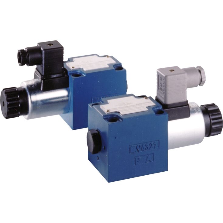
M-3SED 10 UK1X/350CG24N9K4
Rexroth
R900051053
电磁驱动的直动式座阀换向阀。
底板需单独订购。
封闭的连接口具有无泄漏密封性。
即使长时间带压停机后,仍可可靠切换。
湿式直流电磁铁,线圈可拆卸;通过整流器也可使用交流电源。
电磁线圈可旋转90°。
更换线圈无需打开耐压密封腔。
采用独立电气连接。
可选隐蔽式手动应急操作。
感应式位置开关及接近传感器,非接触检测。
二位三通座阀式换向阀
概述
M-.SED型换向阀是电磁驱动的直动式座阀换向阀,用于控制流动的启动、停止及方向,主要由阀体(1)、电磁铁(2)、阀座(7)、(11)以及关闭元件(4)组成。
手动应急操作(6)可在电磁铁未通电时切换阀。
基本原理
阀的初始状态为常开UK或常闭CK,由弹簧(5)的布置决定。关闭元件(4)后方的腔室(3)与P口相连,并与另一油口密封隔离;
T。因此,阀相对于操作力(电磁铁力和弹簧力)实现压力平衡。
采用特殊关闭元件(4),P、A、T口均可承受350 bar最高工作压力,油液也可双向流动,参见符号!
初始位置时,关闭元件(4)由弹簧(5)压在阀座(11)上;切换后,则由电磁铁(2)压在阀座(7)上,流路无泄漏地截止。
在二位三通座阀式换向阀下方安装Plus-1叠加板,可实现二位四通座阀式换向阀功能。
Plus-1 叠加板的功能
初始位置:
主阀未动作时,弹簧(5)使关闭元件(4)压在阀座(11)上,P口封闭,A与T相通。另有控制管路从A连接至控制阀芯(8)的大端面,使其向油箱卸压。P口压力将球(9)压向阀座(10),因此P与B相通,A与T相通。
过渡位置:
主阀动作时,关闭元件(4)克服弹簧(5)移向阀座(7)并压紧。过程中T口封闭,而P、A、B会短暂互通。
切换位置:
P 与 A 连通。泵压经 A 口作用于控制阀芯(8)的大面积上,将钢球(9)压在阀座(12)上,从而使 B 与 T 连通、P 与 A 连通。Plus-1 叠加板中的钢球(9)具有“正遮盖”。
“UK”版本。
“CK”版本。
二位四通座阀式换向阀
概述
M-.SED型换向阀是电磁驱动的直动式座阀换向阀,用于控制流动的启动、停止及方向,主要由阀体(1)、电磁铁(2)、阀座(7)、(11)以及关闭元件(4)组成。
手动应急操作(6)可在电磁铁未通电时切换阀。
基本原理
阀的初始状态为常开UK或常闭CK,由弹簧(5)的布置决定。关闭元件(4)后方的腔室(3)与P口相连,并与另一油口密封隔离;
T。因此,阀相对于操作力(电磁铁力和弹簧力)实现压力平衡。
采用特殊关闭元件(4),P、A、T口均可承受350 bar最高工作压力,油液也可双向流动,参见符号!
初始位置时,关闭元件(4)由弹簧(5)压在阀座(11)上;切换后,则由电磁铁(2)压在阀座(7)上,流路无泄漏地截止。
在二位三通座阀式换向阀下方安装Plus-1叠加板,可实现二位四通座阀式换向阀功能。
Plus-1 叠加板的功能
初始位置:
主阀未动作时,弹簧(5)使关闭元件(4)压在阀座(11)上,P口封闭,A与T相通。另有控制管路从A连接至控制阀芯(8)的大端面,使其向油箱卸压。P口压力将球(9)压向阀座(10),因此P与B相通,A与T相通。
过渡位置:
主阀动作时,关闭元件(4)克服弹簧(5)移向阀座(7)并压紧。过程中T口封闭,而P、A、B会短暂互通。
切换位置:
P 与 A 连通。泵压经 A 口作用于控制阀芯(8)的大面积上,将钢球(9)压在阀座(12)上,从而使 B 与 T 连通、P 与 A 连通。Plus-1 叠加板中的钢球(9)具有“正遮盖”。
注意!
使用差动缸时,为避免压力放大,必须将油缸的环形面积一侧连接至 A 口。
Plus-1板与阀座布置的组合提供以下选项:
“D”版本。
“Y”版本。
M-4SED 10 Y 1X/350CG24N9K4型。
若运行条件导致切换过程中可能出现超过阀性能极限的流量,则必须使用节流插芯。
示例:
蓄能器运行,
作为内部先导取油的先导控制阀使用。
二位三通座阀式换向阀
节流插芯装入座阀的P口。
二位四通座阀式换向阀
节流插芯装入Plus-1板的P口。
单向阀插芯允许油液由P自由流向A,并以无泄漏方式封闭由A至P的流动。
二位三通座阀式换向阀
单向阀插芯装入座阀的P口。
二位四通座阀式换向阀
单向阀插芯装入Plus-1板的P口。
01 | 02 | 03 | 04 | 05 | 06 | 07 | 08 | 09 | 10 | 11 | 12 | 13 | 14 | 15 | 16 | 17 | 18 | 19 | 20 | 21 | 22 | |
DB | 5X | / | * |
01 | Pressure relief valve | DB |
02 | Without directional valve | no code |
03 | Pilot-operated valve (complete) | no code |
Pilot control valve without main spool insert (do not enter any size) | C | |
Pilot control valve with main spool insert (enter size 10 or 30) | C | |
Pilot control valve without main spool insert for subplate mounting (do not enter any size) | T 1) | |
04 | Size 10 | |
Subplate mounting "no code" | 10 | |
Threaded connection "G" | 10 (G1/2) | |
Size 16 | ||
Threaded connection "G" | 15 (G3/4) | |
Size 25 | ||
Subplate mounting "no code" | 20 | |
Threaded connection "G" | 20 (G1) | |
Threaded connection "G" | 25 (G1 1/4) | |
Size 32 | ||
Subplate mounting "no code" | 30 | |
Threaded connection "G" | 30 (G1 1/2) | |
05 | Without directional valve | no code |
Type of connection | ||
06 | Subplate mounting or cartridge valve | no code |
For threaded connection | G | |
Adjustment type for pressure adjustment | ||
07 | Rotary knob (not for version "C" and "T") | 1 |
Sleeve with hexagon and protective cap | 2 | |
Lockable rotary knob with scale | 3 2) | |
Rotary knob with scale | 7 | |
08 | Main spool Ø24 mm (all sizes) | – |
Main spool Ø28 mm (only for NG32) | N | |
09 | Component series 50 … 59 (50 … 59: unchanged installation and connection dimensions) | 5X |
10 | Set pressure up to 50 bar | 50 |
Set pressure up to 100 bar | 100 | |
Set pressure up to 200 bar | 200 | |
Set pressure up to 315 bar | 315 | |
Set pressure up to 350 bar | 350 | |
Pilot oil flow | ||
11 | External pilot oil supply, internal pilot oil return | X 3) |
Internal pilot oil supply, external pilot oil return | Y | |
Pilot oil supply and pilot oil return external | XY 3) | |
12 | Standard version | no code |
Valve for minimum cracking pressure (not for versions "without main spool insert" and not suitable for mutual relief) | U 4) | |
13 | Without switching shock damping | no code |
14 | Without directional valve | no code |
15 | Without directional valve | no code |
16 | Without manual override | no code |
Electrical connection | ||
17 | Without directional valve | no code |
18 | Without directional valve | no code |
Corrosion resistance | ||
19 | None | no code |
Improved corrosion protection (240 h salt spray test according to EN ISO 9227) | J3 5) | |
Seal material | ||
20 | NBR seals | no code |
FKM seals | V | |
Observe compatibility of seals with hydraulic fluid used. (Other seals upon request) | ||
Equipment Directive | ||
21 | Without type-examination procedure | no code |
Type-examination tested safety valve according to Pressure Equipment Directive 2014/68/EU | E | |
22 | Further details in the plain text | * |
| 1) | DBT corresponds to DBC, however with closed central bore |
| 2) | H-Key with material no. R900008158 is included in the scope of delivery. |
| 3) | Not with version "DBC" |
| 4) | Only possible up to pressure rating 315 bar |
| 5) | Only version "2", however without protective cap |
(Component series 5X according to Pressure Equipment Directive 2014/68/EU)
NG | Type designation | Component marking | Maximum flow qVmaxin l/min with pilot oil return | Set response overpressure p in bar | |
external "Y" | internal "–" | ||||
10 | | TÜV.SV.▢ – 851.12.F.G.p | 170 230 230 230 | 130 200 200 200 | 30 ... 60 61 ... 110 111 ... 210 211 ... 350 |
25 | | TÜV.SV.▢ – 852.22.F.G.p | 250 270 420 450 | 180 210 320 400 | 30 ... 60 61 ... 110 111 ... 210 211 ... 350 |
32 | | TÜV.SV.▢ – 853.32.F.G.p | 600 600 650 700 | 225 340 540 580 | 30 ... 60 61 ... 110 111 ... 210 211 ... 350 |
1 | For subplate mounting | no code |
For threaded connection | G | |
Adjustment type for pressure adjustment | ||
2 | Hand wheel (pressure adjustment sealed, unloading or setting of a lower response pressure possible!) | 1 |
With sealed protective cap (no adjustment/unloading possible) | 2 | |
Pressure | ||
3 | To be entered by the customer, e.g. pressure adjustment ≥ 30 bar and possible in 5 bar steps. | e.g. 150 |
Pilot oil flow | ||
4 | Pilot oil supply internal, pilot oil return internal | no code |
Pilot oil supply internal, pilot oil return external (Recommendation) | Y 1) | |
5 | NBR seals | no code |
FKM seals | V | |
▢ | Value entered at the factory | |
| 1) | Pilot oil supply external "X" not possible |
Size | 10 | ||
Weight | 3/2 directional seat valve | kg | 2.6 |
4/2 directional seat valve | kg | 3.9 | |
Installation position | any | ||
Ambient temperature range | NBR seals | °C | -30 … +50 |
FKM seals | °C | -20 … +50 | |
Hydraulic fluid | Classification | Suitable sealing materials | Standards | |
Mineral oil | HL, HLP | FKM, NBR | DIN 51524 | |
Bio-degradable | Insoluble in water | HEES (synthetic esters) | FKM | VDMA 24568 |
HETG (rape seed oil) | FKM, NBR | |||
Soluble in water | HEPG (polyglycols) | FKM | VDMA 24568 | |
Other hydraulic fluids on request | ||||
电气
Voltage type | Direct voltage | AC voltage | ||
Available voltages | V | 12 / 24 / 42 / 96 / 110 / 205 / 220 1) | 110 / 120 / 230 | |
Voltage tolerance (nominal voltage) | % | ± 10 | ||
Power consumption | W | 30 | ||
Duty cycle | % | 100 | ||
Switching time according to ISO 6403 | ON | ms | 20 … 50 | |
OFF (without rectifier) | ms | 5 … 25 | ||
OFF (with rectifier) | ms | 30 … 50 | ||
Maximum switching frequency | 1/h | 15000 | ||
Protection class according to EN 60529 | IP65 (If a suitable and a correctly mounted mating connector are used.) | |||
Maximum coil temperature | °C | 150 | ||
| 1) | Other voltages upon request |
电气连接时,应按规定连接保护接地导线(PE,接地)。
电气连接通过带 M12 x 1 连接螺纹的 4 极配套连接器实现,连接器需单独订购。
Connection voltage (DC voltage) | V | 24 | ||
Voltage tolerance (connection voltage) | +30 %/-15 % | |||
Admissible residual ripple | % | ≤ 10 | ||
Max. load capacity | mA | 400 | ||
Switching outputs | PNP transistor outputs, load between switching outputs and GND | |||
Pinout | 1 | V | 24 | |
2, 4 | Switching output | mA | 400 | |
3 | Earthing (GND) | V | 0 | |
M12x1 plug-in connections 1) | K72L | ||
Available voltages 2) | V | 24 | |
Limited switch-off voltage peak | V | -44 … -55 | |
Voltage tolerance (nominal voltage) | % | ± 10 | |
Power consumption | W | 30 | |
Duty cycle | % | 100 | |
Switching time according to ISO 6403 | ON | ms | 30 … 50 |
OFF (without rectifier) | ms | 10 … 20 | |
OFF (with rectifier) | ms | 35 … 45 | |
Maximum switching frequency | Standard | 1/h | 15000 |
Protection class according to EN 60529 3) | IP65 | ||
Protection class according to DIN EN 61140 | III | ||
Maximum coil temperature 4) | °C | 150 | |
| 1) | Mating connectors according to IEC 60947-5-2, separate order, see data sheet 08006 |
| 2) | Connection to functional low voltage with secure separation only = PELV/SELV |
| 3) | Only with the use of the mating connectors indicated by us and with correct installation. |
| 4) | Due to the surface temperatures of the solenoid coils, the standards ISO 13732-1 and EN 982 need to be adhered to! |
Size | 10 | ||
Maximum operating pressure | Port P | bar | 350 |
Port A | bar | 350 | |
Port B | bar | 350 | |
Maximum flow | l/min | 40 | |
Hydraulic fluid | see table | ||
Hydraulic fluid temperature range | NBR seals | °C | -30 … +80 |
FKM seals | °C | -20 … +80 | |
Viscosity range | mm²/s | 2.8 … 500 | |
Maximum admissible degree of contamination of the hydraulic fluid, cleanliness class according to ISO 4406 (c) 1) | Class 20/18/15 according to ISO 4406 (c) | ||
| 1) | The cleanliness classes specified for the components must be adhered to in hydraulic systems. Effective filtration prevents faults and simultaneously increases the life cycle of the components. For the selection of the filters, see www.boschrexroth.com/filter. |
Dimensions in mm
Dimensions in mm
1.2 | Solenoid "b" |
2.1 | Dimension for solenoid with concealed manual override “N9” |
2.2 | Dimension for solenoid without manual override |
3 | Mating connector without circuitry (separate order) |
4 | Mating connector with circuitry (separate order) |
5 | Space required to remove the coil |
6 | Name plate |
7 | Attention! With 3/2 directional seat valves, ports B and TB are available as blind counterbores. With 4/2 directional seat valves, port TB is available as blind counterbore. |
8 | Identical seal rings for ports A, B, and T; seal ring for port P |
10 | Space required to remove the coil |
11 | |
12 | Valve mounting bores |
1.1 | Solenoid “a” |
2.1 | Dimension for solenoid with concealed manual override “N9” |
2.2 | Dimension for solenoid without manual override |
3 | Mating connector without circuitry (separate order) |
4 | Mating connector with circuitry (separate order) |
5 | Space required to remove the coil |
6 | Name plate |
7 | Attention! With 3/2 directional seat valves, ports B and TB are available as blind counterbores. With 4/2 directional seat valves, port TB is available as blind counterbore. |
8 | Identical seal rings for ports A, B, and T; seal ring for port P |
10 | Space required to remove the coil |
11 | |
12 | Valve mounting bores |
4 hexagon socket head cap screws
ISO 4762 - M6 x 40 - 10.9-flZn-240h-L
friction coefficient μtotal = 0.09 to 0.14,
tightening torque MA = 12.5 Nm ± 10%,
material no. R913000058
Subplates (separate order)
G 66/01 (G3/8)
G 67/01 (G1/2)
Dimensions in mm
Dimensions in mm
| 1) | Only version "T" |
1.2 | Solenoid "b" |
2.1 | Dimension for solenoid with concealed manual override “N9” |
2.2 | Dimension for solenoid without manual override |
3 | Mating connector without circuitry (separate order) |
4 | Mating connector with circuitry (separate order) |
5 | Space required to remove the coil |
6 | Name plate |
7 | Attention! With 3/2 directional seat valves, ports B and TB are available as blind counterbores. With 4/2 directional seat valves, port TB is available as blind counterbore. |
8 | Identical seal rings for ports A, B, and T; seal ring for port P |
10 | Space required to remove the coil |
11 | |
12 | Valve mounting bores |
1.1 | Solenoid “a” |
2.1 | Dimension for solenoid with concealed manual override “N9” |
2.2 | Dimension for solenoid without manual override |
3 | Mating connector without circuitry (separate order) |
4 | Mating connector with circuitry (separate order) |
5 | Space required to remove the coil |
6 | Name plate |
7 | Attention! With 3/2 directional seat valves, ports B and TB are available as blind counterbores. With 4/2 directional seat valves, port TB is available as blind counterbore. |
8 | Identical seal rings for ports A, B, and T; seal ring for port P |
10 | Space required to remove the coil |
11 | |
12 | Valve mounting bores |
Dimensions in mm
Dimensions in mm
1.1 | Solenoid “a” |
2.1 | Dimension for solenoid with concealed manual override “N9” |
2.2 | Dimension for solenoid without manual override |
3 | Mating connector without circuitry (separate order) |
4 | Mating connector with circuitry (separate order) |
5 | Space required to remove the coil |
6 | Name plate |
7 | Attention! With 3/2 directional seat valves, ports B and TB are available as blind counterbores. With 4/2 directional seat valves, port TB is available as blind counterbore. |
8 | Identical seal rings for ports A, B, and T; seal ring for port P |
9 | Plus-1 plate |
10 | Space required to remove the coil |
11 | |
13 | Valve mounting screws see dimensions |
4 hexagon socket head cap screws
ISO 4762 - M6 x 40 - 10.9-flZn-240h-L
friction coefficient μtotal = 0.09 to 0.14,
tightening torque MA = 12.5 Nm ± 10%,
material no. R913000059
Dimensions in mm
Dimensions in mm
1.2 | Solenoid "b" |
2.1 | Dimension for solenoid with concealed manual override “N9” |
2.2 | Dimension for solenoid without manual override |
3 | Mating connector without circuitry (separate order) |
4 | Mating connector with circuitry (separate order) |
5 | Space required to remove the coil |
6 | Name plate |
7 | Attention! With 3/2 directional seat valves, ports B and TB are available as blind counterbores. With 4/2 directional seat valves, port TB is available as blind counterbore. |
8 | Identical seal rings for ports A, B, and T; seal ring for port P |
9 | Plus-1 plate |
10 | Space required to remove the coil |
11 | |
13 | Valve mounting screws see dimensions |
Dimensions in mm
| 1) | only NG150 |
Dimensions in mm
| 1) | For dimensions, see valve dimensions |
The dimensions are nominal dimensions which are subject to tolerances.
Dimensions in mm
Dimensions in mm