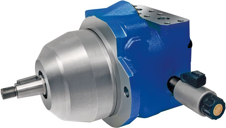
A A10VER 28 EZ7 /52R-VYF10N002P -S5454
Rexroth
R902571309
专为静液压风扇驱动开发。
A10VER变量马达采用可越过中位的旋转组件,最大排量范围为±100% Vg max。无需昂贵的附加部件即可实现反转,以反向气流清除冷却器污物;冷却性能改善有助于节省燃油。
省去外置换向阀,可提高液压风扇驱动的能效。
坚固的轴承,有助于延长使用寿命。
允许的最高输出转速高。
功率重量比优良,尺寸紧凑。
噪声低。
斜盘式结构。
Size | 18 | 23 | 28 | 37 | 45 | |||
Displacement | +100 % Vg max | cm³ | 18 | 23 | 28 | 37 | 45 | |
-100 % Vg max | cm³ | 18 | 23 | 28 | 37 | 45 | ||
Nominal pressure | pnom | bar | 280 | 280 | 280 | 280 | 280 | |
Maximum pressure | pmax | bar | 350 | 350 | 350 | 350 | 350 | |
Rotational speed 1) | maximum, at Vg max | nnom | rpm | 3000 | 3000 | 3000 | 2200 | 2000 |
minimum, at permanent operation | nmin | rpm | 250 | 250 | 250 | 250 | 250 | |
Torque | at Vg max and pnom | M | Nm | 80 | 102 | 125 | 165 | 200 |
Rotary stiffness of drive shaft | C | c | kNm/rad | 24.16 | 24.16 | 24.16 | 32.38 | 32.38 |
Y | c | kNm/rad | 24.16 | 24.16 | 24.16 | 32.38 | 32.38 | |
Moment of inertia for rotary group | JTW | kg·m² | 0.0017 | 0.0017 | 0.0017 | 0.0033 | 0.0033 | |
Maximum angular acceleration 2) | a | rad/s² | 5500 | 5500 | 5500 | 4000 | 4000 | |
Case volume | V | l | 0.6 | 0.6 | 0.6 | 0.7 | 0.7 | |
Weight (approx.) | m | kg | 14 | 14 | 14 | 18 | 18 | |
| 1) | These values are valid at: - an absolute pressure of pabs = 2 bar at low-pressure port A - for the optimum viscosity range from vopt = 36 to 16 mm2/s - with hydraulic fluid based on mineral oils |
| 2) | The data are valid for values between the minimum required and maximum permissible rotational speed. It applies for external stimuli (e.g. diesel engine 2 to 8 times rotary frequency, cardan shaft twice the rotary frequency). The limit value is only valid for a single pump. The load capacity of the connection parts must be considered. |
注意事项
表中数值为理论值,未考虑效率和公差,并已取整。
超过最大值或低于最小值运行,可能导致轴向柱塞单元功能丧失、寿命缩短或损坏。Bosch Rexroth 建议通过试验或计算/仿真检验载荷,并与允许值进行比较。
Determining the operating characteristics | ||
Inlet flow | | [l/min] |
Rotational speed | | [rpm] |
Torque | | [Nm] |
Power | | [kW] |
Key | |
Vg | Displacement per revolution [cm3] |
Δp | Differential pressure [bar] |
n | Rotational speed [rpm] |
ηv | Volumetric efficiency |
ηhm | Hydraulic-mechanical efficiency |
ηt | Total efficiency (ηt = ηv • ηhm) |
轴向柱塞单元设计用于符合 DIN 51524 的 HLP 矿物油。开始项目规划前,请参见以下数据表,了解液压油的应用说明和选择要求、运行特性,以及废弃处理和环境保护要求:
Bosch Rexroth 按技术数据表 90235 中的液压油评级方法评估液压油。
以下技术数据表列出了在液压油评级中获得正面评价的液压油:
选择液压油时,应使工作温度范围内的工作黏度处于最佳范围 (ν opt;见选择图)。
Viscosity | Shaft | Temperature1) | Comment | |
Cold start | νmax ≤ 1600 mm²/s | FKM | ϑSt ≥ -25 °C | t ≤ 3 min, without load (p ≤ 50 bar), n ≤ 1000 rpm, |
Warm-up phase | ν = 400 … 1600 mm²/s | t ≤ 15 min, p ≤ 0.7 • pnom and n ≤ 0.5 • nnom | ||
Continuous operation | ν = 10 … 400 mm²/s2) | FKM | ϑ ≤ +110 °C | measured at port L |
νopt = 16 … 36 mm²/s | range of optimum operating viscosity and efficiency | |||
Short-term operation | νmin = 7 … 10 mm²/s | FKM | ϑ ≤ +110 °C | t ≤ 3 min, p ≤ 0.3 • pnom measured at port L |
| 1) | If the specified temperatures cannot be maintained due to extreme operating parameters, please contact us. |
| 2) | Equates e.g. with the VG 46 a temperature range of +5 °C to +85 °C (see selection diagram) |
注意事项
如需在低至 -40°C 的低温范围内使用,请联系我们。
更精细的过滤可提高液压油清洁度,从而延长轴向柱塞单元的寿命。
应按 ISO 4406 保持至少 20/18/15 的清洁度等级。
当泄油口处液压油黏度低于 10 mm²/s 时(例如高温短时运行),要求按 ISO 4406 达到至少 19/17/14 的清洁度等级。
例如,在以下情况下,黏度为 10 mm²/s:
HLP 32,温度为 73°C
HLP 46,温度为 85°C
Pressure at working port B | Definition | ||
Nominal pressure | pnom | 280 bar | The nominal pressure corresponds to the maximum design pressure. |
Maximum pressure | pmax | 350 bar | The maximum pressure corresponds to the maximum operating pressure within the single operating period. The sum of the single operating periods must not exceed the total operating period. |
Single operating period | 2.5 ms | ||
Total operating period | 300 h | ||
Minimum pressure | pB abs | 20 bar | Minimum pressure on the high-pressure side (port B) which is required in order to prevent damage to the axial piston unit. |
Reversing pressure (high-pressure side) | pRev abs | <50 bar | The Δ pressure between A and B at which the system switches from fan operation to reversing operation and then from reversing operation back to fan mode is between 30 to 45 bar relative. The pressure in B must be less than 50 bar. |
Rate of pressure change | RA max | 16000 bar/s | Maximum permissible rate of pressure build-up and reduction during a pressure change over the entire pressure range. |
Pressure at the low-pressure port A | Definition | ||
Minimum pressure | pND min | 2 bar absolute | Minimum pressure at the low-pressure port A (outlet) that is required in order to avoid damage to the axial piston unit. |
Maximum pressure | pND max | 30 bar absolute | |
Case pressure at port L | Definition | ||
Maximum pressure Operation as a motor, open circuit | pL max | 2 bar | |
工作压力范围适用于矿物油基液压油。其他液压液的适用值请联系我们。
除液压油和温度外,轴封寿命还受轴向柱塞单元转速和壳体压力影响。
壳体压力必须高于环境压力。
| 1) | Total operating period = t1 + t2 + ... + tn |
Motor direction of rotation with unchanged pressure side B | at Vg max + | at Vg max - |
(de-energized) clockwise | B to A | |
(energized) counter-clockwise | B to A |
Size | 18 | 23 | 28 | 37 | 45 | |||
Maximum radial force | | Fq max | N | 1200 | 1200 | 1200 | 1500 | 1500 |
Maximum axial force | | - Fax max | N | 1000 | 1000 | 1000 | 1500 | 1500 |
注意事项
所列数值为最大值,不适用于连续运行。
若输出传动承受径向载荷,请联系我们。
| 1) | Additional sizes available on request |
| 2) | Additional directions of rotation available on request |
| 3) | Specify type code of sensor DSM according to data sheet 95132 and/or DSA 95133 separately and observe the requirements on the electronics. |
Notice
Observe the information in the project planning notes chapter.
Please note the information on project planning and commissioning of the axial piston variable motor A10VER in the project planning instructions 90363.
In addition to the type code, please specify the relevant technical data when placing your order.
Size | 18 | 23 | 28 | ||
A | Working port (high-pressure series) | Size | 3/4 in | ||
Standard 1) | SAE J518 | ||||
Fastening thread 2) | M10 × 15; 17 mm deep | ||||
State on delivery | With protective cover (must be connected) | ||||
B | Working port (high-pressure series) | Size | 3/4 in | ||
Standard 1) | SAE J518 | ||||
Fastening thread 2) | M10 × 15; 17 mm deep | ||||
State on delivery | With protective cover (must be connected) | ||||
L or L1 | Drain port | Size | 3/4-16UNF-2B; 15 mm deep | ||
Standard 3) | ISO 11926 | ||||
State on delivery | With protective cover (observe installation instructions) | ||||
| 1) | Metric fastening thread is a deviation from standard. |
| 2) | Thread according to DIN 13 |
| 3) | The spot face can be deeper than specified in the appropriate standard. |
Size | 18 | 23 | 28 | ||
A | Working port (high-pressure series) | Size | 3/4 in | ||
Standard | SAE J518 | ||||
Fastening thread 1) | 3/8-16UNC-2B; 21 mm deep | ||||
State on delivery | With protective cover (must be connected) | ||||
B | Working port (high-pressure series) | Size | 3/4 in | ||
Standard | SAE J518 | ||||
Fastening thread 1) | 3/8-16UNC-2B; 21 mm deep | ||||
State on delivery | With protective cover (must be connected) | ||||
L or L1 | Drain port | Size | 3/4-16UNF-2B; 15 mm deep | ||
Standard 2) | ISO 11926 | ||||
State on delivery | With protective cover (observe installation instructions) | ||||
| 1) | Thread according to ASME B1.1 |
| 2) | The spot face can be deeper than specified in the appropriate standard. |
Size | 37 | 45 | ||
A | Working port (high-pressure series) | Size | 3/4 in | |
Standard 1) | SAE J518 | |||
Fastening thread 2) | M10 × 15; 17 mm deep | |||
State on delivery | With protective cover (must be connected) | |||
B | Working port (high-pressure series) | Size | 3/4 in | |
Standard 1) | SAE J518 | |||
Fastening thread 2) | M10 × 15; 17 mm deep | |||
State on delivery | With protective cover (must be connected) | |||
L | Drain port | Size | 7/8-14UNF-2B; 17 mm deep | |
Standard 3) | ISO 11926 | |||
State on delivery | With protective cover (observe installation instructions) | |||
| 1) | Metric fastening thread is a deviation from standard. |
| 2) | Thread according to DIN 13 |
| 3) | The spot face can be deeper than specified in the appropriate standard. |
Size | 37 | 45 | ||
A | Working port (high-pressure series) | Size | 3/4 in | |
Standard | SAE J518 | |||
Fastening thread 1) | 3/8-16UNC-2B; 21 mm deep | |||
State on delivery | With protective cover (must be connected) | |||
B | Working port (high-pressure series) | Size | 3/4 in | |
Standard | SAE J518 | |||
Fastening thread 1) | 3/8-16UNC-2B; 21 mm deep | |||
State on delivery | With protective cover (must be connected) | |||
L | Drain port | Size | 7/8-14UNF-2B; 17 mm deep | |
Standard 2) | ISO 11926 | |||
State on delivery | With protective cover (observe installation instructions) | |||
| 1) | Thread according to ASME B1.1 |
| 2) | The spot face can be deeper than specified in the appropriate standard. |