| Availability: | |
|---|---|
| Quantity: | |

A A10VER 28 EZ7 /52R-VYF10N002P -S5454
Rexroth
R902571309
Specially developed for hydrostatic fan drives
The A10VER variable motor is equipped with an overcenter rotary group with a maximum displacement of +/- 100 % Vg max. This allows reversing operation without the need for costly additional components to reverse the air flow and to clean the cooler from contaminations which leads to fuel savings due to improved cooling performance.
The energy efficiency of hydraulic fan drives is increased due to the elimination of external reversing valves.
Robust bearing for long service life
High maximum permissible output speed
Favorable power-to-weight ratio – compact dimensions
Low noise
Swashplate design
Size | 18 | 23 | 28 | 37 | 45 | |||
Displacement | +100 % Vg max | cm³ | 18 | 23 | 28 | 37 | 45 | |
-100 % Vg max | cm³ | 18 | 23 | 28 | 37 | 45 | ||
Nominal pressure | pnom | bar | 280 | 280 | 280 | 280 | 280 | |
Maximum pressure | pmax | bar | 350 | 350 | 350 | 350 | 350 | |
Rotational speed 1) | maximum, at Vg max | nnom | rpm | 3000 | 3000 | 3000 | 2200 | 2000 |
minimum, at permanent operation | nmin | rpm | 250 | 250 | 250 | 250 | 250 | |
Torque | at Vg max and pnom | M | Nm | 80 | 102 | 125 | 165 | 200 |
Rotary stiffness of drive shaft | C | c | kNm/rad | 24.16 | 24.16 | 24.16 | 32.38 | 32.38 |
Y | c | kNm/rad | 24.16 | 24.16 | 24.16 | 32.38 | 32.38 | |
Moment of inertia for rotary group | JTW | kg·m² | 0.0017 | 0.0017 | 0.0017 | 0.0033 | 0.0033 | |
Maximum angular acceleration 2) | a | rad/s² | 5500 | 5500 | 5500 | 4000 | 4000 | |
Case volume | V | l | 0.6 | 0.6 | 0.6 | 0.7 | 0.7 | |
Weight (approx.) | m | kg | 14 | 14 | 14 | 18 | 18 | |
| 1) | These values are valid at: - an absolute pressure of pabs = 2 bar at low-pressure port A - for the optimum viscosity range from vopt = 36 to 16 mm2/s - with hydraulic fluid based on mineral oils |
| 2) | The data are valid for values between the minimum required and maximum permissible rotational speed. It applies for external stimuli (e.g. diesel engine 2 to 8 times rotary frequency, cardan shaft twice the rotary frequency). The limit value is only valid for a single pump. The load capacity of the connection parts must be considered. |
Notice
The table values are theoretical values without consideration of efficiencies and tolerances. The values are rounded.
Operation above the maximum values or below the minimum values may result in a loss of function, a reduced service life or in the destruction of the axial piston unit.
Bosch Rexroth recommends testing the loads by means of experiment or calculation / simulation and comparison with the permissible values.
Determining the operating characteristics | ||
Inlet flow |  | [l/min] |
Rotational speed |  | [rpm] |
Torque |  | [Nm] |
Power |  | [kW] |
Key | |
Vg | Displacement per revolution [cm3] |
Δp | Differential pressure [bar] |
n | Rotational speed [rpm] |
ηv | Volumetric efficiency |
ηhm | Hydraulic-mechanical efficiency |
ηt | Total efficiency (ηt = ηv • ηhm) |
The axial piston unit is designed for operation with HLP mineral oil according to DIN 51524. See the following data sheet for application instructions and requirements for selecting hydraulic fluid, behavior during operation as well as disposal and environmental protection before you begin project planning:
Bosch Rexroth evaluates hydraulic fluids on the basis of the Fluid Rating according to the technical data sheet 90235.
Hydraulic fluids with positive evaluation in the Fluid Rating are provided in the following technical data sheet:
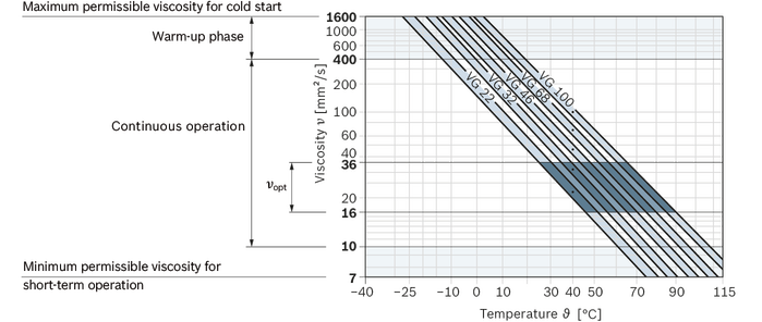
The hydraulic fluid should be selected so that the operating viscosity in the operating temperature range is within the optimum range (νopt; see selection diagram).
Viscosity | Shaft | Temperature1) | Comment | |
Cold start | νmax ≤ 1600 mm²/s | FKM | ϑSt ≥ -25 °C | t ≤ 3 min, without load (p ≤ 50 bar), n ≤ 1000 rpm, |
Warm-up phase | ν = 400 … 1600 mm²/s | t ≤ 15 min, p ≤ 0.7 • pnom and n ≤ 0.5 • nnom | ||
Continuous operation | ν = 10 … 400 mm²/s2) | FKM | ϑ ≤ +110 °C | measured at port L |
νopt = 16 … 36 mm²/s | range of optimum operating viscosity and efficiency | |||
Short-term operation | νmin = 7 … 10 mm²/s | FKM | ϑ ≤ +110 °C | t ≤ 3 min, p ≤ 0.3 • pnom measured at port L |
| 1) | If the specified temperatures cannot be maintained due to extreme operating parameters, please contact us. |
| 2) | Equates e.g. with the VG 46 a temperature range of +5 °C to +85 °C (see selection diagram) |
Notice
For applications in the low-temperature range down to -40°C, please contact us.
Finer filtration improves the cleanliness level of the hydraulic fluid, which increases the service life of the axial piston unit.
A cleanliness level of at least 20/18/15 is to be maintained according to ISO 4406.
At a hydraulic fluid viscosity of less than 10 mm²/s (e.g. due to high temperatures in short-term operation) at the drain port, a cleanliness level of at least 19/17/14 according to ISO 4406 is required.
For example, the viscosity is 10 mm²/s at:
HLP 32 a temperature of 73°C
HLP 46 a temperature of 85°C
Pressure at working port B | Definition | ||
Nominal pressure | pnom | 280 bar | The nominal pressure corresponds to the maximum design pressure. |
Maximum pressure | pmax | 350 bar | The maximum pressure corresponds to the maximum operating pressure within the single operating period. The sum of the single operating periods must not exceed the total operating period. |
Single operating period | 2.5 ms | ||
Total operating period | 300 h | ||
Minimum pressure | pB abs | 20 bar | Minimum pressure on the high-pressure side (port B) which is required in order to prevent damage to the axial piston unit. |
Reversing pressure (high-pressure side) | pRev abs | <50 bar | The Δ pressure between A and B at which the system switches from fan operation to reversing operation and then from reversing operation back to fan mode is between 30 to 45 bar relative. The pressure in B must be less than 50 bar. |
Rate of pressure change | RA max | 16000 bar/s | Maximum permissible rate of pressure build-up and reduction during a pressure change over the entire pressure range. |
Pressure at the low-pressure port A | Definition | ||
Minimum pressure | pND min | 2 bar absolute | Minimum pressure at the low-pressure port A (outlet) that is required in order to avoid damage to the axial piston unit. |
Maximum pressure | pND max | 30 bar absolute | |
Case pressure at port L | Definition | ||
Maximum pressure Operation as a motor, open circuit | pL max | 2 bar | |
Working pressure range applies when using mineral oil-based hydraulic fluids. Please contact us for values for other hydraulic fluids.
In addition to the hydraulic fluid and the temperature, the service life of the shaft seal is influenced by the rotational speed of the axial piston unit and the case pressure.
The case pressure must be greater than the ambient pressure.

| 1) | Total operating period = t1 + t2 + ... + tn |

Motor direction of rotation with unchanged pressure side B | at Vg max + | at Vg max - |
(de-energized) clockwise | B to A | |
(energized) counter-clockwise | B to A |
Size | 18 | 23 | 28 | 37 | 45 | |||
Maximum radial force |  | Fq max | N | 1200 | 1200 | 1200 | 1500 | 1500 |
Maximum axial force |  | - Fax max | N | 1000 | 1000 | 1000 | 1500 | 1500 |
Notice
The values given are maximum values and do not apply to continuous operation.
For output drives with radial loading, please contact us.
Size | 18 | 23 | 28 | 37 | 45 | |||
Displacement | +100 % Vg max | cm³ | 18 | 23 | 28 | 37 | 45 | |
-100 % Vg max | cm³ | 18 | 23 | 28 | 37 | 45 | ||
Nominal pressure | pnom | bar | 280 | 280 | 280 | 280 | 280 | |
Maximum pressure | pmax | bar | 350 | 350 | 350 | 350 | 350 | |
Rotational speed 1) | maximum, at Vg max | nnom | rpm | 3000 | 3000 | 3000 | 2200 | 2000 |
minimum, at permanent operation | nmin | rpm | 250 | 250 | 250 | 250 | 250 | |
Torque | at Vg max and pnom | M | Nm | 80 | 102 | 125 | 165 | 200 |
Rotary stiffness of drive shaft | C | c | kNm/rad | 24.16 | 24.16 | 24.16 | 32.38 | 32.38 |
Y | c | kNm/rad | 24.16 | 24.16 | 24.16 | 32.38 | 32.38 | |
Moment of inertia for rotary group | JTW | kg·m² | 0.0017 | 0.0017 | 0.0017 | 0.0033 | 0.0033 | |
Maximum angular acceleration 2) | a | rad/s² | 5500 | 5500 | 5500 | 4000 | 4000 | |
Case volume | V | l | 0.6 | 0.6 | 0.6 | 0.7 | 0.7 | |
Weight (approx.) | m | kg | 14 | 14 | 14 | 18 | 18 | |
| 1) | These values are valid at: - an absolute pressure of pabs = 2 bar at low-pressure port A - for the optimum viscosity range from vopt = 36 to 16 mm2/s - with hydraulic fluid based on mineral oils |
| 2) | The data are valid for values between the minimum required and maximum permissible rotational speed. It applies for external stimuli (e.g. diesel engine 2 to 8 times rotary frequency, cardan shaft twice the rotary frequency). The limit value is only valid for a single pump. The load capacity of the connection parts must be considered. |
Notice
The table values are theoretical values without consideration of efficiencies and tolerances. The values are rounded.
Operation above the maximum values or below the minimum values may result in a loss of function, a reduced service life or in the destruction of the axial piston unit.
Bosch Rexroth recommends testing the loads by means of experiment or calculation / simulation and comparison with the permissible values.
Determining the operating characteristics | ||
Inlet flow | | [l/min] |
Rotational speed | | [rpm] |
Torque | | [Nm] |
Power | | [kW] |
Key | |
Vg | Displacement per revolution [cm3] |
Δp | Differential pressure [bar] |
n | Rotational speed [rpm] |
ηv | Volumetric efficiency |
ηhm | Hydraulic-mechanical efficiency |
ηt | Total efficiency (ηt = ηv • ηhm) |
The axial piston unit is designed for operation with HLP mineral oil according to DIN 51524. See the following data sheet for application instructions and requirements for selecting hydraulic fluid, behavior during operation as well as disposal and environmental protection before you begin project planning:
Bosch Rexroth evaluates hydraulic fluids on the basis of the Fluid Rating according to the technical data sheet 90235.
Hydraulic fluids with positive evaluation in the Fluid Rating are provided in the following technical data sheet:
The hydraulic fluid should be selected so that the operating viscosity in the operating temperature range is within the optimum range (νopt; see selection diagram).
Viscosity | Shaft | Temperature1) | Comment | |
Cold start | νmax ≤ 1600 mm²/s | FKM | ϑSt ≥ -25 °C | t ≤ 3 min, without load (p ≤ 50 bar), n ≤ 1000 rpm, |
Warm-up phase | ν = 400 … 1600 mm²/s | t ≤ 15 min, p ≤ 0.7 • pnom and n ≤ 0.5 • nnom | ||
Continuous operation | ν = 10 … 400 mm²/s2) | FKM | ϑ ≤ +110 °C | measured at port L |
νopt = 16 … 36 mm²/s | range of optimum operating viscosity and efficiency | |||
Short-term operation | νmin = 7 … 10 mm²/s | FKM | ϑ ≤ +110 °C | t ≤ 3 min, p ≤ 0.3 • pnom measured at port L |
| 1) | If the specified temperatures cannot be maintained due to extreme operating parameters, please contact us. |
| 2) | Equates e.g. with the VG 46 a temperature range of +5 °C to +85 °C (see selection diagram) |
Notice
For applications in the low-temperature range down to -40°C, please contact us.
Finer filtration improves the cleanliness level of the hydraulic fluid, which increases the service life of the axial piston unit.
A cleanliness level of at least 20/18/15 is to be maintained according to ISO 4406.
At a hydraulic fluid viscosity of less than 10 mm²/s (e.g. due to high temperatures in short-term operation) at the drain port, a cleanliness level of at least 19/17/14 according to ISO 4406 is required.
For example, the viscosity is 10 mm²/s at:
HLP 32 a temperature of 73°C
HLP 46 a temperature of 85°C
Pressure at working port B | Definition | ||
Nominal pressure | pnom | 280 bar | The nominal pressure corresponds to the maximum design pressure. |
Maximum pressure | pmax | 350 bar | The maximum pressure corresponds to the maximum operating pressure within the single operating period. The sum of the single operating periods must not exceed the total operating period. |
Single operating period | 2.5 ms | ||
Total operating period | 300 h | ||
Minimum pressure | pB abs | 20 bar | Minimum pressure on the high-pressure side (port B) which is required in order to prevent damage to the axial piston unit. |
Reversing pressure (high-pressure side) | pRev abs | <50 bar | The Δ pressure between A and B at which the system switches from fan operation to reversing operation and then from reversing operation back to fan mode is between 30 to 45 bar relative. The pressure in B must be less than 50 bar. |
Rate of pressure change | RA max | 16000 bar/s | Maximum permissible rate of pressure build-up and reduction during a pressure change over the entire pressure range. |
Pressure at the low-pressure port A | Definition | ||
Minimum pressure | pND min | 2 bar absolute | Minimum pressure at the low-pressure port A (outlet) that is required in order to avoid damage to the axial piston unit. |
Maximum pressure | pND max | 30 bar absolute | |
Case pressure at port L | Definition | ||
Maximum pressure Operation as a motor, open circuit | pL max | 2 bar | |
Working pressure range applies when using mineral oil-based hydraulic fluids. Please contact us for values for other hydraulic fluids.
In addition to the hydraulic fluid and the temperature, the service life of the shaft seal is influenced by the rotational speed of the axial piston unit and the case pressure.
The case pressure must be greater than the ambient pressure.
| 1) | Total operating period = t1 + t2 + ... + tn |
Motor direction of rotation with unchanged pressure side B | at Vg max + | at Vg max - |
(de-energized) clockwise | B to A | |
(energized) counter-clockwise | B to A |
Size | 18 | 23 | 28 | 37 | 45 | |||
Maximum radial force | | Fq max | N | 1200 | 1200 | 1200 | 1500 | 1500 |
Maximum axial force | | - Fax max | N | 1000 | 1000 | 1000 | 1500 | 1500 |
Notice
The values given are maximum values and do not apply to continuous operation.
For output drives with radial loading, please contact us.

| 1) | Additional sizes available on request |
| 2) | Additional directions of rotation available on request |
| 3) | Specify type code of sensor DSM according to data sheet 95132 and/or DSA 95133 separately and observe the requirements on the electronics. |
Notice
Observe the information in the project planning notes chapter.
Please note the information on project planning and commissioning of the axial piston variable motor A10VER in the project planning instructions 90363.
In addition to the type code, please specify the relevant technical data when placing your order.
Size | 18 | 23 | 28 | ||
A | Working port (high-pressure series) | Size | 3/4 in | ||
Standard 1) | SAE J518 | ||||
Fastening thread 2) | M10 × 15; 17 mm deep | ||||
State on delivery | With protective cover (must be connected) | ||||
B | Working port (high-pressure series) | Size | 3/4 in | ||
Standard 1) | SAE J518 | ||||
Fastening thread 2) | M10 × 15; 17 mm deep | ||||
State on delivery | With protective cover (must be connected) | ||||
L or L1 | Drain port | Size | 3/4-16UNF-2B; 15 mm deep | ||
Standard 3) | ISO 11926 | ||||
State on delivery | With protective cover (observe installation instructions) | ||||
| 1) | Metric fastening thread is a deviation from standard. |
| 2) | Thread according to DIN 13 |
| 3) | The spot face can be deeper than specified in the appropriate standard. |
Size | 18 | 23 | 28 | ||
A | Working port (high-pressure series) | Size | 3/4 in | ||
Standard | SAE J518 | ||||
Fastening thread 1) | 3/8-16UNC-2B; 21 mm deep | ||||
State on delivery | With protective cover (must be connected) | ||||
B | Working port (high-pressure series) | Size | 3/4 in | ||
Standard | SAE J518 | ||||
Fastening thread 1) | 3/8-16UNC-2B; 21 mm deep | ||||
State on delivery | With protective cover (must be connected) | ||||
L or L1 | Drain port | Size | 3/4-16UNF-2B; 15 mm deep | ||
Standard 2) | ISO 11926 | ||||
State on delivery | With protective cover (observe installation instructions) | ||||
| 1) | Thread according to ASME B1.1 |
| 2) | The spot face can be deeper than specified in the appropriate standard. |
Size | 37 | 45 | ||
A | Working port (high-pressure series) | Size | 3/4 in | |
Standard 1) | SAE J518 | |||
Fastening thread 2) | M10 × 15; 17 mm deep | |||
State on delivery | With protective cover (must be connected) | |||
B | Working port (high-pressure series) | Size | 3/4 in | |
Standard 1) | SAE J518 | |||
Fastening thread 2) | M10 × 15; 17 mm deep | |||
State on delivery | With protective cover (must be connected) | |||
L | Drain port | Size | 7/8-14UNF-2B; 17 mm deep | |
Standard 3) | ISO 11926 | |||
State on delivery | With protective cover (observe installation instructions) | |||
| 1) | Metric fastening thread is a deviation from standard. |
| 2) | Thread according to DIN 13 |
| 3) | The spot face can be deeper than specified in the appropriate standard. |
Size | 37 | 45 | ||
A | Working port (high-pressure series) | Size | 3/4 in | |
Standard | SAE J518 | |||
Fastening thread 1) | 3/8-16UNC-2B; 21 mm deep | |||
State on delivery | With protective cover (must be connected) | |||
B | Working port (high-pressure series) | Size | 3/4 in | |
Standard | SAE J518 | |||
Fastening thread 1) | 3/8-16UNC-2B; 21 mm deep | |||
State on delivery | With protective cover (must be connected) | |||
L | Drain port | Size | 7/8-14UNF-2B; 17 mm deep | |
Standard 2) | ISO 11926 | |||
State on delivery | With protective cover (observe installation instructions) | |||
| 1) | Thread according to ASME B1.1 |
| 2) | The spot face can be deeper than specified in the appropriate standard. |
Size | 18 | 23 | 28 | ||
A | Working port (high-pressure series) | Size | 3/4 in | ||
Standard 1) | SAE J518 | ||||
Fastening thread 2) | M10 × 15; 17 mm deep | ||||
State on delivery | With protective cover (must be connected) | ||||
B | Working port (high-pressure series) | Size | 3/4 in | ||
Standard 1) | SAE J518 | ||||
Fastening thread 2) | M10 × 15; 17 mm deep | ||||
State on delivery | With protective cover (must be connected) | ||||
L or L1 | Drain port | Size | 3/4-16UNF-2B; 15 mm deep | ||
Standard 3) | ISO 11926 | ||||
State on delivery | With protective cover (observe installation instructions) | ||||
| 1) | Metric fastening thread is a deviation from standard. |
| 2) | Thread according to DIN 13 |
| 3) | The spot face can be deeper than specified in the appropriate standard. |
Size | 18 | 23 | 28 | ||
A | Working port (high-pressure series) | Size | 3/4 in | ||
Standard | SAE J518 | ||||
Fastening thread 1) | 3/8-16UNC-2B; 21 mm deep | ||||
State on delivery | With protective cover (must be connected) | ||||
B | Working port (high-pressure series) | Size | 3/4 in | ||
Standard | SAE J518 | ||||
Fastening thread 1) | 3/8-16UNC-2B; 21 mm deep | ||||
State on delivery | With protective cover (must be connected) | ||||
L or L1 | Drain port | Size | 3/4-16UNF-2B; 15 mm deep | ||
Standard 2) | ISO 11926 | ||||
State on delivery | With protective cover (observe installation instructions) | ||||
| 1) | Thread according to ASME B1.1 |
| 2) | The spot face can be deeper than specified in the appropriate standard. |
Size | 37 | 45 | ||
A | Working port (high-pressure series) | Size | 3/4 in | |
Standard 1) | SAE J518 | |||
Fastening thread 2) | M10 × 15; 17 mm deep | |||
State on delivery | With protective cover (must be connected) | |||
B | Working port (high-pressure series) | Size | 3/4 in | |
Standard 1) | SAE J518 | |||
Fastening thread 2) | M10 × 15; 17 mm deep | |||
State on delivery | With protective cover (must be connected) | |||
L | Drain port | Size | 7/8-14UNF-2B; 17 mm deep | |
Standard 3) | ISO 11926 | |||
State on delivery | With protective cover (observe installation instructions) | |||
| 1) | Metric fastening thread is a deviation from standard. |
| 2) | Thread according to DIN 13 |
| 3) | The spot face can be deeper than specified in the appropriate standard. |
Size | 37 | 45 | ||
A | Working port (high-pressure series) | Size | 3/4 in | |
Standard | SAE J518 | |||
Fastening thread 1) | 3/8-16UNC-2B; 21 mm deep | |||
State on delivery | With protective cover (must be connected) | |||
B | Working port (high-pressure series) | Size | 3/4 in | |
Standard | SAE J518 | |||
Fastening thread 1) | 3/8-16UNC-2B; 21 mm deep | |||
State on delivery | With protective cover (must be connected) | |||
L | Drain port | Size | 7/8-14UNF-2B; 17 mm deep | |
Standard 2) | ISO 11926 | |||
State on delivery | With protective cover (observe installation instructions) | |||
| 1) | Thread according to ASME B1.1 |
| 2) | The spot face can be deeper than specified in the appropriate standard. |


