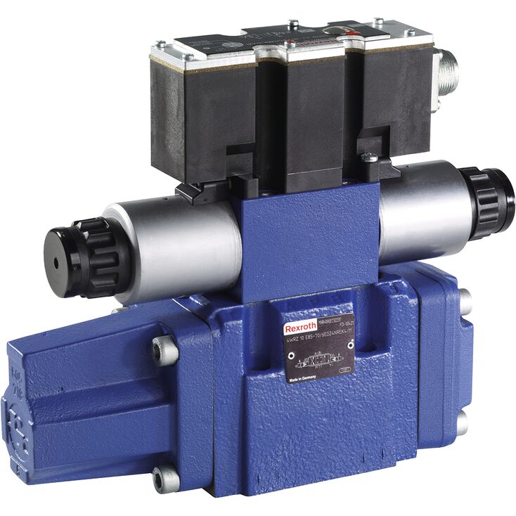
4WRZE 16 W6-150-7X/6EG24N9ETK31/A1D3M
Rexroth
R900977490
带集成电子装置(OBE)的两级先导式比例换向阀。
控制液流的方向与大小。
由带中心螺纹及可拆卸线圈的比例电磁铁驱动。
用于底板安装,油口布置符合ISO 4401。
可选辅助操纵装置。
弹簧对中的控制阀芯。
4WRZ(E)...型阀为比例电磁铁驱动的先导式四通阀,用于控制流向及流量大小。
5WRZ(E)...型阀另设“R”口,仅适用于NG52。
该阀主要组成如下:
先导控制阀(9),带比例电磁铁(5 和 6)
主阀(10),带主阀芯(11)和对中弹簧(12)
电磁铁(5、6)断电时,对中弹簧(12)使主阀芯(11)保持中位。
主阀芯(11)由先导控制阀(9)控制,例如激励电磁铁“b”(6),使主阀芯按比例移动。
→ 控制阀芯(2)向右移动,先导油经先导控制阀(9)进入压力腔(13),使主阀芯(11)按电气输入信号的比例偏移。
→ P至A、B至T通过孔口式控制截面接通,具有渐进流量特性。
先导控制阀可通过 P 口内部供油,也可通过 X 口外部供油
电磁铁(6)断电
→ 控制阀芯(2)及主阀芯(11)返回中位。
根据阀芯位置,油液由 P 流向 A、由 B 流向 T,或由 P 流向 B、由 A 流向 T(R)
可选的手动应急操作装置(14 和 15)可在电磁铁未通电时移动控制阀芯(2)。
意外触发手动应急操作装置可能导致机器发生不受控的运动!
由于结构原理所限,阀存在固有的内泄漏,且内泄漏可能在使用周期内增加。
01 | 02 | 03 | 04 | 05 | 06 | 07 | 08 | 09 | 10 | 11 | 12 | 13 | 14 | 15 | 16 | ||
4 | WRZ | ‒ | 7X | / | 6E | G24 | * |
01 | 4 main ports | 4 |
02 | Proportional directional valve with electro-hydraulic operation and external electronics | WRZ |
03 | Size 10 | 10 |
Size 16 | 16 | |
Size 25 | 25 | |
Size 32 | 32 | |
Size 52 | 52 | |
04 | Symbols; for the possible version, see "Symbols/Circuit diagrams" | E; E1-; E3-; W6-; W8-; W9-; EA; W6A |
Rated flow NG10 | ||
05 | 25 l/min | 25 |
50 l/min | 50 | |
90 l/min | 85 | |
Rated flow NG16 | ||
05 | 100 l/min | 100 |
125 l/min | 125 | |
150 l/min | 150 | |
180 l/min | 180 | |
Rated flow NG25 | ||
05 | 220 l/min | 220 |
325 l/min | 325 | |
Rated flow NG32 | ||
05 | 360 l/min | 360 |
520 l/min | 520 | |
Rated flow NG52 | ||
05 | 1000 l/min | 1000 |
06 | Component series 70 ... 79 (70 ... 79: unchanged installation and connection dimensions) | 7X |
07 | For subplate mounting | no code |
For flange connection (only NG 52) | F | |
08 | Pilot control valve NG6 | 6E |
09 | Supply voltage 24 V | G24 |
10 | Without manual override | no code |
With concealed manual override | N9 1) | |
11 | Without special type of protection | no code |
Sea water-resistant | J 2) | |
Pilot oil supply and return | ||
12 | External pilot oil supply, external pilot oil return | no code |
Internal pilot oil supply, external pilot oil return | E | |
Pilot oil supply internal, pilot oil return internal | ET | |
External pilot oil supply, internal pilot oil return | T | |
Electrical connection | ||
13 | Without mating connector, with connector according to DIN EN 175301-803, separate order | K43) |
Without mating connector, connector according to DIN EN 175201-804 | K31 3) | |
14 | Without pressure reducing valve | no code |
With pressure reducing valve ZDR 6 DP0-4X/40YM-W80 (fixedly set) | D3 | |
15 | NBR seals | M |
FKM seals | V | |
16 | Further details in the plain text | * |
1) | With version “J” → “N” instead of “N9” | |
2) | For data regarding the seawater-resistant version refer to data sheet 29115-M | |
3) | For version "J" = seawater-resistant only "K31" | |
Type | 4WREE | ||
Size | 6 | 10 | |
Installation position | any, preferably horizontal | ||
Ambient temperature range | °C | -20 … +50 | |
Storage temperature range | °C | -20 … +80 | |
Weight | kg | 2.4 | 6.5 |
MTTFD values according to EN ISO 13849 1) | y | 150 | |
| 1) | With control spool types E, E1, EA, W, W1, WA; in longitudinal control spool direction, there is sufficient positive overlap without shock/vibration load; observe the installation orientation with regard to the main direction of acceleration. |
Size | 6 | 10 | ||
Maximum operating pressure | bar | 315 | ||
Maximum operating pressure | Port P | bar | 315 | |
Port T | bar | 210 | ||
Anschluss A | bar | 315 | ||
Port B | bar | 315 | ||
Maximum flow | l/min | 80 | 180 | |
Nominal flow | l/min | 4 8 16 32 | 25 50 75 | |
Hydraulic fluid | see table below | |||
Hydraulic fluid temperature range | °C | -20 … +80 | ||
preferably | °C | +40 … +50 | ||
Viscosity range | mm²/s | 20 … 380 | ||
preferably | mm²/s | 30 … 46 | ||
Maximum admissible degree of contamination of the hydraulic fluid, cleanliness class according to ISO 4406 (c) 1) | Class 20/18/15 according to ISO 4406 (c) | |||
Hysteresis | % | ≤ 0.1 | ||
Range of inversion | % | ≤ 0.05 | ||
Response sensitivity | % | ≤ 0.05 | ||
Zero shift upon change of | Hydraulic fluid temperature | %/10 K | ≤ 0.15 | |
Operating pressure | %/100 bar | ≤ 0.1 | ||
| 1) | The cleanliness classes specified for the components must be adhered to in hydraulic systems. Effective filtration prevents faults and simultaneously increases the life cycle of the components. For the selection of the filters, see www.boschrexroth.com/filter. |
Hydraulic fluid | Classification | Suitable sealing materials | Standards |
Mineral oils and related hydrocarbons | HL, HLP | NBR / FKM | DIN 51524 |
Flame-resistant - containing water | HFC (Fuchs HYDROTHERM 46M, Petrofer Ultra Safe 620) | NBR | ISO 12922 |
Important information on hydraulic fluids: For more information and data on the use of other hydraulic fluids please contact us. There may be limitations regarding the technical valve data (temperature, pressure range, life cycle, maintenance intervals, etc.). The flash point of the process and operating medium used must be 40 K over the maximum solenoid surface temperature. Flame-resistant - containing water: | |||
Size | 6 | 10 | ||
Voltage type | Direct voltage | |||
Maximum current consumption | of the amplifier | A | 2 | |
of the amplifier (impulse current) | A | 3 | ||
Solenoid coil resistance | Cold value at 20 °C | Ω | 2.65 | 4.55 |
Maximum hot value | Ω | 4.05 | 6.82 | |
Actuated time | % | 100 | ||
Maximum coil temperature 1) | °C | 150 | ||
Protection class according to DIN EN 60529 | IP65 (If a suitable and a correctly mounted mating connector are used.) | |||
Power supply | V | 24 | ||
Supply voltage range | V | 19,4 … 35 | ||
Earthing (GND) | V | 0 | ||
Command value input | "A1" | V | ± 10 | |
Command value input range | "F1" | mA | 4 … 20 | |
Actual value output | "A1" | V | ± 10 | |
Actual value output range | "F1" | mA | 4 … 20 | |
| 1) | Due to the surface temperatures occurring at solenoid coils, the European standards ISO 13732-1 and ISO 4413 need to be adhered to. |
规格 10
规格 10
规格 10
规格 10
规格 16
规格 16
规格 16
规格 16
规格 16
NG25
NG25
NG25
规格 32
规格 32
规格 32
NG52
NG52