| Availability: | |
|---|---|
| Quantity: | |

4WRZE 16 W6-150-7X/6EG24N9ETK31/A1D3M
Rexroth
R900977490
Pilot-operated, 2-stage proportional directional valves with integrated electronics (OBE)
Control of the direction and magnitude of a flow
Operation by means of proportional solenoids with central thread and detachable coil
For subplate mounting: Porting pattern according to ISO 4401
Optional auxiliary operating device
Spring-centered control spool
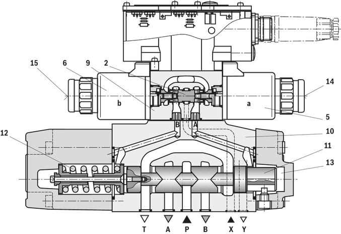
Valves of type 4WRZ(E)... are pilot-operated 4-directional valves that are actuated by means of proportional solenoids. Their function is to control the flow direction and size.
Valves of type 5WRZ(E)... are equipped with an additional port "R" (only NG52).
The valve basically consists of:
Pilot control valve (9) with proportional solenoids (5 and 6)
Main valve (10) with main control spool (11) and centering spring (12)
With de-energized solenoids (5, 6), the main control spool (11) is held in the central position by means of the centering spring (12)
The main control spool (11) is controlled by the pilot control valve (9); the main control spool is proportionally moved, e.g. by actuating solenoid "b" (6)
→ The control spool (2) is moved to the right, pilot oil enters the pressure chamber (13) via the pilot control valve (9) and deflects the main control spool (11) proportionally to the electric input signal
→ Connection from P to A and B to T via orifice-type cross-sections with progressive flow characteristics
Pilot oil supply to the pilot control valve internally via port P or externally via port X
Switching off the solenoid (6)
→ The control spool (2) and main control spool (11) are moved back into the central position
Depending on the spool position, flow occurs from P to A and B to T or P to B and A to T (R)
An optional manual override (14 and 15) can be used to move the control spool (2) without solenoid energization.
Accidental activation of the manual override may lead to uncontrolled machine movements!
Due to the design principle, internal leakage which may increase over the life cycle is inherent to the valves.
01 | 02 | 03 | 04 | 05 | 06 | 07 | 08 | 09 | 10 | 11 | 12 | 13 | 14 | 15 | 16 | ||
4 | WRZ | ‒ | 7X | / | 6E | G24 | * |
01 | 4 main ports | 4 |
02 | Proportional directional valve with electro-hydraulic operation and external electronics | WRZ |
03 | Size 10 | 10 |
Size 16 | 16 | |
Size 25 | 25 | |
Size 32 | 32 | |
Size 52 | 52 | |
04 | Symbols; for the possible version, see "Symbols/Circuit diagrams" | E; E1-; E3-; W6-; W8-; W9-; EA; W6A |
Rated flow NG10 | ||
05 | 25 l/min | 25 |
50 l/min | 50 | |
90 l/min | 85 | |
Rated flow NG16 | ||
05 | 100 l/min | 100 |
125 l/min | 125 | |
150 l/min | 150 | |
180 l/min | 180 | |
Rated flow NG25 | ||
05 | 220 l/min | 220 |
325 l/min | 325 | |
Rated flow NG32 | ||
05 | 360 l/min | 360 |
520 l/min | 520 | |
Rated flow NG52 | ||
05 | 1000 l/min | 1000 |
06 | Component series 70 ... 79 (70 ... 79: unchanged installation and connection dimensions) | 7X |
07 | For subplate mounting | no code |
For flange connection (only NG 52) | F | |
08 | Pilot control valve NG6 | 6E |
09 | Supply voltage 24 V | G24 |
10 | Without manual override | no code |
With concealed manual override | N9 1) | |
11 | Without special type of protection | no code |
Sea water-resistant | J 2) | |
Pilot oil supply and return | ||
12 | External pilot oil supply, external pilot oil return | no code |
Internal pilot oil supply, external pilot oil return | E | |
Pilot oil supply internal, pilot oil return internal | ET | |
External pilot oil supply, internal pilot oil return | T | |
Electrical connection | ||
13 | Without mating connector, with connector according to DIN EN 175301-803, separate order | K43) |
Without mating connector, connector according to DIN EN 175201-804 | K31 3) | |
14 | Without pressure reducing valve | no code |
With pressure reducing valve ZDR 6 DP0-4X/40YM-W80 (fixedly set) | D3 | |
15 | NBR seals | M |
FKM seals | V | |
16 | Further details in the plain text | * |
1) | With version “J” → “N” instead of “N9” | |
2) | For data regarding the seawater-resistant version refer to data sheet 29115-M | |
3) | For version "J" = seawater-resistant only "K31" | |
Type | 4WREE | ||
Size | 6 | 10 | |
Installation position | any, preferably horizontal | ||
Ambient temperature range | °C | -20 … +50 | |
Storage temperature range | °C | -20 … +80 | |
Weight | kg | 2.4 | 6.5 |
MTTFD values according to EN ISO 13849 1) | y | 150 | |
| 1) | With control spool types E, E1, EA, W, W1, WA; in longitudinal control spool direction, there is sufficient positive overlap without shock/vibration load; observe the installation orientation with regard to the main direction of acceleration. |
Size | 6 | 10 | ||
Maximum operating pressure | bar | 315 | ||
Maximum operating pressure | Port P | bar | 315 | |
Port T | bar | 210 | ||
Anschluss A | bar | 315 | ||
Port B | bar | 315 | ||
Maximum flow | l/min | 80 | 180 | |
Nominal flow | l/min | 4 8 16 32 | 25 50 75 | |
Hydraulic fluid | see table below | |||
Hydraulic fluid temperature range | °C | -20 … +80 | ||
preferably | °C | +40 … +50 | ||
Viscosity range | mm²/s | 20 … 380 | ||
preferably | mm²/s | 30 … 46 | ||
Maximum admissible degree of contamination of the hydraulic fluid, cleanliness class according to ISO 4406 (c) 1) | Class 20/18/15 according to ISO 4406 (c) | |||
Hysteresis | % | ≤ 0.1 | ||
Range of inversion | % | ≤ 0.05 | ||
Response sensitivity | % | ≤ 0.05 | ||
Zero shift upon change of | Hydraulic fluid temperature | %/10 K | ≤ 0.15 | |
Operating pressure | %/100 bar | ≤ 0.1 | ||
| 1) | The cleanliness classes specified for the components must be adhered to in hydraulic systems. Effective filtration prevents faults and simultaneously increases the life cycle of the components. For the selection of the filters, see www.boschrexroth.com/filter. |
Hydraulic fluid | Classification | Suitable sealing materials | Standards |
Mineral oils and related hydrocarbons | HL, HLP | NBR / FKM | DIN 51524 |
Flame-resistant - containing water | HFC (Fuchs HYDROTHERM 46M, Petrofer Ultra Safe 620) | NBR | ISO 12922 |
Important information on hydraulic fluids: For more information and data on the use of other hydraulic fluids please contact us. There may be limitations regarding the technical valve data (temperature, pressure range, life cycle, maintenance intervals, etc.). The flash point of the process and operating medium used must be 40 K over the maximum solenoid surface temperature. Flame-resistant - containing water: | |||
Size | 6 | 10 | ||
Voltage type | Direct voltage | |||
Maximum current consumption | of the amplifier | A | 2 | |
of the amplifier (impulse current) | A | 3 | ||
Solenoid coil resistance | Cold value at 20 °C | Ω | 2.65 | 4.55 |
Maximum hot value | Ω | 4.05 | 6.82 | |
Actuated time | % | 100 | ||
Maximum coil temperature 1) | °C | 150 | ||
Protection class according to DIN EN 60529 | IP65 (If a suitable and a correctly mounted mating connector are used.) | |||
Power supply | V | 24 | ||
Supply voltage range | V | 19,4 … 35 | ||
Earthing (GND) | V | 0 | ||
Command value input | "A1" | V | ± 10 | |
Command value input range | "F1" | mA | 4 … 20 | |
Actual value output | "A1" | V | ± 10 | |
Actual value output range | "F1" | mA | 4 … 20 | |
| 1) | Due to the surface temperatures occurring at solenoid coils, the European standards ISO 13732-1 and ISO 4413 need to be adhered to. |
Size 10
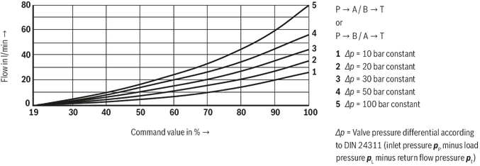
Size 10
Size 10
Size 10

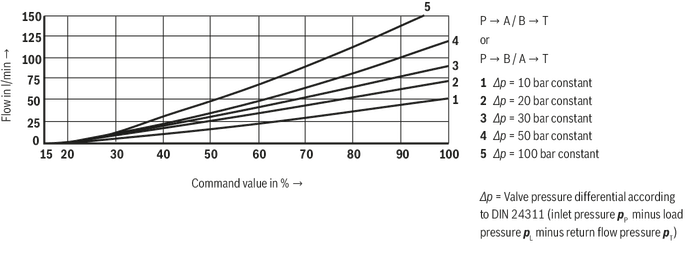
Size 16

Size 16

Size 16
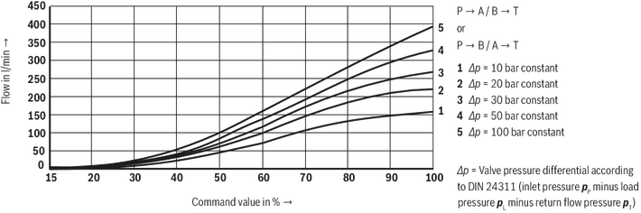
Size 16
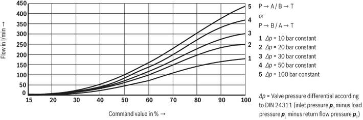
Size 16

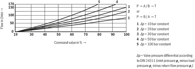
NG25
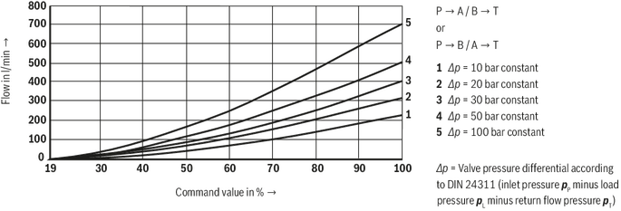
NG25
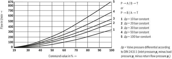
NG25

Size 32

Size 32

Size 32

NG52

NG52

Size 10
Size 10
Size 10
Size 10
Size 16
Size 16
Size 16
Size 16
Size 16
NG25
NG25
NG25
Size 32
Size 32
Size 32
NG52
NG52


