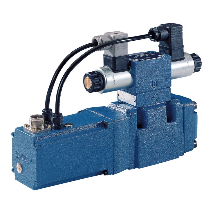
4WRKE 10 E100L-3X/6EG24ETK31/A1D3M
Rexroth
R900704216
两级先导式比例换向阀,主阀芯带电气位置反馈,并配集成电子装置(OBE)。
控制流向及流量大小。
比例电磁铁驱动。
用于底板安装,油口布置符合ISO 4401。
电气位置反馈。
弹簧对中的主阀芯。
先导控制阀为单级比例换向阀。
主级带位置闭环控制。
先导控制阀是直动式比例阀,其控制边几何形状针对4WRKE比例换向阀的先导控制用途进行了优化。比例电磁铁为耐压密封的湿式直流电磁铁,线圈可拆卸,可将电流按比例转换为机械力。电流增加时,电磁力相应增大;设定的电磁力在整个控制行程中保持恒定。
先导阀主要由阀体(1)、比例电磁铁(2、3)、控制阀芯(4)及弹簧(5、6)组成。未动作时两个执行端均与油箱相连。激励其中一个电磁铁(2或3)后,电磁力使阀芯(4)朝弹簧(5或6)移动。越过遮盖区后,封闭其中一个执行端至油箱的连接,同时接通压力腔,使油液由P流向主级控制腔。
4WRKE型阀为两级比例换向阀,控制流向及流量。主级采用位置闭环控制,因此即使流量较大,阀芯位置也不受液动力影响。
该阀主要由先导阀(1)、阀体(8)、主阀芯(7)、盖板(5、6)、对中弹簧(4)、感应式位置传感器(9)及减压阀(3)组成。无输入信号时,对中弹簧(4)使主阀芯保持中位,盖板内两个控制腔经先导阀芯(2)与油箱相通。主阀芯通过位置传感器连接至匹配的控制电子装置。主阀芯位置变化与放大器加法节点处指令值变化均会产生电压差。电子装置比较指令值与实际值,确定控制偏差,向先导阀(1)的比例电磁铁供电。电流产生电磁力,经推杆驱动阀芯,通过控制截面的液流调节主阀芯。主阀芯(7)及其连接的位置传感器铁芯移动,直至实际值与指令值相符。稳定控制时,主阀芯受力平衡并保持相应位置。阀芯行程与开口随指令值成比例变化。控制电子装置集成于阀内,阀与电子装置配套调整,使批量产品偏差较小。
不得使回油管路排空;相应安装条件下必须安装预紧阀,预紧压力约2 bar。
第二级基本由本公司比例阀模块组成。“主级零点”已在工厂调整,可通过控制电子装置中的电位器,在额定行程的±30%范围内调整。拆下盖壳前侧的螺塞即可接近集成控制电子装置。更换先导阀或控制电子装置后,必须重新调整。所有调整只能由经过指导的专业人员进行。
零点的改变可能损坏系统,只能由经过指导的专业人员实施!
01 | 02 | 03 | 04 | 05 | 06 | 07 | 08 | 09 | 10 | 11 | 12 | 13 | 14 | 15 | 16 | ||
4 | WRZ | ‒ | 7X | / | 6E | G24 | * |
01 | 4 main ports | 4 |
02 | Proportional directional valve with electro-hydraulic operation and external electronics | WRZ |
03 | Size 10 | 10 |
Size 16 | 16 | |
Size 25 | 25 | |
Size 32 | 32 | |
Size 52 | 52 | |
04 | Symbols; for the possible version, see "Symbols/Circuit diagrams" | E; E1-; E3-; W6-; W8-; W9-; EA; W6A |
Rated flow NG10 | ||
05 | 25 l/min | 25 |
50 l/min | 50 | |
90 l/min | 85 | |
Rated flow NG16 | ||
05 | 100 l/min | 100 |
125 l/min | 125 | |
150 l/min | 150 | |
180 l/min | 180 | |
Rated flow NG25 | ||
05 | 220 l/min | 220 |
325 l/min | 325 | |
Rated flow NG32 | ||
05 | 360 l/min | 360 |
520 l/min | 520 | |
Rated flow NG52 | ||
05 | 1000 l/min | 1000 |
06 | Component series 70 ... 79 (70 ... 79: unchanged installation and connection dimensions) | 7X |
07 | For subplate mounting | no code |
For flange connection (only NG 52) | F | |
08 | Pilot control valve NG6 | 6E |
09 | Supply voltage 24 V | G24 |
10 | Without manual override | no code |
With concealed manual override | N9 1) | |
11 | Without special type of protection | no code |
Sea water-resistant | J 2) | |
Pilot oil supply and return | ||
12 | External pilot oil supply, external pilot oil return | no code |
Internal pilot oil supply, external pilot oil return | E | |
Pilot oil supply internal, pilot oil return internal | ET | |
External pilot oil supply, internal pilot oil return | T | |
Electrical connection | ||
13 | Without mating connector, with connector according to DIN EN 175301-803, separate order | K43) |
Without mating connector, connector according to DIN EN 175201-804 | K31 3) | |
14 | Without pressure reducing valve | no code |
With pressure reducing valve ZDR 6 DP0-4X/40YM-W80 (fixedly set) | D3 | |
15 | NBR seals | M |
FKM seals | V | |
16 | Further details in the plain text | * |
1) | With version “J” → “N” instead of “N9” | |
2) | For data regarding the seawater-resistant version refer to data sheet 29115-M | |
3) | For version "J" = seawater-resistant only "K31" | |
Type | 4WRKE | ||||||
Size | 10 | 16 | 25 | 27 | 32 | 35 | |
Installation position | any, preferably horizontal | ||||||
Ambient temperature range | °C | -20 … +50 | |||||
Storage temperature range | °C | -20 … +80 | |||||
Weight | kg | 8.7 | 11.2 | 16.8 | 17 | 31.5 | 34 |
Sine test according to DIN EN 60068-2-6 | 10 cycles, 10…2000.. 10 Hz with logarithmic frequency changing speed of 1 octave/min, 5 to 57 Hz, amplitude 1.5 mm (p-p), 57 to 2000 Hz, amplitude 10g, 3 axes | ||||||
Noise test according to DIN EN 60068-2-64 | 20…2000 Hz, amplitude 0.05g2/Hz (10gRMS) 3 axes, testing time 30 min per axis | ||||||
Shock test according to DIN EN 60068-2-27 | Half-sine 15g / 11 ms, 3 times in positive and 3 times in negative direction per axis, 3 axes | ||||||
Damp heat according to DIN EN 60068-2-30 | Variant 2: +25 °C … +55 °C, 90 % … 97 % relative humidity, 2 cycles á 24 hours | ||||||
Size | 10 | 16 | 25 | 27 | 32 | 35 | |||
Maximum operating pressure | bar | 350 | |||||||
Maximum operating pressure | Port P | bar | 315 | 350 | 210 | 350 | |||
Anschluss A | bar | 315 | 350 | 210 | 350 | ||||
Port B | bar | 315 | 350 | 210 | 350 | ||||
Operating pressure range | Pilot control valve, pilot oil supply | bar | 25 … 315 | ||||||
Maximum return flow pressure | Port T, external pilot oil return | bar | 315 | 250 | 210 | 250 | |||
Port T, internal pilot oil return | bar | 10 | |||||||
Port Y | bar | 10 | |||||||
Maximum flow | l/min | 170 | 460 | 870 | 1000 | 1600 | 3000 | ||
Nominal flow 1) | l/min | 25 50 100 | 125 150 200 220 | 220 350 | 500 | 400 600 | 1000 | ||
Pilot flow | input signal 0 → 100% | Port X and Y | l/min | 4.1 | 8.5 | 11.7 | 13 | ||
Hydraulic fluid temperature range | °C | -20 … +80 | |||||||
preferably | °C | -40 … +50 | |||||||
Viscosity range | mm²/s | 20 … 380 | |||||||
preferably | mm²/s | 30 … 45 | |||||||
Maximum admissible degree of contamination of the hydraulic fluid, cleanliness class according to ISO 4406 (c) 2) | Pilot control valve | Class 18/16/13 according to ISO 4406 (c) | |||||||
Main valve | Class 20/18/15 according to ISO 4406 (c) | ||||||||
Hysteresis | % | ≤ 1 | |||||||
Response sensitivity | % | ≤ 0.5 | |||||||
| 1) | ±10% with Δp = 10 bar, Δp = valve pressure differential |
| 2) | The cleanliness classes specified for the components must be adhered to in hydraulic systems. Effective filtration prevents faults and simultaneously increases the life cycle of the components. For the selection of the filters, see www.boschrexroth.com/filter. |
Size | 10 | 16 | 25 | 27 | 32 | 35 | ||
Voltage type | Direct voltage | |||||||
Type of signal | analog | |||||||
Maximum current consumption | of the amplifier | A | 1.5 | |||||
of the amplifier (impulse current) | A | 3 | ||||||
Protection class according to DIN EN 60529 | IP65 (If a suitable and a correctly mounted mating connector are used.) | |||||||
Power supply | V | 24 | ||||||
Supply voltage range | V | 18 … 35 | ||||||
Earthing (GND) | V | 0 | ||||||
Command value input | "A1" | V | 10 | |||||
Command value input range | "F1" | mA | 4 … 20 | |||||
Actual value output | "A1" | V | 10 | |||||
Actual value output range | "F1" | mA | 4 … 20 | |||||
Hydraulic fluid | Classification | Suitable sealing materials | Standards |
Mineral oils and related hydrocarbons | HL, HLP | NBR / FKM | DIN 51524 |
Flame-resistant - containing water | HFC (Fuchs HYDROTHERM 46M, Petrofer Ultra Safe 620) | NBR | ISO 12922 |
Phosphoric acid esters | HFD-R | FKM | |
Important information on hydraulic fluids: For more information and data on the use of other hydraulic fluids please contact us. There may be limitations regarding the technical valve data (temperature, pressure range, life cycle, maintenance intervals, etc.). The flash point of the process and operating medium used must be 40 K over the maximum solenoid surface temperature. Flame-resistant - containing water: | |||
特性曲线 L
特性曲线 P
规格 10
规格 10
规格 16
规格 16
规格 25、规格 27
规格 25、规格 27
规格 32
规格 32
规格 35
规格 35