| Availability: | |
|---|---|
| Quantity: | |

4WRKE 10 E100L-3X/6EG24ETK31/A1D3M
Rexroth
R900704216
Pilot-operated 2-stage proportional directional valves with electrical position feedback of the main control spool and integrated electronics (OBE)
Control of flow direction and size
Proportional solenoid operation
For subplate mounting: Porting pattern according to ISO 4401
Electrical position feedback
Spring-centered main control spool
Pilot control valve: single-stage proportional directional valve
Main stage with position control
The pilot control valve is a direct operated proportional valve. The control edge geometry has been optimized for the use as pilot control valve for proportional directional valves type 4WRKE. The proportional solenoids are pressure-tight, wet-pin DC solenoids with detachable coils. They convert the electric current proportionally into mechanical force. An increase of the current results in a correspondingly higher solenoid force. The set solenoid force will remain constant over the entire control stroke.
The pilot control valve mainly consists of the housing (1), the proportional solenoid (2 and 3), the valve control spool (4) and springs (5 and 6). In non-actuated state both actuators are connected to the tank. If one of the two solenoids (2 or 3) is excited, the magnetic force will move the valve control spool (4) towards the spring (5 or 6). After having overcome the overlap area, the connection of one of the two actuators to the tank is blocked and the connection to the pressure chamber is made. There is a flow from P to the control chamber of the main stage.

Valves of type 4WRKE are 2-stage proportional directional valves. They control the flow direction and size. The main stage is position-controlled so that the control spool position is independent from flow forces also in the case of bigger flows.
The valves mainly consist of the pilot control valve (1), the housing (8), the main control spool (7), the covers (5 and 6), the centering spring (4), the inductive position transducer (9) and the pressure reducing valve (3). If there is no input signal, the main control spool (7) will be kept in the central position by the centering spring (4). Both control chambers in the covers (5 and 6) are connected to the tank via the valve control spool (2). The main control spool (7) is connected to suited control electronics via the inductive position transducer (9). Both the position change of the main control spool (7) and the change of the command value at the junction summing of the amplifier create a voltage difference. During the comparison of command value and actual value, a possible control deviation is determined via the electronics and the proportional solenoid of the pilot control valve (1) is supplied with current. The current induces a force in the solenoid which operates the control spool via a plunger in a row. The flow which is activated via the control cross-sections leads to an adjustment of the main control spool. The main control spool (7) with the core of the inductive position transducer (9) attached to it is displaced until the actual value corresponds to the command value. In controlled state, the main control spool (7) is force-balanced and kept in this controlled position. The control spool stroke and the control opening change proportionally to the command value. The control electronics is integrated in the valve. By adjusting valve and electronics, the deviation in series production of the devices is kept low.
The tank lines must not be allowed to run empty; with corresponding installation conditions, a preload valve (preload pressure approx. 2 bar) must be installed.
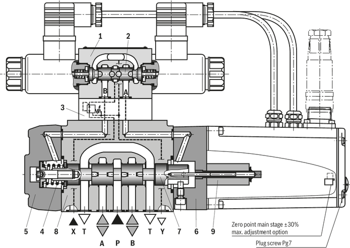
The 2nd stage is basically set-up of modules of our proportional valves. The zero point adjustment at "zero point main stage" is made at the factory and can be adjusted in a range of ± 30% of the nominal stroke via a potentiometer in the control electronics. Access in the integrated control electronics by removing a plug screw on the front side of the cover housing. When the pilot control valve or the control electronics are exchanged, they are to be re-adjusted. All adjustments may be implemented by instructed experts only.
Changes in the zero point may result in damage to the system and may only be implemented by instructed specialists!
The pilot control valve is a direct operated proportional valve. The control edge geometry has been optimized for the use as pilot control valve for proportional directional valves type 4WRKE. The proportional solenoids are pressure-tight, wet-pin DC solenoids with detachable coils. They convert the electric current proportionally into mechanical force. An increase of the current results in a correspondingly higher solenoid force. The set solenoid force will remain constant over the entire control stroke.
The pilot control valve mainly consists of the housing (1), the proportional solenoid (2 and 3), the valve control spool (4) and springs (5 and 6). In non-actuated state both actuators are connected to the tank. If one of the two solenoids (2 or 3) is excited, the magnetic force will move the valve control spool (4) towards the spring (5 or 6). After having overcome the overlap area, the connection of one of the two actuators to the tank is blocked and the connection to the pressure chamber is made. There is a flow from P to the control chamber of the main stage.
Valves of type 4WRKE are 2-stage proportional directional valves. They control the flow direction and size. The main stage is position-controlled so that the control spool position is independent from flow forces also in the case of bigger flows.
The valves mainly consist of the pilot control valve (1), the housing (8), the main control spool (7), the covers (5 and 6), the centering spring (4), the inductive position transducer (9) and the pressure reducing valve (3). If there is no input signal, the main control spool (7) will be kept in the central position by the centering spring (4). Both control chambers in the covers (5 and 6) are connected to the tank via the valve control spool (2). The main control spool (7) is connected to suited control electronics via the inductive position transducer (9). Both the position change of the main control spool (7) and the change of the command value at the junction summing of the amplifier create a voltage difference. During the comparison of command value and actual value, a possible control deviation is determined via the electronics and the proportional solenoid of the pilot control valve (1) is supplied with current. The current induces a force in the solenoid which operates the control spool via a plunger in a row. The flow which is activated via the control cross-sections leads to an adjustment of the main control spool. The main control spool (7) with the core of the inductive position transducer (9) attached to it is displaced until the actual value corresponds to the command value. In controlled state, the main control spool (7) is force-balanced and kept in this controlled position. The control spool stroke and the control opening change proportionally to the command value. The control electronics is integrated in the valve. By adjusting valve and electronics, the deviation in series production of the devices is kept low.
The tank lines must not be allowed to run empty; with corresponding installation conditions, a preload valve (preload pressure approx. 2 bar) must be installed.
The 2nd stage is basically set-up of modules of our proportional valves. The zero point adjustment at "zero point main stage" is made at the factory and can be adjusted in a range of ± 30% of the nominal stroke via a potentiometer in the control electronics. Access in the integrated control electronics by removing a plug screw on the front side of the cover housing. When the pilot control valve or the control electronics are exchanged, they are to be re-adjusted. All adjustments may be implemented by instructed experts only.
Changes in the zero point may result in damage to the system and may only be implemented by instructed specialists!
01 | 02 | 03 | 04 | 05 | 06 | 07 | 08 | 09 | 10 | 11 | 12 | 13 | 14 | 15 | 16 | ||
4 | WRZ | ‒ | 7X | / | 6E | G24 | * |
01 | 4 main ports | 4 |
02 | Proportional directional valve with electro-hydraulic operation and external electronics | WRZ |
03 | Size 10 | 10 |
Size 16 | 16 | |
Size 25 | 25 | |
Size 32 | 32 | |
Size 52 | 52 | |
04 | Symbols; for the possible version, see "Symbols/Circuit diagrams" | E; E1-; E3-; W6-; W8-; W9-; EA; W6A |
Rated flow NG10 | ||
05 | 25 l/min | 25 |
50 l/min | 50 | |
90 l/min | 85 | |
Rated flow NG16 | ||
05 | 100 l/min | 100 |
125 l/min | 125 | |
150 l/min | 150 | |
180 l/min | 180 | |
Rated flow NG25 | ||
05 | 220 l/min | 220 |
325 l/min | 325 | |
Rated flow NG32 | ||
05 | 360 l/min | 360 |
520 l/min | 520 | |
Rated flow NG52 | ||
05 | 1000 l/min | 1000 |
06 | Component series 70 ... 79 (70 ... 79: unchanged installation and connection dimensions) | 7X |
07 | For subplate mounting | no code |
For flange connection (only NG 52) | F | |
08 | Pilot control valve NG6 | 6E |
09 | Supply voltage 24 V | G24 |
10 | Without manual override | no code |
With concealed manual override | N9 1) | |
11 | Without special type of protection | no code |
Sea water-resistant | J 2) | |
Pilot oil supply and return | ||
12 | External pilot oil supply, external pilot oil return | no code |
Internal pilot oil supply, external pilot oil return | E | |
Pilot oil supply internal, pilot oil return internal | ET | |
External pilot oil supply, internal pilot oil return | T | |
Electrical connection | ||
13 | Without mating connector, with connector according to DIN EN 175301-803, separate order | K43) |
Without mating connector, connector according to DIN EN 175201-804 | K31 3) | |
14 | Without pressure reducing valve | no code |
With pressure reducing valve ZDR 6 DP0-4X/40YM-W80 (fixedly set) | D3 | |
15 | NBR seals | M |
FKM seals | V | |
16 | Further details in the plain text | * |
1) | With version “J” → “N” instead of “N9” | |
2) | For data regarding the seawater-resistant version refer to data sheet 29115-M | |
3) | For version "J" = seawater-resistant only "K31" | |
Type | 4WRKE | ||||||
Size | 10 | 16 | 25 | 27 | 32 | 35 | |
Installation position | any, preferably horizontal | ||||||
Ambient temperature range | °C | -20 … +50 | |||||
Storage temperature range | °C | -20 … +80 | |||||
Weight | kg | 8.7 | 11.2 | 16.8 | 17 | 31.5 | 34 |
Sine test according to DIN EN 60068-2-6 | 10 cycles, 10…2000.. 10 Hz with logarithmic frequency changing speed of 1 octave/min, 5 to 57 Hz, amplitude 1.5 mm (p-p), 57 to 2000 Hz, amplitude 10g, 3 axes | ||||||
Noise test according to DIN EN 60068-2-64 | 20…2000 Hz, amplitude 0.05g2/Hz (10gRMS) 3 axes, testing time 30 min per axis | ||||||
Shock test according to DIN EN 60068-2-27 | Half-sine 15g / 11 ms, 3 times in positive and 3 times in negative direction per axis, 3 axes | ||||||
Damp heat according to DIN EN 60068-2-30 | Variant 2: +25 °C … +55 °C, 90 % … 97 % relative humidity, 2 cycles á 24 hours | ||||||
Size | 10 | 16 | 25 | 27 | 32 | 35 | |||
Maximum operating pressure | bar | 350 | |||||||
Maximum operating pressure | Port P | bar | 315 | 350 | 210 | 350 | |||
Anschluss A | bar | 315 | 350 | 210 | 350 | ||||
Port B | bar | 315 | 350 | 210 | 350 | ||||
Operating pressure range | Pilot control valve, pilot oil supply | bar | 25 … 315 | ||||||
Maximum return flow pressure | Port T, external pilot oil return | bar | 315 | 250 | 210 | 250 | |||
Port T, internal pilot oil return | bar | 10 | |||||||
Port Y | bar | 10 | |||||||
Maximum flow | l/min | 170 | 460 | 870 | 1000 | 1600 | 3000 | ||
Nominal flow 1) | l/min | 25 50 100 | 125 150 200 220 | 220 350 | 500 | 400 600 | 1000 | ||
Pilot flow | input signal 0 → 100% | Port X and Y | l/min | 4.1 | 8.5 | 11.7 | 13 | ||
Hydraulic fluid temperature range | °C | -20 … +80 | |||||||
preferably | °C | -40 … +50 | |||||||
Viscosity range | mm²/s | 20 … 380 | |||||||
preferably | mm²/s | 30 … 45 | |||||||
Maximum admissible degree of contamination of the hydraulic fluid, cleanliness class according to ISO 4406 (c) 2) | Pilot control valve | Class 18/16/13 according to ISO 4406 (c) | |||||||
Main valve | Class 20/18/15 according to ISO 4406 (c) | ||||||||
Hysteresis | % | ≤ 1 | |||||||
Response sensitivity | % | ≤ 0.5 | |||||||
| 1) | ±10% with Δp = 10 bar, Δp = valve pressure differential |
| 2) | The cleanliness classes specified for the components must be adhered to in hydraulic systems. Effective filtration prevents faults and simultaneously increases the life cycle of the components. For the selection of the filters, see www.boschrexroth.com/filter. |
Size | 10 | 16 | 25 | 27 | 32 | 35 | ||
Voltage type | Direct voltage | |||||||
Type of signal | analog | |||||||
Maximum current consumption | of the amplifier | A | 1.5 | |||||
of the amplifier (impulse current) | A | 3 | ||||||
Protection class according to DIN EN 60529 | IP65 (If a suitable and a correctly mounted mating connector are used.) | |||||||
Power supply | V | 24 | ||||||
Supply voltage range | V | 18 … 35 | ||||||
Earthing (GND) | V | 0 | ||||||
Command value input | "A1" | V | 10 | |||||
Command value input range | "F1" | mA | 4 … 20 | |||||
Actual value output | "A1" | V | 10 | |||||
Actual value output range | "F1" | mA | 4 … 20 | |||||
Hydraulic fluid | Classification | Suitable sealing materials | Standards |
Mineral oils and related hydrocarbons | HL, HLP | NBR / FKM | DIN 51524 |
Flame-resistant - containing water | HFC (Fuchs HYDROTHERM 46M, Petrofer Ultra Safe 620) | NBR | ISO 12922 |
Phosphoric acid esters | HFD-R | FKM | |
Important information on hydraulic fluids: For more information and data on the use of other hydraulic fluids please contact us. There may be limitations regarding the technical valve data (temperature, pressure range, life cycle, maintenance intervals, etc.). The flash point of the process and operating medium used must be 40 K over the maximum solenoid surface temperature. Flame-resistant - containing water: | |||
Characteristic curve L

Characteristic curve P

Size 10

Size 10

Size 16

Size 16

Size 25, Size 27

Size 25, Size 27

Size 32

Size 32

Size 35

Size 35

Characteristic curve L
Characteristic curve P
Size 10
Size 10
Size 16
Size 16
Size 25, Size 27
Size 25, Size 27
Size 32
Size 32
Size 35
Size 35


