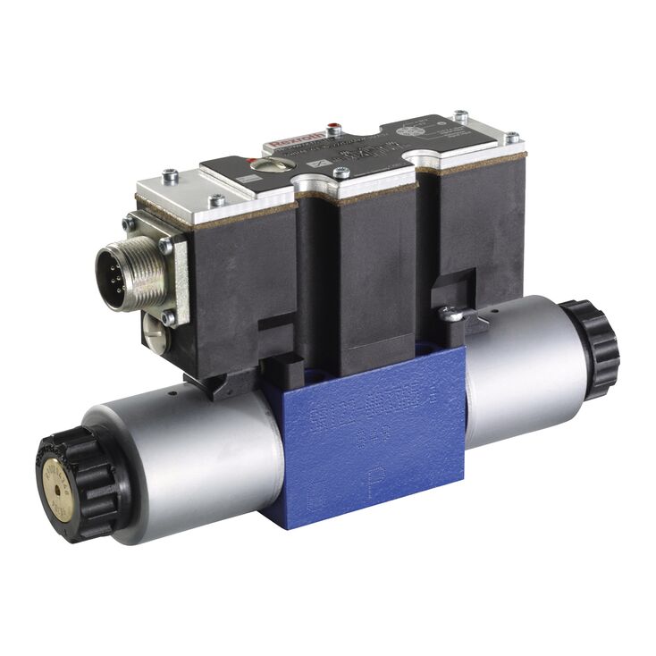
4WRAE 10 W1-30-2X/G24K31/F1V
Rexroth
R900707215
直动式比例换向阀,不带电气位置反馈,带集成电子装置(OBE)。
控制液流的方向与大小。
由带中心螺纹及可拆卸线圈的比例电磁铁驱动。
用于底板安装,油口布置符合ISO 4401。
弹簧对中的控制阀芯。
二位四通及三位四通比例换向阀为板式直动结构,由带中心螺纹、可拆卸线圈的比例电磁铁驱动,电磁铁通过集成电子装置控制。
该阀主要组成如下:
带连接面的阀体(1)
带压缩弹簧(3 和 4)的控制阀芯(2)
带中心螺纹的电磁铁(5 和 6)
集成电子装置(7)
电磁铁(5、6)断电时,压缩弹簧(3、4)使控制阀芯(2)保持中位。
通过给一个比例电磁铁通电来直接驱动控制阀芯(2),例如给电磁铁“b”(6)通电
控制阀芯(2)按电输入信号成比例地向左移动
P 至 A、B 至 T 通过具有渐进流量特性的节流截面连通
电磁铁(6)断电
控制阀芯(2)在压缩弹簧(3)的作用下返回中位
该版本功能与三阀位版本基本相同,但二阀位版本仅配电磁铁“a”。第二个比例电磁铁的位置在NG6中采用螺塞(8.1),在NG10中采用盖板(8.2)。
不得使回油管路排空;相应安装条件下必须安装预紧阀,预紧压力约2 bar。
01 | 02 | 03 | 04 | 05 | 06 | 07 | 08 | 09 | 10 | 11 | 12 | |||
4 | WRAE | ‒ | 2X | / | G24 | / | * |
01 | 4 main ports | 4 |
02 | Proportional directional valve with integrated electronics | WRAE |
03 | Size 6 | 6 |
Size 10 | 10 | |
04 | Symbols; for the possible version, see "Symbols/Circuit diagrams" | E; E1-; W; W1-; EA; WA |
Rated flow NG6 | ||
05 | 7 l/min | 7 |
15 l/min | 15 | |
30 l/min | 30 | |
Rated flow NG10 | ||
05 | 30 l/min | 30 |
60 l/min | 60 | |
06 | Component series 20 ... 29 (20 ... 29: unchanged installation and connection dimensions) | 2X |
07 | Supply voltage 24 V | G24 |
Special type of protection | ||
08 | Without special type of protection | no code |
Sea water-resistant | J 1) | |
Electrical connection | ||
09 | Connector DIN EN 175201-804 | K31 2) |
Electrical interface | ||
10 | Command value ±10 V | A1 |
Command value 4 to 20 mA | F1 | |
Seal material | ||
11 | NBR seals | M |
FKM seals | V | |
12 | Further details in the plain text | * |
1) | Electrical protection classes on request | |
2) | Only with NG6: only indicate "K31" for version “J”! | |
Type | 4WRAE | ||
Size | 6 | 10 | |
Installation position | any, preferably horizontal | ||
Ambient temperature range | °C | -20 … +50 | |
Storage temperature range | °C | -20 … +80 | |
Weight | kg | 2.2 | 6.8 |
Size | 6 | 10 | ||
Maximum operating pressure | bar | 315 | ||
Maximum operating pressure | Port P | bar | 315 | |
Port T | bar | 210 | ||
Anschluss A | bar | 315 | ||
Port B | bar | 315 | ||
Maximum flow | l/min | 42 | 75 | |
with double flow | l/min | 80 | 140 | |
Nominal flow | l/min | 7 15 26 | 30 60 | |
Hydraulic fluid 1) | Mineral oil (HL, HLP) to DIN 51524 | |||
Hydraulic fluid temperature range | °C | -20 … +80 | ||
preferably | °C | +40 … +50 | ||
Viscosity range | mm²/s | 20 … 380 | ||
preferably | mm²/s | 30 … 46 | ||
Maximum admissible degree of contamination of the hydraulic fluid, cleanliness class according to ISO 4406 (c) 2) | Class 20/18/15 according to ISO 4406 (c) | |||
Hysteresis | % | ≤ 5 | ||
Range of inversion | % | ≤ 1 | ||
Response sensitivity | % | ≤ 0.5 | ||
| 1) | Additional hydraulic fluids upon request |
| 2) | The cleanliness classes specified for the components must be adhered to in hydraulic systems. Effective filtration prevents faults and simultaneously increases the life cycle of the components. For the selection of the filters, see www.boschrexroth.com/filter. |
Hydraulic fluid | Classification | Suitable sealing materials | Standards |
Mineral oils and related hydrocarbons | HL, HLP | NBR / FKM | DIN 51524 |
Important information on hydraulic fluids: For more information and data on the use of other hydraulic fluids please contact us. | |||
Size | 6 | 10 | ||
Voltage type | Direct voltage | |||
Maximum solenoid current | A | 2.5 | ||
Maximum current consumption | of the amplifier | A | 1.8 | |
of the amplifier (impulse current) | A | 3 | ||
Solenoid coil resistance | Cold value at 20 °C | Ω | 2 | |
Maximum hot value | Ω | 3 | ||
Actuated time | % | 100 | ||
Maximum coil temperature 1) | °C | + 150 | ||
Power supply | VDC | 24 | ||
Supply voltage range | V | 19 … 35 | ||
Command value input | "A1" | V | ± 10 | |
Command value input range | "F1" | mA | 4 … 20 | |
| 1) | Due to the surface temperatures occurring at the solenoid coils, the European standards ISO 13732-1 and EN 982 need to be adhered to. |
NG6
NG6
NG6
NG6
NG6
NG6
NG6
NG10
NG10
NG10
NG10
NG10