| Availability: | |
|---|---|
| Quantity: | |

4WRAE 10 W1-30-2X/G24K31/F1V
Rexroth
R900707215
Direct operated proportional directional valve, without electrical position feedback, with integrated electronics (OBE)
Control of the direction and magnitude of a flow
Operation by means of proportional solenoids with central thread and detachable coil
For subplate mounting: Porting pattern according to ISO 4401
Spring-centered control spool
The 4/2 and 4/3 proportional directional valves are designed as direct operated devices in plate design. Operation by means of proportional solenoids with central thread and detachable coil. The solenoids are controlled via integrated electronics.
The valve basically consists of:
Housing (1) with connection surface
Control spool (2) with compression springs (3 and 4)
Solenoids (5 and 6) with central thread
Integrated electronics (7)
With de-energized solenoids (5 and 6), central position of the control spool (2) due to compression springs (3 and 4)
Direct actuation of the control spool (2) by energization of one proportional solenoid, e. g. energization of solenoid "b" (6)
Control spool (2) is moved to the left in proportion to the electrical input signal
Connection from P to A and B to T via orifice-type cross-sections with progressive flow characteristics
Switching off of the solenoid (6)
Control spool (2) is returned to the central position by the compression spring (3)

The function of this valve version basically corresponds to the valve with three spool positions. This 2 spool position valve is, however, only equipped with solenoid “a”. Instead of the 2nd proportional solenoid, there is a plug screw (8.1) with NG 6 or a cover (8.2) with NG10.
The tank line must not be allowed to run empty. With corresponding installation conditions, a preload valve (preload pressure approx. 2 bar) must be installed.
The 4/2 and 4/3 proportional directional valves are designed as direct operated devices in plate design. Operation by means of proportional solenoids with central thread and detachable coil. The solenoids are controlled via integrated electronics.
The valve basically consists of:
Housing (1) with connection surface
Control spool (2) with compression springs (3 and 4)
Solenoids (5 and 6) with central thread
Integrated electronics (7)
With de-energized solenoids (5 and 6), central position of the control spool (2) due to compression springs (3 and 4)
Direct actuation of the control spool (2) by energization of one proportional solenoid, e. g. energization of solenoid "b" (6)
Control spool (2) is moved to the left in proportion to the electrical input signal
Connection from P to A and B to T via orifice-type cross-sections with progressive flow characteristics
Switching off of the solenoid (6)
Control spool (2) is returned to the central position by the compression spring (3)
The function of this valve version basically corresponds to the valve with three spool positions. This 2 spool position valve is, however, only equipped with solenoid “a”. Instead of the 2nd proportional solenoid, there is a plug screw (8.1) with NG 6 or a cover (8.2) with NG10.
The tank line must not be allowed to run empty. With corresponding installation conditions, a preload valve (preload pressure approx. 2 bar) must be installed.
01 | 02 | 03 | 04 | 05 | 06 | 07 | 08 | 09 | 10 | 11 | 12 | |||
4 | WRAE | ‒ | 2X | / | G24 | / | * |
01 | 4 main ports | 4 |
02 | Proportional directional valve with integrated electronics | WRAE |
03 | Size 6 | 6 |
Size 10 | 10 | |
04 | Symbols; for the possible version, see "Symbols/Circuit diagrams" | E; E1-; W; W1-; EA; WA |
Rated flow NG6 | ||
05 | 7 l/min | 7 |
15 l/min | 15 | |
30 l/min | 30 | |
Rated flow NG10 | ||
05 | 30 l/min | 30 |
60 l/min | 60 | |
06 | Component series 20 ... 29 (20 ... 29: unchanged installation and connection dimensions) | 2X |
07 | Supply voltage 24 V | G24 |
Special type of protection | ||
08 | Without special type of protection | no code |
Sea water-resistant | J 1) | |
Electrical connection | ||
09 | Connector DIN EN 175201-804 | K31 2) |
Electrical interface | ||
10 | Command value ±10 V | A1 |
Command value 4 to 20 mA | F1 | |
Seal material | ||
11 | NBR seals | M |
FKM seals | V | |
12 | Further details in the plain text | * |
1) | Electrical protection classes on request | |
2) | Only with NG6: only indicate "K31" for version “J”! | |
Type | 4WRAE | ||
Size | 6 | 10 | |
Installation position | any, preferably horizontal | ||
Ambient temperature range | °C | -20 … +50 | |
Storage temperature range | °C | -20 … +80 | |
Weight | kg | 2.2 | 6.8 |
Size | 6 | 10 | ||
Maximum operating pressure | bar | 315 | ||
Maximum operating pressure | Port P | bar | 315 | |
Port T | bar | 210 | ||
Anschluss A | bar | 315 | ||
Port B | bar | 315 | ||
Maximum flow | l/min | 42 | 75 | |
with double flow | l/min | 80 | 140 | |
Nominal flow | l/min | 7 15 26 | 30 60 | |
Hydraulic fluid 1) | Mineral oil (HL, HLP) to DIN 51524 | |||
Hydraulic fluid temperature range | °C | -20 … +80 | ||
preferably | °C | +40 … +50 | ||
Viscosity range | mm²/s | 20 … 380 | ||
preferably | mm²/s | 30 … 46 | ||
Maximum admissible degree of contamination of the hydraulic fluid, cleanliness class according to ISO 4406 (c) 2) | Class 20/18/15 according to ISO 4406 (c) | |||
Hysteresis | % | ≤ 5 | ||
Range of inversion | % | ≤ 1 | ||
Response sensitivity | % | ≤ 0.5 | ||
| 1) | Additional hydraulic fluids upon request |
| 2) | The cleanliness classes specified for the components must be adhered to in hydraulic systems. Effective filtration prevents faults and simultaneously increases the life cycle of the components. For the selection of the filters, see www.boschrexroth.com/filter. |
Hydraulic fluid | Classification | Suitable sealing materials | Standards |
Mineral oils and related hydrocarbons | HL, HLP | NBR / FKM | DIN 51524 |
Important information on hydraulic fluids: For more information and data on the use of other hydraulic fluids please contact us. | |||
Size | 6 | 10 | ||
Voltage type | Direct voltage | |||
Maximum solenoid current | A | 2.5 | ||
Maximum current consumption | of the amplifier | A | 1.8 | |
of the amplifier (impulse current) | A | 3 | ||
Solenoid coil resistance | Cold value at 20 °C | Ω | 2 | |
Maximum hot value | Ω | 3 | ||
Actuated time | % | 100 | ||
Maximum coil temperature 1) | °C | + 150 | ||
Power supply | VDC | 24 | ||
Supply voltage range | V | 19 … 35 | ||
Command value input | "A1" | V | ± 10 | |
Command value input range | "F1" | mA | 4 … 20 | |
| 1) | Due to the surface temperatures occurring at the solenoid coils, the European standards ISO 13732-1 and EN 982 need to be adhered to. |
NG6
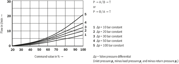
NG6
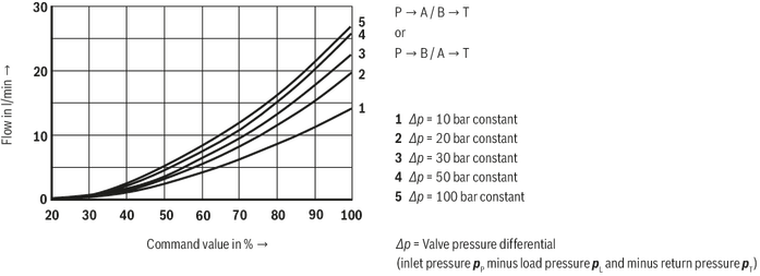
NG6
NG6
NG6
NG6
NG6
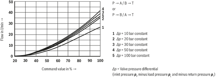
NG10
NG10
NG10
NG10
NG10
NG6
NG6
NG6
NG6
NG6
NG6
NG6
NG10
NG10
NG10
NG10
NG10


