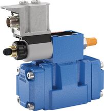
3DREME16P-7X/200YG24K31F1V
Rexroth
R901218100
三通型式。
由线圈可旋转的比例电磁铁驱动。
用于底板安装。
油口布置符合ISO 4401。
可选最高压力限制。
阀与控制电子装置由同一来源提供。
集成电子装置(OBE)使指令值—压力特性曲线的制造偏差较小。
线性的指令值—压力特性曲线。
3DRE(M)E型阀是电控先导式三通减压阀,带执行器压力限制。
用于系统压力的减压(P至A)及限制(A至T)。
结构
该阀由两个主要组件组成:
先导控制阀(1)带比例电磁铁(2)和集成电子装置 OBE(17),可选配最大压力限制装置(15)。供电电压和指令值电压接至连接器(16)。指令值与压力的特性曲线在出厂时已进行小制造公差校准。
主阀(3),带主阀芯(4)
功能
通过先导控制阀(1),按指令值设置 A 口所需的减压压力。
P口无压时,弹簧(5、6)使主阀芯(4)保持中位,防止执行器产生启动阶跃。
先导油从孔(7)经流量控制器(8)、控制腔(11)流至节流间隙(9),再经管路(10)流向 Y 口。该连接必须无压通向油箱。
减压
控制腔(11)中的先导压力随指令值建立。
通过喷嘴(12)在弹簧腔(13)内建立压力,使主阀芯(4)向右移动。液压油由 P 流向 A。
A口执行器压力作用于弹簧腔(14)。
当 A 口压力升至先导控制阀(1)的设定压力时,主阀芯(4)向左移动。A 口压力几乎等于先导控制阀(1)的设定压力。
压力限制
若 A 口压力超过先导控制阀(1)的设定压力,主阀芯(4)将进一步向左移动。
由此接通A至T,将A口压力限制在设定指令值。
3DREME型。
若比例电磁铁的电控电流过高,A 口压力必然升高。为防止这种不允许的液压超压情况,可选装弹簧加载的溢流阀作为最大压力限制装置(15)。最大压力限制已按相应压力等级预设,参见“技术参数”。
1 | Plug screw M6 according to DIN 906, wrench size 3 - Pilot oil return |
2 | Main valve |
3 | Cover |
Pilot oil supply | Pilot oil return | |
External | 1 closed | External |
Internal | 1 open | |
“XY”版本。
先导油由独立先导回路从外部供给,并通过Y口外部回油至油箱。
“Y”版本。
先导油由主阀P通道内部供给,通过Y口外部回油至油箱,底板中的X口封闭。
01 | 02 | 03 | 04 | 05 | 06 | 07 | 08 | 09 | 10 | 11 | 12 | 13 | ||
3DRE | E | P | - | 7X | / | G24 | K31 | * |
01 | Proportional pressure reducing valve in 3-way version, pilot-operated | 3DRE |
02 | Without maximum pressure limitation | no code |
With maximum pressure limitation | M | |
03 | With integrated electronics (OBE) | E |
04 | Size 10 | 10 |
Size 16 | 16 | |
05 | Subplate mounting | P |
06 | Component series 70 … 79 (70 … 79: unchanged installation and mounting dimensions) | 7X |
Pressure rating | ||
07 | Up to 50 bar | 50 |
Up to 100 bar | 100 | |
Up to 200 bar | 200 | |
Up to 250 bar (NG16 only) | 250 | |
Up to 315 bar (NG10 only) | 315 | |
08 | Internal pilot oil supply, external pilot oil return | Y |
External pilot oil supply, external pilot oil return | XY | |
Power supply | ||
09 | Direct voltage 24 V | G24 |
Electrical connection | ||
10 | Without mating connector; connector DIN EN 175201-804 | K31 |
Interfaces of the control electronics | ||
11 | Command value input 0 ... +10 V | A1 |
Command value input 4 ... 20 mA | F1 | |
Seal material (observe compatibility of seals with hydraulic fluid used, see "Technical data") | ||
12 | NBR seals | M |
FKM seals | V | |
13 | Further details in the plain text | * |
Type | 3DRE(M)E | ||
Size | 10 | 16 | |
Installation position | any, preferably horizontal | ||
Weight | kg | 7.6 | 10.4 |
Storage temperature range | °C | -20 … +80 | |
Ambient temperature range | °C | -20 … +50 | |
Type | 3DRE(M)E | |||
Size | 10 | 16 | ||
Maximum operating pressure | Port P | bar | 350 | 315 |
Anschluss A | bar | 315 | 250 | |
Port T | bar | 315 | 250 | |
Port X | bar | 350 | 315 | |
Port Y | separate and depressurized to the tank | |||
Maximum set pressure in port A | Pressure rating 50 bar | bar | 50 | |
Pressure rating 100 bar | bar | 100 | ||
Pressure rating 200 bar | bar | 200 | ||
Pressure rating 250 bar | bar | - | 250 | |
Pressure rating 315 bar | bar | 315 | - | |
Minimum set pressure 1) | bar | < 5 | < 4 | |
Maximum pressure limitation 2) | Pressure rating 50 bar | bar | 70 | |
Pressure rating 100 bar | bar | 130 | ||
Pressure rating 200 bar | bar | 230 | ||
Pressure rating 250 bar | bar | - | 270 | |
Pressure rating 315 bar | bar | 350 | - | |
Maximum flow | l/min | 125 | 300 | |
Pilot flow | l/min | 1.1 | ||
Hydraulic fluid | see table "Hydraulic fluid" | |||
Hydraulic fluid temperature range | °C | -20 … +80 | ||
Viscosity range | mm²/s | 15 … 380 | ||
Maximum admissible degree of contamination of the hydraulic fluid, cleanliness class according to ISO 4406 (c) 3) | Class 20/18/15 | |||
Hysteresis 4) | % | ± 3 | ||
Repetition accuracy 4) | % | < ± 2 | ||
Linearity 4) | % | ± 3.5 | ||
Manufacturing tolerance of the command value pressure characteristic curve 5) | at command value 20 % | % | < ± 1.5 | |
at command value 100 % | % | < ± 1.5 | ||
Step response Tu + Tg 6) | 10 ... 90% | ms | < 140 | |
| 1) | In channel A without flow, with command value 0 (see characteristic curves) |
| 2) | Continuously adjustable, set at the factory |
| 3) | The cleanliness classes specified for the components must be adhered to in hydraulic systems. Effective filtration prevents faults and simultaneously increases the life cycle of the components. For the selection of the filters, see www.boschrexroth.com/filter. |
| 4) | Of the maximum set pressure |
| 5) | Of the maximum set pressure; related to the hysteresis characteristic curve; pressure increasing; zero point calibration at the factory |
| 6) | Measured with standing hydraulic fluid column, 1.0 L at port A |
Hydraulic fluid | Classification | Suitable sealing materials | Standards | Data sheet | |
Mineral oils | HL, HLP, HLPD, HVLP, HVLPD | NBR, FKM | DIN 51524 | 90220 | |
Bio-degradable | Insoluble in water | HETG | NBR, FKM | ISO 15380 | 90221 |
HEES | FKM | ||||
Soluble in water | HEPG | FKM | ISO 15380 | ||
Flame-resistant | Water-free | HFDU (glycol base) | FKM | ISO 12922 | 90222 |
HFDU (ester base) | FKM | ||||
HFDR | FKM | ||||
Containing water | HFC (Fuchs: Hydrotherm 46M, Renosafe 500; | NBR | ISO 12922 | 90223 | |
Important information on hydraulic fluids:
| |||||
Type | 3DRE(M)E | ||
Power supply | Nominal voltage | VDC | 24 |
Lower limit value | VDC | 21 | |
Upper limit value | VDC | 35 | |
Current consumption | A | ≤ 1.5 | |
Required fuse protection | 2, time-lag | ||
Inputs | Voltage | V | 0 … 10 |
Current | mA | 4 … 20 | |
Outlet | Actual current value | 1 mV ≙ 1 mA | |
Protection class according to EN 60529 | IP65 (with correctly installed electrical connection) | ||
压力等级 50 bar
压力等级 100 bar
压力等级 200 bar
压力等级 315 bar
注意:
阀体与液压油的温度已达到平衡;较大的温差可能导致数值发生偏差。
压力等级 50 bar
压力等级 100 bar
压力等级 200 bar
压力等级 250 bar
注意:
阀体与液压油的温度已达到平衡;较大的温差可能导致数值发生偏差。