| Availability: | |
|---|---|
| Quantity: | |

3DREME16P-7X/200YG24K31F1V
Rexroth
R901218100
3-way version
Operation by means of proportional solenoid with rotatable coil
For subplate mounting
Porting pattern according to ISO 4401
Maximum pressure limitation, optional
Valve and control electronics from a single source
Integrated electronics (OBE) with little manufacturing tolerance of the command value pressure characteristic curve
Linear command value pressure characteristic curve
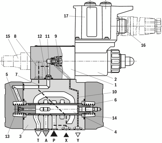
Valves of type 3DRE(M)E are electrically pilot-operated 3-way pressure reducing valves with pressure limitation of the actuator.
They are used for reduction (P to A) and limitation (A to T) of a system pressure.
Set-up
The valves consist of two main assemblies:
Pilot control valve (1) with proportional solenoid (2) and integrated electronics (OBE) (17), optionally with maximum pressure limitation (15). Supply and command value voltage are applied at the connector (16). At the factory, the command value pressure characteristic curve is adjusted with little manufacturing tolerance.
Main valve (3) with main control spool (4)
Function
Command value-dependent setting of the pressure to be reduced in port A via the pilot control valve (1).
With depressurized port P, the springs (5) and (6) hold the main control spool (4) in its central position. In this way, a start-up jump at the actuator is prevented.
Pilot fluid flows from bore (7) via the flow controller (8), via the control chamber (11) to the throttle gap (9), via line (10) to port Y. This connection is to be led into the tank at zero pressure.
Pressure reduction
Build-up of the pilot pressure in the control chamber (11) as function of the command value.
Pressure build-up in the spring chamber (13) via nozzle (12) and movement of the main control spool (4) to the right. Hydraulic fluid flows from P to A.
The actuator pressure in port A is available in the spring chamber (14).
Increase in the pressure in port A to the set pressure of the pilot control valve (1) leads to the movement of the main spool (4) to the left. Pressure in port A is almost identical with the set pressure at the pilot control valve (1).
Pressure limitation
If the pressure in port A exceeds the set pressure of the pilot control valve (1), the main control spool (4) is moved further to the left.
This opens the connection from A to T and limits the pressure pending in port A to the set command value.
Type 3DREME
For hydraulic protection against an inadmissibly high electric control current at the proportional solenoid, which imperatively results in increased pressures in port A, you can optionally install a spring-loaded pressure relief valve as maximum pressure limitation (15). The maximum pressure limitation is pre-set, referred to the relevant pressure rating (see "Technical data").


1 | Plug screw M6 according to DIN 906, wrench size 3 - Pilot oil return |
2 | Main valve |
3 | Cover |
Pilot oil supply | Pilot oil return | |
External | 1 closed | External |
Internal | 1 open | |
Version "XY"
The pilot oil is supplied externally from a separate pilot circuit. The pilot oil return is implemented externally via port Y into the tank.
Version "Y"
The pilot oil supply is implemented internally from channel P of the main valve. The pilot oil return is implemented externally via port Y into the tank. In the subplate, port X is closed.
Valves of type 3DRE(M)E are electrically pilot-operated 3-way pressure reducing valves with pressure limitation of the actuator.
They are used for reduction (P to A) and limitation (A to T) of a system pressure.
Set-up
The valves consist of two main assemblies:
Pilot control valve (1) with proportional solenoid (2) and integrated electronics (OBE) (17), optionally with maximum pressure limitation (15). Supply and command value voltage are applied at the connector (16). At the factory, the command value pressure characteristic curve is adjusted with little manufacturing tolerance.
Main valve (3) with main control spool (4)
Function
Command value-dependent setting of the pressure to be reduced in port A via the pilot control valve (1).
With depressurized port P, the springs (5) and (6) hold the main control spool (4) in its central position. In this way, a start-up jump at the actuator is prevented.
Pilot fluid flows from bore (7) via the flow controller (8), via the control chamber (11) to the throttle gap (9), via line (10) to port Y. This connection is to be led into the tank at zero pressure.
Pressure reduction
Build-up of the pilot pressure in the control chamber (11) as function of the command value.
Pressure build-up in the spring chamber (13) via nozzle (12) and movement of the main control spool (4) to the right. Hydraulic fluid flows from P to A.
The actuator pressure in port A is available in the spring chamber (14).
Increase in the pressure in port A to the set pressure of the pilot control valve (1) leads to the movement of the main spool (4) to the left. Pressure in port A is almost identical with the set pressure at the pilot control valve (1).
Pressure limitation
If the pressure in port A exceeds the set pressure of the pilot control valve (1), the main control spool (4) is moved further to the left.
This opens the connection from A to T and limits the pressure pending in port A to the set command value.
Type 3DREME
For hydraulic protection against an inadmissibly high electric control current at the proportional solenoid, which imperatively results in increased pressures in port A, you can optionally install a spring-loaded pressure relief valve as maximum pressure limitation (15). The maximum pressure limitation is pre-set, referred to the relevant pressure rating (see "Technical data").
1 | Plug screw M6 according to DIN 906, wrench size 3 - Pilot oil return |
2 | Main valve |
3 | Cover |
Pilot oil supply | Pilot oil return | |
External | 1 closed | External |
Internal | 1 open | |
Version "XY"
The pilot oil is supplied externally from a separate pilot circuit. The pilot oil return is implemented externally via port Y into the tank.
Version "Y"
The pilot oil supply is implemented internally from channel P of the main valve. The pilot oil return is implemented externally via port Y into the tank. In the subplate, port X is closed.
01 | 02 | 03 | 04 | 05 | 06 | 07 | 08 | 09 | 10 | 11 | 12 | 13 | ||
3DRE | E | P | - | 7X | / | G24 | K31 | * |
01 | Proportional pressure reducing valve in 3-way version, pilot-operated | 3DRE |
02 | Without maximum pressure limitation | no code |
With maximum pressure limitation | M | |
03 | With integrated electronics (OBE) | E |
04 | Size 10 | 10 |
Size 16 | 16 | |
05 | Subplate mounting | P |
06 | Component series 70 … 79 (70 … 79: unchanged installation and mounting dimensions) | 7X |
Pressure rating | ||
07 | Up to 50 bar | 50 |
Up to 100 bar | 100 | |
Up to 200 bar | 200 | |
Up to 250 bar (NG16 only) | 250 | |
Up to 315 bar (NG10 only) | 315 | |
08 | Internal pilot oil supply, external pilot oil return | Y |
External pilot oil supply, external pilot oil return | XY | |
Power supply | ||
09 | Direct voltage 24 V | G24 |
Electrical connection | ||
10 | Without mating connector; connector DIN EN 175201-804 | K31 |
Interfaces of the control electronics | ||
11 | Command value input 0 ... +10 V | A1 |
Command value input 4 ... 20 mA | F1 | |
Seal material (observe compatibility of seals with hydraulic fluid used, see "Technical data") | ||
12 | NBR seals | M |
FKM seals | V | |
13 | Further details in the plain text | * |
Type | 3DRE(M)E | ||
Size | 10 | 16 | |
Installation position | any, preferably horizontal | ||
Weight | kg | 7.6 | 10.4 |
Storage temperature range | °C | -20 … +80 | |
Ambient temperature range | °C | -20 … +50 | |
Type | 3DRE(M)E | |||
Size | 10 | 16 | ||
Maximum operating pressure | Port P | bar | 350 | 315 |
Anschluss A | bar | 315 | 250 | |
Port T | bar | 315 | 250 | |
Port X | bar | 350 | 315 | |
Port Y | separate and depressurized to the tank | |||
Maximum set pressure in port A | Pressure rating 50 bar | bar | 50 | |
Pressure rating 100 bar | bar | 100 | ||
Pressure rating 200 bar | bar | 200 | ||
Pressure rating 250 bar | bar | - | 250 | |
Pressure rating 315 bar | bar | 315 | - | |
Minimum set pressure 1) | bar | < 5 | < 4 | |
Maximum pressure limitation 2) | Pressure rating 50 bar | bar | 70 | |
Pressure rating 100 bar | bar | 130 | ||
Pressure rating 200 bar | bar | 230 | ||
Pressure rating 250 bar | bar | - | 270 | |
Pressure rating 315 bar | bar | 350 | - | |
Maximum flow | l/min | 125 | 300 | |
Pilot flow | l/min | 1.1 | ||
Hydraulic fluid | see table "Hydraulic fluid" | |||
Hydraulic fluid temperature range | °C | -20 … +80 | ||
Viscosity range | mm²/s | 15 … 380 | ||
Maximum admissible degree of contamination of the hydraulic fluid, cleanliness class according to ISO 4406 (c) 3) | Class 20/18/15 | |||
Hysteresis 4) | % | ± 3 | ||
Repetition accuracy 4) | % | < ± 2 | ||
Linearity 4) | % | ± 3.5 | ||
Manufacturing tolerance of the command value pressure characteristic curve 5) | at command value 20 % | % | < ± 1.5 | |
at command value 100 % | % | < ± 1.5 | ||
Step response Tu + Tg 6) | 10 ... 90% | ms | < 140 | |
| 1) | In channel A without flow, with command value 0 (see characteristic curves) |
| 2) | Continuously adjustable, set at the factory |
| 3) | The cleanliness classes specified for the components must be adhered to in hydraulic systems. Effective filtration prevents faults and simultaneously increases the life cycle of the components. For the selection of the filters, see www.boschrexroth.com/filter. |
| 4) | Of the maximum set pressure |
| 5) | Of the maximum set pressure; related to the hysteresis characteristic curve; pressure increasing; zero point calibration at the factory |
| 6) | Measured with standing hydraulic fluid column, 1.0 L at port A |
Hydraulic fluid | Classification | Suitable sealing materials | Standards | Data sheet | |
Mineral oils | HL, HLP, HLPD, HVLP, HVLPD | NBR, FKM | DIN 51524 | 90220 | |
Bio-degradable | Insoluble in water | HETG | NBR, FKM | ISO 15380 | 90221 |
HEES | FKM | ||||
Soluble in water | HEPG | FKM | ISO 15380 | ||
Flame-resistant | Water-free | HFDU (glycol base) | FKM | ISO 12922 | 90222 |
HFDU (ester base) | FKM | ||||
HFDR | FKM | ||||
Containing water | HFC (Fuchs: Hydrotherm 46M, Renosafe 500; | NBR | ISO 12922 | 90223 | |
Important information on hydraulic fluids:
| |||||
Type | 3DRE(M)E | ||
Power supply | Nominal voltage | VDC | 24 |
Lower limit value | VDC | 21 | |
Upper limit value | VDC | 35 | |
Current consumption | A | ≤ 1.5 | |
Required fuse protection | 2, time-lag | ||
Inputs | Voltage | V | 0 … 10 |
Current | mA | 4 … 20 | |
Outlet | Actual current value | 1 mV ≙ 1 mA | |
Protection class according to EN 60529 | IP65 (with correctly installed electrical connection) | ||
Type | 3DRE(M)E | ||
Size | 10 | 16 | |
Installation position | any, preferably horizontal | ||
Weight | kg | 7.6 | 10.4 |
Storage temperature range | °C | -20 … +80 | |
Ambient temperature range | °C | -20 … +50 | |
Type | 3DRE(M)E | |||
Size | 10 | 16 | ||
Maximum operating pressure | Port P | bar | 350 | 315 |
Anschluss A | bar | 315 | 250 | |
Port T | bar | 315 | 250 | |
Port X | bar | 350 | 315 | |
Port Y | separate and depressurized to the tank | |||
Maximum set pressure in port A | Pressure rating 50 bar | bar | 50 | |
Pressure rating 100 bar | bar | 100 | ||
Pressure rating 200 bar | bar | 200 | ||
Pressure rating 250 bar | bar | - | 250 | |
Pressure rating 315 bar | bar | 315 | - | |
Minimum set pressure 1) | bar | < 5 | < 4 | |
Maximum pressure limitation 2) | Pressure rating 50 bar | bar | 70 | |
Pressure rating 100 bar | bar | 130 | ||
Pressure rating 200 bar | bar | 230 | ||
Pressure rating 250 bar | bar | - | 270 | |
Pressure rating 315 bar | bar | 350 | - | |
Maximum flow | l/min | 125 | 300 | |
Pilot flow | l/min | 1.1 | ||
Hydraulic fluid | see table "Hydraulic fluid" | |||
Hydraulic fluid temperature range | °C | -20 … +80 | ||
Viscosity range | mm²/s | 15 … 380 | ||
Maximum admissible degree of contamination of the hydraulic fluid, cleanliness class according to ISO 4406 (c) 3) | Class 20/18/15 | |||
Hysteresis 4) | % | ± 3 | ||
Repetition accuracy 4) | % | < ± 2 | ||
Linearity 4) | % | ± 3.5 | ||
Manufacturing tolerance of the command value pressure characteristic curve 5) | at command value 20 % | % | < ± 1.5 | |
at command value 100 % | % | < ± 1.5 | ||
Step response Tu + Tg 6) | 10 ... 90% | ms | < 140 | |
| 1) | In channel A without flow, with command value 0 (see characteristic curves) |
| 2) | Continuously adjustable, set at the factory |
| 3) | The cleanliness classes specified for the components must be adhered to in hydraulic systems. Effective filtration prevents faults and simultaneously increases the life cycle of the components. For the selection of the filters, see www.boschrexroth.com/filter. |
| 4) | Of the maximum set pressure |
| 5) | Of the maximum set pressure; related to the hysteresis characteristic curve; pressure increasing; zero point calibration at the factory |
| 6) | Measured with standing hydraulic fluid column, 1.0 L at port A |
Hydraulic fluid | Classification | Suitable sealing materials | Standards | Data sheet | |
Mineral oils | HL, HLP, HLPD, HVLP, HVLPD | NBR, FKM | DIN 51524 | 90220 | |
Bio-degradable | Insoluble in water | HETG | NBR, FKM | ISO 15380 | 90221 |
HEES | FKM | ||||
Soluble in water | HEPG | FKM | ISO 15380 | ||
Flame-resistant | Water-free | HFDU (glycol base) | FKM | ISO 12922 | 90222 |
HFDU (ester base) | FKM | ||||
HFDR | FKM | ||||
Containing water | HFC (Fuchs: Hydrotherm 46M, Renosafe 500; | NBR | ISO 12922 | 90223 | |
Important information on hydraulic fluids:
| |||||
Type | 3DRE(M)E | ||
Power supply | Nominal voltage | VDC | 24 |
Lower limit value | VDC | 21 | |
Upper limit value | VDC | 35 | |
Current consumption | A | ≤ 1.5 | |
Required fuse protection | 2, time-lag | ||
Inputs | Voltage | V | 0 … 10 |
Current | mA | 4 … 20 | |
Outlet | Actual current value | 1 mV ≙ 1 mA | |
Protection class according to EN 60529 | IP65 (with correctly installed electrical connection) | ||
Pressure rating 50 bar

Pressure rating 100 bar

Pressure rating 200 bar

Pressure rating 315 bar


Notice:
Valve body and hydraulic fluid temperature-compensated; large temperature differences may lead to differing values.
Pressure rating 50 bar

Pressure rating 100 bar

Pressure rating 200 bar

Pressure rating 250 bar


Notice:
Valve body and hydraulic fluid temperature-compensated; large temperature differences may lead to differing values.
Pressure rating 50 bar
Pressure rating 100 bar
Pressure rating 200 bar
Pressure rating 315 bar
Notice:
Valve body and hydraulic fluid temperature-compensated; large temperature differences may lead to differing values.
Pressure rating 50 bar
Pressure rating 100 bar
Pressure rating 200 bar
Pressure rating 250 bar
Notice:
Valve body and hydraulic fluid temperature-compensated; large temperature differences may lead to differing values.


