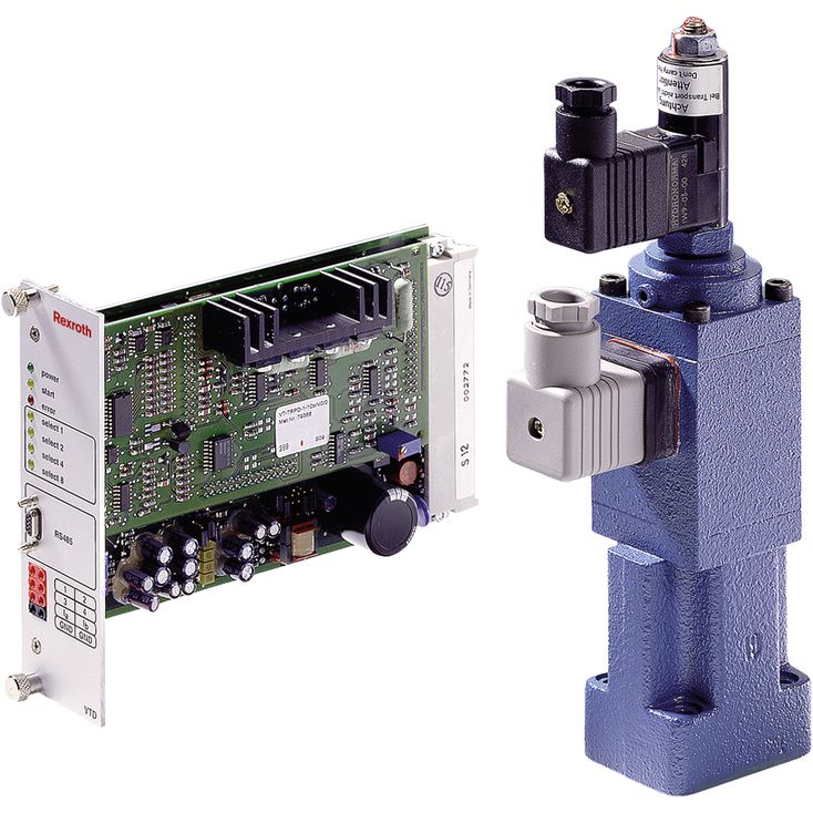
2FRE 6 A-2X/10QK4MV
Rexroth
R900937860
二通型式。
阀带压力补偿器,用于经压力补偿的流量控制。
由比例电磁铁控制。
用于底板安装,油口布置符合ISO 4401-03-02-0-05。
计量节流口带电气位置闭环控制。
位置传感器线圈可沿轴向移动,因此无需改动电液控制电子装置,即可方便地标定计量节流口的零点。
阀与可选的VT-VRPA1-150-1X模拟放大器及VT-MRPA1-150-1X模拟放大模块的制造偏差较小。
通过整流叠加板,实现双向流量控制。
01 | 02 | 03 | 04 | 05 | 06 | 07 | 08 | 09 | ||
2FRE | 6 | - | 2X | / | K4 | V | * |
01 | Proportional flow control valve in 2-way version | 2FRE | |
02 | Size 6 | 6 | |
03 | With external closing of the pressure compensator (suppression of the start-up jump) | A | |
Without external closing of the pressure compensator | B | ||
04 | Component series 20 ... 29 (20 ... 29: unchanged installation and connection dimensions) | 2X | |
rated flow A → B, flow characteristic | |||
05 | Linear | Up to 1 l/min | 1L |
Up to 2 l/min | 2L | ||
Up to 8 l/min | 8L | ||
Progressive | Up to 3 l/min | 3Q | |
Up to 6 l/min | 6Q | ||
Up to 10 l/min | 10Q | ||
Up to 16 l/min | 16Q | ||
Up to 25 l/min | 25Q | ||
Progressive with rapid traverse | Fine control range up to 2 l/min | 2QE | |
Electrical connection | |||
06 | Individual connection | ||
Without mating connector, connector DIN EN 175301-803-A (proportional solenoid) and GSA20 (position transducer) | K41) | ||
07 | With check valve | R | |
Without check valve | M | ||
Seal material | |||
08 | FKM seals | V | |
Observe compatibility of seals with hydraulic fluid used. (Other seals upon request) | |||
09 | Further details in the plain text | * | |
| 1) | Mating connectors, separate order, see "Accessories" and datasheet 08006. |
Size | 6 | |
Component series | 2X | |
Installation position | Any | |
Weight | kg | 1.8 |
Storage temperature range | °C | -20 … +80 |
Ambient temperature range | °C | -20 … +50 |
Size | 6 | ||
Maximum operating pressure | Anschluss A | bar | 210 |
Minimum pressure differential | bar | 6 … 10 | |
Pressure differential with free return flow B → A | See characteristic curve | ||
Pressure/flow-dependence of input/output pressure | See characteristic curve | ||
Temperature drift | See characteristic curve | ||
Hydraulic fluid | see table | ||
Hydraulic fluid temperature range | °C | -20 … +80 | |
Viscosity range | mm²/s | 15 … 380 | |
Maximum admissible degree of contamination of the hydraulic fluid, cleanliness class according to ISO 4406 (c) 1) | Class 20/18/15 according to ISO 4406 (c) | ||
Hysteresis | of qVmax | % | < ± 1 |
Repetition accuracy | of qVmax | % | < 1 |
Manufacturing tolerance | at command value 33 % | % | ≤ ± 3 |
at command value 100 % | % | ≤ ± 5 | |
| 1) | The cleanliness classes specified for the components must be adhered to in hydraulic systems. Effective filtration prevents faults and simultaneously increases the life cycle of the components. For the selection of the filters, see www.boschrexroth.com/filter. |
Version | 1L | 2L | 8L | 3Q | 6Q | 10Q | 16Q | 25Q | 2QE | ||
Maximum flow | l/min | 1 | 2 | 8 | 3 | 6 | 10 | 16 | 25 | ||
Minimum flow | 100 bar | ml/min | 25 | 50 | 15 | 25 | 50 | 70 | 100 | 15 | |
210 bar | ml/min | 25 | 50 | 25 | 50 | 70 | 100 | 25 | |||
Maximum leakage flow, Δp A → B with a command value of 0% 1) | 50 bar | ml/min | 4 | 6 | 4 | 6 | 7 | 10 | 4 | ||
100 bar | ml/min | 5 | 8 | 5 | 8 | 10 | 15 | 5 | |||
210 bar | ml/min | 7 | 12 | 7 | 12 | 15 | 22 | 7 | |||
| 1) | Measured with ν = 41 mm2/s and ϑ = 50 °C |
Hydraulic fluid | Classification | Suitable sealing materials | Standards | Data sheet |
Mineral oils | HL, HLP | FKM | DIN 51524 | 90220 |
Flame-resistant - water-free | HFDU (glycol base) | FKM | ISO 12922 | 90222 |
Important information on hydraulic fluids: For more information and data on the use of other hydraulic fluids please contact us. There may be limitations regarding the technical valve data (temperature, pressure range, life cycle, maintenance intervals, etc.). The ignition temperature of the hydraulic fluid used must be 50 K higher than the maximum surface temperature. | ||||
Voltage type | Direct voltage | ||
Maximum current per solenoid | A | 1.5 | |
Coil resistance | Cold value at 20 °C | Ω | 5.4 |
Maximum hot value | Ω | 8.2 | |
Duty cycle | % | 100 | |
Electrical connection 1) | Connector according to DIN EN 175301-803-A | ||
Protection class according to DIN EN 60529 2) | IP65 (If a suitable and a correctly mounted mating connector are used.) | ||
| 1) | Mating connector, separate order |
| 2) | Due to the arising surface temperatures of the solenoid coils, the standards ISO 13732-1 and ISO 4413 are to be observed. |
Coil resistance at 20°C | Total resistance between 1 and 2 | Ω | 31.5 |
Total resistance between 2 and PE | Ω | 45.5 | |
Total resistance between PE and 1 | Ω | 31.5 | |
Electrical connection 1) | Connector GSA20 | ||
Type of protection according to EN 60529 2) | IP65 (If a suitable and a correctly mounted mating connector are used.) | ||
Inductivity | mH | 6 ... 8 | |
Oscillator frequency | kHz | 2.5 | |
Electrical position measurement system | Differential throttle | ||
Nominal stroke | mm | 3.5 | |
| 1) | Mating connector, separate order |
| 2) | Due to the arising surface temperatures of the solenoid coils, the standards ISO 13732-1 and ISO 4413 are to be observed. |
Dimensions in mm
| |
Required surface quality of the valve contact surface |
1 | Valve housing |
2 | Proportional solenoid with inductive position transducer |
3.1 | Mating connector for proportional solenoid, separate order |
3.2 | Mating connector for position transducer, separate order |
4 | Space required to remove the mating connector |
5 | Name plate |
6.1 | Identical seal rings for ports A, B, P and blind counterbore |
7 | |
8 | Port B |
9 | Blind counterbore Ø 12.6 mm |
10 | Machined valve contact surface; Porting pattern according to ISO 4401-03-02-0-05 |
Notice:
The dimensions are nominal dimensions which are subject to tolerances.
Subplates (separate order) with porting pattern according to ISO 4401-03-02-0-05, see data sheet 45100.
4 hexagon socket head cap screws ISO 4762 - M5 x 30 - 10.9-flZn-240h-L
(friction coefficient 0.09 … 0.14 according to VDA 235-101)
Tightening torque MA = 7 Nm ± 10 %, material no. R913048086
or
4 hexagon socket head cap screws ISO 4762 - M5 x 30 - 10.9
(friction coefficient 0.08 … 0.16 according to VDI 2230 – black)
Tightening torque MA = 8.1 Nm ± 10 %, material no. 2910150205
Rectifier sandwich plate impossible in proportional flow control valve, version “A” (with external closing of the pressure compensator).
The dimensions are nominal dimensions which are subject to tolerances.
2FRE ... 型比例流量阀具备二通功能,可根据电气指令值控制流量,并进行压力和温度补偿。
该结构主要由阀体(1)、带感应式位置传感器的比例电磁铁(2)、计量节流口(3)、压力补偿器(4)以及可选单向阀(5)组成。
流量设定由指令值电位器的0至100%刻度确定。指令值经放大器及比例电磁铁调节计量节流口(3);感应式位置传感器测量其位置,位置闭环控制修正相对指令值的任何偏差。
压力补偿器(4)始终保持计量节流口(3)两端压降恒定,因此流量获得负载补偿。
优化的计量节流口设计使温度漂移较小。指令值为0%时节流口关闭;电源故障或感应式位置传感器断线时,节流口也会关闭。
可从 0% 指令值平稳启动。通过电气放大器中的两个斜坡环节,可延时打开和关闭计量节流口。
通过单向阀(5),可由B向A自由回流。在比例流量控制阀下方另装Z4S 6...型整流叠加板,可调节执行器的进油及回油流量。
该阀的功能与“B...RV”型阀基本相同。
为在计量节流口(3)已打开(指令值 > 0%)时抑制启动突跳,可经 P 口(6)关闭压力补偿器(4)。此时,取消 A 口与压力补偿器(4)之间的内部连接。通过外部 P 口(6),换向阀(8)上游的 P 口压力作用于压力补偿器(4),克服弹簧力(7)使其保持关闭。当换向阀(8)切换为 P 至 B 时,压力补偿器(4)由关闭位置进入调节位置,从而避免启动突跳。