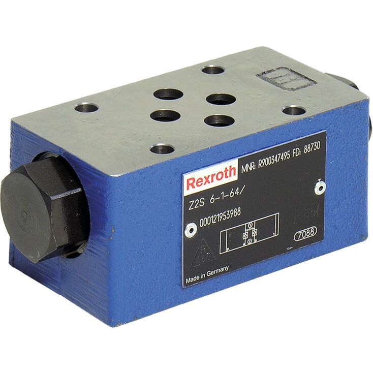
Z2S6-2-6X/
Rexroth
R900347496
用于垂直叠加安装的叠加板式阀。
油口布置符合DIN 24340 A型,不带定位孔。
油口布置符合ISO 4401-03-02-0-05,带定位孔。
可选对一个或两个执行器油口进行无泄漏封闭。
可选不同开启压力,参见订货代码。
可选预开启。
单向阀安装套件可单独提供。
可按需求提供特殊版本。
Z2S型截止阀是叠加板式液控单向阀。
用于对一个或两个执行器油口进行无泄漏截止,即使长时间停机也能保持截止。
从 A① 至 A② 或从 B① 至 B② 可自由流动,反方向则截止。
例如,当油流经阀由 A① 流向 A② 时,控制阀芯(1)向 B 侧移动,打开球座阀(2),随后将锥阀(3)推离阀座,使液压油能够从 B➁ 流向 B➀。
为确保球座阀(2)能够可靠关闭,控制阀芯(1)必须卸除液压力,参见回路示例。
预开启
通过预开启,可对受压油液进行阻尼卸压,从而避免可能的切换冲击。
具有较大控制开启比的两级结构,可在较低先导压力下可靠卸荷。
注意:
不带预开启功能的阀可能使封闭的受压容积突然卸压,由此产生的切换冲击可能造成所装元件过早磨损,并产生噪声。
1 | Control spool, area A2 |
2 | Poppet, area A1 |
3 | Stop |
1 | Control spool, area A2 |
2 | Poppet, area A1 |
3 | Stop |
4 | Control spool, area A4 |
5 | Pre-opening, area A3 |
1) Corrosion-resistant surface on request: e.g."J50" thick film passivated (DIN 50979 Fe//Zn8//Cn//T0)
2) Locking pin ISO 8752-3x8-St, material no. R900005694 (separate order)
01 | 02 | 03 | 04 | 05 | 06 | 07 | 08 | 09 | 10 | ||
Z2S | 6 | – | 6X | / | * |
01 | Check valve, Sandwich plate design | Z2S |
02 | Size 6 | 6 |
Leakage-free blocking | ||
03 | In channel A and B | – |
In channel A | A | |
In channel B | B | |
Cracking pressure | ||
04 | 1,5 bar | 1 |
3 bar | 2 | |
6 bar | 3 | |
05 | Component series 60 … 69 (60 … 69: unchanged installation and connection dimensions) | 6X |
06 | Surface without corrosion resistance 1) | no code |
Seal material | ||
07 | NBR seals | no code |
FKM seals | V | |
The selection is dependent on the operating parameters (hydraulic fluid, temperature, etc.)! | ||
Locating hole | ||
08 | no code | |
With locating hole | /60 | |
With locating hole and locking pin ISO 8752-3x8-St 2) | /62 | |
Special version | ||
09 | Without special version | no code |
Control open by external port G1/4 (only version "A" and "B") | SO40 | |
With pre-opening | SO55 | |
Control spool unloaded to port T | SO60 | |
With pre-opening and control open from channel P | SO150 | |
Symbols (examples) see "Symbols/Circuit diagrams" | ||
10 | Further details in the plain text | * |
Size | 6 | ||
Weight | kg | 0.8 | |
Installation position | any | ||
Ambient temperature range | NBR seals | °C | -30 … +80 |
FKM seals | °C | -20 … +80 | |
Size | 6 | ||
Maximum operating pressure | bar | 315 | |
Cracking pressure 1) | bar | 1.5 / 3 / 6 | |
Maximum flow | l/min | 60 | |
Direction of flow | see symbols | ||
Hydraulic fluid | see table | ||
Hydraulic fluid temperature range (NBR seals) | °C | -30 … +80 | |
Hydraulic fluid temperature range (FKM seals) | °C | -20 … +80 | |
Viscosity range | mm²/s | 2.8 … 500 | |
Maximum admissible degree of contamination of the hydraulic fluid 2) | Class 20/18/15 according to ISO 4406 (c) | ||
Area ratio | Without pre-opening | A1/A2 ~ 1/3.5 (see sectional drawing) | |
With pre-opening | A3/A2 ~ 1/12.5 (see sectional drawing) | ||
Version "SO60" | A1/A4 ~ 1/7 (see sectional drawing) | ||
| 1) | in free direction |
| 2) | The cleanliness classes specified for the components must be adhered to in hydraulic systems. Effective filtration prevents faults and simultaneously increases the life cycle of the components. For the selection of the filters, see www.boschrexroth.com/filter. |
选择最佳密封材料时,也取决于所使用液压油的类型。
Hydraulic fluid | Classification | Suitable sealing materials | Standards | |
Mineral oils | HL, HLP, HLPD | NBR, FKM | DIN 51524 | |
Bio-degradable | Insoluble in water | HETG | NBR, FKM | VDMA 24568 |
HEES | FKM | |||
Soluble in water | HEPG | FKM | VDMA 24568 | |
Flame-resistant | Water-free | HFDU, HFDR | FKM | ISO 12922 |
Containing water | HFC (Fuchs Hydrotherm 46M, Petrofer Ultra Safe 620) | NBR | ISO 12922 | |
Important information on hydraulic fluids!
Flame-resistant – containing water: Maximum operating pressure 210 bar Maximum hydraulic fluid temperature 60 °C Life cycle compared to operation with mineral oil HL, HLP 30 to 100 % | ||||
Dimensions in mm
Dimensions in mm
Type | L1 |
mm | |
| Z2S 6...ohne Bez. | 11 |
| Z2S 6...SO40 | 11 |
| Z2S 6...SO55 | 11 1) 21.5 1) |
| Z2S 6...SO60 | 11 |
| Z2S 6...SO150 | 21.5 |
| 1) | Maximum dimension on the side of the check valve cartridge |
➀ | component side – porting pattern according to DIN 24340 form A (without locating hole), or ISO 4401-03-02-0-05 (with locating hole Ø4 x 4 mm deep) and NFPA T3.5.1 R2-2002 D03 |
➁ | plate side – porting pattern according to DIN 24340 form A (without locating hole), or ISO 4401-03-02-0-05 (with locating hole for locking pin ISO 8752-3x8-St; version "/60" and "/62") and NFPA T3.5.1 R2-2002 D03 |
3 | Name plate |
4 | Through hole for valve mounting |
5 | Identical seal rings for ports A, B, P, T |
6 | Locking pin ISO 8752-3x8-St (only version "/62") |
7 | Plug screw SW22 |
Valve mounting screws (separate order)
4 hexagon socket head cap screws ISO 4762 - M5 - 10.9
4 hexagon socket head cap screws N10-24 UNC
Notice!
The length of the valve mounting screws of the sandwich plate valve must be selected according to the components mounted under and over the isolator valve.
Depending on the application, screw type and tightening torque must be adjusted to the circumstances.
Please ask Rexroth for screws with the required length.
➀ | component side |
➁ | plate side |