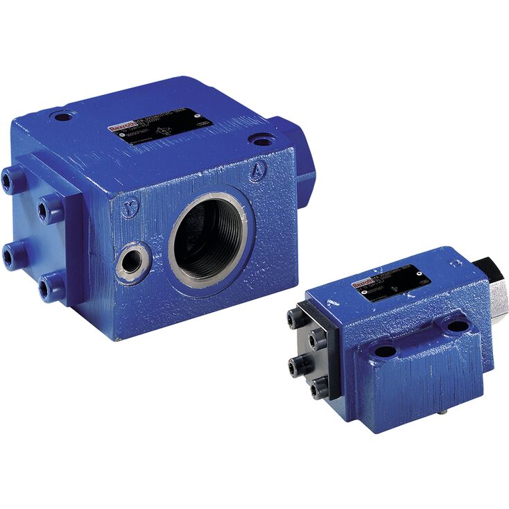
SV20 PA1-4X IN010
Rexroth
R983040193
用于底板安装。
油口布置符合ISO 5781-06-07-0-00(NG10)、ISO 5781-08-10-0-00(NG20)及ISO 5781-10-13-0-00(NG32)。
用于螺纹连接。
用于对一个执行器油口进行无泄漏封闭。
先导油内部回油。
可选带预开启的版本,实现阻尼释放。
可选不同开启压力。
单向阀安装套件可单独提供。
防腐蚀结构。
SV型截止阀是可液控开启的单向阀,适于底板安装或螺纹连接,即使长时间停机,也能无泄漏封闭一个执行器油口。
该阀主要由阀体(1)、座阀锥(2)、压缩弹簧(3)、控制阀芯(4),以及可选的球座式预开启阀(5)组成。
无需外部先导压力,油液即可由A经座阀流至B;反向流动时,座阀以液压密封方式关闭。
条件:p A > p B + 开启压力(压缩弹簧)。
当 X 口的先导压力足够高时,控制阀芯(4)向球座阀(5)的方向移动(“A”型),并将座阀阀芯(2)推离阀座。由此可实现双向自由流动,即主动保持开启。
要确保座阀能够主动开启,控制阀芯(4)两侧的压力比,与控制阀芯(4)或座阀阀芯(2)的面积比同样重要。
SV型采用较大环形面积A3(8),在接通pA时形成带预开启“A”及不带预开启“B”的版本。
“A”版本,带预开启。
该阀另带预开启功能。X口加压使控制阀芯(4)右移,先将球(5)推离阀座,然后推开座阀锥(2)。
说明:
“A”版本:
具有较大控制开启比的两级结构,可在较低先导压力下可靠卸荷。
通过对执行器侧受压容积进行阻尼卸压,避免切换冲击。
“B”版本:
不带预开启功能的阀可能使封闭的受压容积突然卸压,由此产生的切换冲击可能造成所装元件过早磨损,并产生噪声。
6 | Area A1 (seat poppet) |
7 | Area A2 (ball) |
8 | AreaA 3 (control spool) |
9 | Area A4 (control spool) |
注意:
更换堵头(10)、(11)可将SV型改为SL型。这两个堵头中必须始终安装一个。
NG | Plug (10) | Plug (11) |
10 | M3 | M6 |
20 | M4 | M6 |
30 | M4 | M6 |
01 | 02 | 03 | 04 | 05 | 06 | 07 | 08 | 09 | 10 | 11 | 12 | 13 | 14 | |||
S | V | – | 4X | / | – | * |
01 | Check valve | S |
02 | Pilot oil return, internal | V |
03 | Size 10 | 10 |
Size 20 | 20 | |
Size 32 | 30 | |
Type of connection | ||
04 | Subplate mounting | P |
Threaded connection | G | |
05 | With pre-opening | A |
Without pre-opening | B | |
Cracking pressure | ||
06 | See characteristic curves (A → B) | 1 |
2 | ||
3 | ||
4 | ||
07 | Component series 40 … 49 (40 … 49: unchanged installation and mounting dimensions) | 4X |
Spool position monitoring | ||
08 | Without position switch | no code |
With position switch 1) | QMG24 | |
For more information see "Electrical connection" | ||
Orifice fitting channel Y | ||
09 | Channel Y closed (standard) | Y99 |
Orifice Ø** in channel Y 2) | Y** | |
Seal material | ||
10 | NBR seals | N |
FKM seals | V | |
Observe compatibility of seals with hydraulic fluid used. (Other seals upon request) | ||
Corrosion resistance | ||
11 | None | no code |
Improved corrosion protection (240 h salt spray test according to EN ISO 9227) | J3 | |
12 | Standard | no code |
Pilot pressure ppilot from channel X | SO168 | |
Control open spool with shaft sealing (between channel X–Y and Y–A) | SO286 | |
Connection thread (versions with threaded connection "G" only) | ||
13 | Pipe thread "G" according to ISO 228-1 | no code |
Pipe thread “UNF/UN” according to ANSI/ASME B 1.1 | /12 | |
14 | Further details in the plain text | * |
| 1) | Only version "B3" |
| 2) | Order example: ** = dimension in mm x 10 – e.g. orifice Ø1,2 mm in channel Y = "Y12" |
Size | 10 | 20 | 32 | ||
Weight | Subplate mounting | kg | 1.8 | 4.7 | 7.8 |
Threaded connection | kg | 2.1 | 5.4 | 10 | |
Installation position | any | ||||
Ambient temperature range | NBR seals | °C | -30 … +80 | ||
FKM seals | °C | -20 … +80 | |||
MTTFD values according to EN ISO 13849 1) | Years | 150 | |||
Maximum storage time 2) | Months | 12 | |||
| 1) | For further details, see data sheet 08012 |
| 2) | If the storage conditions are observed; refer to the operating instructions 07600-B |
Size | 10 | 20 | 32 | ||
Maximum operating pressure | bar | 315 | |||
Cracking pressure | bar | 1.5 / 3 / 6 / 10 | 2.5 / 5 / 7.5 / 10 | 2.5 / 5 / 8 / 10 | |
Minimum pilot pressure | bar | 5 | |||
Maximum pilot pressure | bar | 315 | |||
Maximum flow | See characteristic curves | ||||
Direction of flow | Free from A → B, from B → A by opening | ||||
Hydraulic fluid | see table below | ||||
Hydraulic fluid temperature range | NBR seals | °C | -30 … +80 | ||
FPM seals | °C | -20 … +80 | |||
Viscosity range | mm²/s | 2.8 … 500 | |||
Maximum admissible degree of contamination of the hydraulic fluid, cleanliness class according to ISO 4406 (c) 1) | Class 20/18/15 | ||||
Pilot volume | Port X | cm³ | 2.5 | 10.8 | 19.27 |
Control area A1 2) | cm² | 1.33 | 3.46 | 5.72 | |
Control area A2 2) | cm² | 0.33 | 0.7 | 1.33 | |
Control area A3 2) | cm² | 3.8 | 10.17 | 16.61 | |
Control area A4 2) | cm² | 0.79 | 1.13 | 1.54 | |
| 1) | The cleanliness classes specified for the components must be adhered to in hydraulic systems. Effective filtration prevents faults and simultaneously increases the life cycle of the components. For the selection of the filters, see www.boschrexroth.com/filter. |
| 2) | Areas according to sectional drawing, see "Product description" |
Hydraulic fluid | Classification | Suitable sealing materials | Standards | Data sheet | |
Mineral oils | HL, HLP, HLPD, HVLP, HVLPD | NBR, FKM | DIN 51524 | 90220 | |
Bio-degradable | Insoluble in water | HETG 1) | NBR, FKM | ISO 15380 | 90221 |
HEES 1) | FKM | ||||
Soluble in water | HEPG 1) | FKM | ISO 15380 | ||
Flame-resistant | Water-free | HFDU (glycol base) | FKM | ISO 12922 | 90222 |
HFDU (ester base) 1) | FKM | ||||
HFDR | FKM | ||||
Containing water | HFC (Fuchs Hydrotherm 46M, Petrofer Ultra Safe 620) 1) | NBR | ISO 12922 | 90223 | |
Important information on hydraulic fluids:
| |||||
| 1) | Not recommended for corrosion-protected version "J3" (contains zinc) |
Dimensions in mm
| |
Required surface quality of the valve contact surface |
1 | Port Y closed |
2 | Name plate |
3 | Locking pin |
4 | Identical seal rings for ports A and B |
5 | Valve with cracking pressure Version "1" and "2" (dimension L2) |
6 | Valve with cracking pressure version "3" and "4" (dimension L3) |
7.1 | 6 valve mounting bores at NG32 |
8 | Porting pattern according to ISO 5781 |
9 | Version without position switch |
10 | Version with position switch "QMG24" (circuitry see "Electrical connection") |
NG | L1 | L2 | L3 | L4 | L5 | L6 | L7 | L8 | L9 | L11 | L12 | L13 | L14 | B1 | B2 | B3 | B4 | B6 | H1 | H2 | H3 |
mm | mm | mm | mm | mm | mm | mm | mm | mm | mm | mm | mm | mm | mm | mm | mm | mm | mm | mm | mm | mm | |
| 10 | 100.8 | 15.5 | 15.5 | 87.8 | 13 | 42.9 | 18.5 | 7.2 | 35.8 | 21.5 | - | 31.8 | 105 | 84 | 67.7 | 44 | 58.8 | 33.3 | 51 | 29 | 36 |
| 20 | 135 | 17.7 | 47.7 | 117 | 18 | 60.3 | 27.5 | 11.1 | 49.2 | 20.6 | - | 44.5 | 96.5 | 100 | 79.4 | 67 | 73 | 39.7 | 81 | 45 | 55 |
| 32 | 156.1 | 36.1 | 46.1 | 134 | 22.1 | 84.2 | 39 | 16.7 | 67.5 | 24.6 | 42.1 | 62.7 | 117 | 118 | 96.8 | 75 | 92.8 | 48.4 | 85 | 42.5 | 70 |
Size | Quantity | Hexagon socket head cap screws | Material number |
10 | 4 | ISO 4762 - M10 x 50 - 10.9 Tightening torque MA = 75 Nm ±20 % | - |
20 | 4 | ISO 4762 - M10 x 70 - 10.9 Tightening torque MA = 75 Nm ±20 % | - |
32 | 6 | ISO 4762 - M10 x 85 - 10.9 Tightening torque MA = 75 Nm ±20 % | - |
Notice:
The specified tightening torques were calculated with total friction coefficient μtotal = 0.09 ... 0.14; adjust in case of modified surfaces.
Subplates (separate order)
with porting pattern according to ISO 5781-06-07-0-00 (NG10), ISO 5781-08-10-0-00 (NG20), ISO 5781-10-13-0-00 (NG32) see data sheet 45100.
Dimensions in mm
1 | Port Y closed |
2 | Name plate |
5 | Valve with cracking pressure Version "1" and "2" (dimension L2) |
6 | Valve with cracking pressure version "3" and "4" (dimension L3) |
7.2 | 2 valve mounting bores |
9 | Version without position switch |
10 | Version with position switch "QMG24" (circuitry see "Electrical connection") |
Ports
NG | A | B | X | Y |
"G" | "UNF/UN" | "G" | "UNF/UN" | |
| 10 | G1/2 | 3/4-16 UNF | G1/4 | 7/16-20 UN |
| 20 | G1 | 1 5/16-12 UN | G1/4 | 7/16-20 UN |
| 32 | G1 1/2 | 1 7/8-12 UN | G1/4 | 7/16-20 UN |
Size | Quantity | Hexagon socket head cap screws | Material number |
10 | 2 | ISO 4762 - M10 x 60 - 10.9 | - |
20 | 2 | ISO 4762 - M10 x 85 - 10.9 | - |
32 | 2 | ISO 4762 - M10 x 100 - 10.9 | - |
Material number | Male thread | Internal thread | Seal (separate order) | |
NBR | FKM | |||
R900173685 | G1 | G3/4 | R900012475 | R900012509 |
R900173689 | G1 1/2 | G1 1/4 | R900012477 | R900012511 |