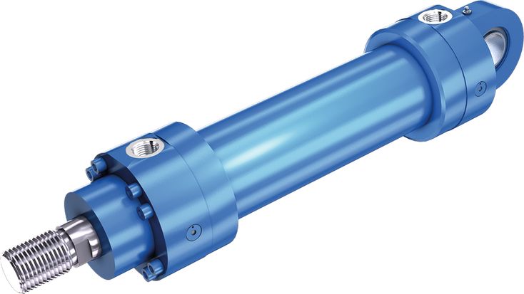
CDH2XC
标准:DIN 24333、ISO 6022。
六种安装方式。
01 |
02 |
03 |
04 |
05 |
06 |
07 |
08 |
09 |
10 |
11 |
12 |
13 |
14 |
15 |
16 |
||||
CD |
H2 |
/ |
/ |
/ |
XC |
3X |
/ |
01 |
Single rod cylinder |
CD |
|
02 |
Series |
H2 |
|
Types of mounting |
|||
03 |
Swivel eye at cylinder base |
MP3 |
|
Self-aligning clevis at cylinder base |
MP5 |
||
Round flange at the cylinder head |
MF3 |
||
Round flange at the cylinder base |
MF4 |
||
Trunnion |
MT42) |
||
Foot mounting |
MS218) |
||
04 |
Piston Ø (ØAL) 40 \u2026 320 mm |
... |
|
05 |
Piston rod Ø (ØMM) 25 \u2026 220 mm |
... |
|
06 |
Stroke length in mm3) |
... |
|
Protection class for ATEX version |
|||
07 |
Design safety |
XC |
|
08 |
Component series 30 ... 39 (30 ... 39: unchanged installation and connection dimensions) |
3X |
|
Line connection / version |
|||
09 |
According to ISO 1179-1 (pipe thread ISO 228-1) |
B |
|
According to ISO 9974-1 (metric thread ISO 261) |
M33) |
||
Flange connection according to ISO 6162-1 tab. 2 type 1 (≙ SAE 3000 PSI) |
F4; 21) |
||
Flange connection according to ISO 6162-2 tab. 2 type 1 (≙ SAE 6000 PSI) |
D4; 9) |
||
Flange connection according to ISO 6164 tab. 1 |
K1; 4) |
||
Flange connection according to ISO 6164 tab. 2 |
H4) |
||
Line connection/position at cylinder head |
|||
10 |
View to piston rod30) |
|
1 |
2 |
|||
3 |
|||
4 |
|||
Line connection/position at cylinder base |
|||
11 |
View to piston rod30) |
|
1 |
2 |
|||
3 |
|||
4 |
|||
Piston rod design |
|||
12 |
Hard chromium-plated |
C |
|
Hardened and hard chromium-plated |
H23) |
||
Nickel-plated and hard chromium-plated |
N24) |
||
Piston rod end |
|||
13 |
Thread for swivel head CGKD |
H |
|
With mounted swivel head CGKD |
F |
||
End position cushioning |
|||
14 |
Without end position cushioning |
U |
|
Both sides, self-adjusting |
D1) |
||
Both sides, adjustable |
E |
||
Seal design |
|||
15 |
For mineral oil HL, HLP and oil-in-water emulsion HFA |
Standard seal system |
M |
For mineral oil HL, HLP, oil-in-water emulsion HFA and water glycol HFC |
Servo quality/reduced friction |
T |
|
Chevron seal kits |
A |
||
For phosphoric acid esters HFR |
Servo quality/reduced friction |
S |
|
Chevron seal kits |
B |
||
Option |
|||
16 |
Additional options, fill fields for additional options |
Z |
|
Without additional options, do not fill fields for additional options |
W |
||
Fields for additional options |
||||||||
17 |
18 |
19 |
20 |
21 |
||||
Z |
||||||||
17 |
Without option |
W |
||||||
18 |
Additional guide rings |
F10) |
||||||
Without additional guide rings |
W |
|||||||
19 |
Measuring coupling, on both sides |
A |
||||||
Without measuring coupling |
W |
|||||||
20 |
Flanged grease nipple |
B |
||||||
Standard conical grease nipple |
W |
|||||||
21 |
Piston rod extension \u201cLY\u201d, specify in mm in plain text |
Y |
||||||
Without piston rod extension |
W |
|||||||
| 1) | Only piston Ø 40 \u2026 200 mm |
| 2) | Trunnion position freely selectable. When ordering, always specify the "XV" dimensions in the plain text in mm |
| 3) | For max. available stroke length see Technical data and for admissible stroke length (according to the kinking calculation) see Project planning information. |
| 4) | Not possible with MF4 |
| 9) | Only piston Ø 80 \u2026 320 mm |
| 10) | Seal designs A, B not possible; piston Ø 220 \u2026 320 mm standard |
| 18) | Not standardized |
| 21) | Only piston Ø 63 \u2026 200 mm |
| 23) | Only piston rod Ø 25 \u2026 140 mm |
| 24) | Only piston rod Ø 28 \u2026 160 mm |
| 30) | All graphical representations in the data sheet show position 1 |
| 33) | Version does not comply with ISO 6022 |
| Order examples: | |
| Without additional options: | |
| CDH2MT4/63/45/350XC3X/B11CHDMWW, XV = 300 mm |
|
| With additional options: | |
| CDH2MF3/80/56/500XC3X/B11CHDMZ WWAWW |
1 |
Word mark |
2 |
Material number |
3 |
Material short text |
4 |
Serial number |
5 |
Area / works number |
6 |
Date of production |
7 |
Catalog no. |
8 |
Designation of origin |
9 |
Customer or production order |
10 |
Customer's material number or additional information |
11 |
CE mark |
12 |
Explosion protection |
13 |
EX mark 1 |
14 |
EX mark 2 |
15 |
Test stamp (must be attached to the device) |
16 |
Assembly stamp (must be attached to the device) |
Name plate for piston Ø 63 \u2026 320 mm
Name plate for piston Ø 40, 50 mm
Separate adhesive label for ATEX units
Piston Ø 40, 50 mm
关于 ATEX 单元文件,您需要了解的信息。
ATEX 单元的文件适用于 Bosch Rexroth 液压缸的防爆型号,由以下两部分组成,物料号为 R901029463:
液压缸操作说明 07100-B/03.11,适用于拉杆式/冶金型,以及潜在爆炸危险区域用冶金型
技术数据表 17335-X
有关正确使用液压产品的更多信息,请参阅我们的出版物《液压产品通用产品信息》07008。
防爆信息:
不带位置测量系统的油缸
按指令 94/9/EC 标识:II 2G c T4
按指令 94/9/EC 标识:II 2D c T135 °C
环境温度 \u201320 °C ≤ Ta ≤ +80 °C
带位置测量系统的油缸
按指令 94/9/EC 标识:II 3G Ex e T4X
按指令 94/9/EC 标识:II 3D Ex tc T135 °C
环境温度 \u201320 °C ≤ Ta ≤ +59 °C
Installation position |
any | |
Primer coat |
Gentian blue (RAL 5010) | |
Minimum layer thickness of the priming 1) |
µm |
40 |
| 1) | Other colors upon request. With cylinders and attachment parts, the following surfaces are not primed or painted: ▶ All fit diameters to the customer\u2019s side ▶ Sealing surfaces for line connection ▶ Sealing surfaces for flange connection ▶ Position measurement system The unpainted surfaces are protected using a corrosion protection agent which is free from solvents. |
Nominal pressure 1) |
bar |
250 |
Minimum operating pressure (without load) 2) |
bar |
10 |
Static test pressure |
bar |
375 |
Reduced test pressure |
bar |
315 |
Operating viscosity range |
mm²/s |
12 \u2026 380 |
Maximum admissible degree of contamination of the hydraulic fluid, cleanliness class according to ISO 4406 (c) 3) |
Class 20/18/15 according to ISO 4406 (c) | |
Bleeding |
By default secured against screwing out | |
| 1) | Higher operating pressures upon request. The specified operating pressures apply to applications with shock-free operation with reference to excess pressure and/or external loads. With extreme loads like e. g. high sequence cycle, mounting elements and threaded piston rod connections must be designed for durability. |
| 2) | Depending on the application, a certain minimum pressure is required in order to guarantee good functioning of the cylinder. Without load, a minimum pressure of 10 bar is recommended for differential cylinders; for lower pressures as well as double-acting cylinders, please contact us. |
| 3) | The cleanliness classes specified for the components must be adhered to in hydraulic systems. Effective filtration prevents faults and simultaneously increases the life cycle of the components. For the selection of the filters, see www.boschrexroth.com/filter. |
Hydraulic fluid1) |
Classification |
Suitable sealing materials |
Standards |
Mineral oil |
HL, HLP |
FKM,NBR |
DIN 51524 |
Oil-in-water emulsion |
HFA |
FKM, NBR |
ISO 12922 |
Phosphoric acid esters |
HFDR |
FKM |
ISO 12922 |
Water glycol |
HFC |
upon request |
|
| 1) | For further information on hydraulic fluids refer to data sheet R.90223. |
Piston |
Piston rod |
with 0 mm stroke length |
per 100 mm stroke length |
|||
ØAL |
ØMM |
MP3/MP5 |
MF3/MF4 |
MT4 |
MS2 |
|
Weight without position measurement system |
||||||
mm |
kg |
kg |
kg |
kg |
kg |
|
| 40 | 25 mm / - | 7 | 9 | 9 | 9 | 0.9 |
| 28 mm / - | 7 | 9 | 9 | 9 | 1 | |
| 50 | 32 mm / - | 12 | 14 | 13 | 13 | 1.3 |
| 36 mm / - | 12 | 14 | 13 | 14 | 1.5 | |
| 63 | 40 mm / - | 20 | 21 | 21 | 21 | 2.3 |
| 45 mm / - | 20 | 21 | 21 | 21 | 2.6 | |
| 80 | 50 mm / - | 32 | 35 | 34 | 35 | 3.2 |
| 56 mm / - | 32 | 35 | 34 | 36 | 3.6 | |
| 100 | 63 mm / - | 51 | 54 | 54 | 55 | 5.2 |
| 70 mm / - | 51 | 55 | 54 | 56 | 5.7 | |
| 125 | 80 mm / - | 95 | 96 | 99 | 98 | 8.2 |
| 90 mm / - | 96 | 97 | 100 | 99 | 9.2 | |
| 140 | 90 mm / - | 131 | 132 | 136 | 137 | 10.7 |
| 100 mm / - | 132 | 133 | 137 | 138 | 11.9 | |
| 160 | 100 mm / - | 185 | 184 | 197 | 206 | 12.6 |
| 110 mm / - | 186 | 186 | 199 | 207 | 13.9 | |
| 180 | 110 mm / - | 255 | 253 | 264 | 274 | 14.7 |
| 125 mm / - | 256 | 253 | 267 | 277 | 16.8 | |
| 200 | 125 mm / - | 349 | 332 | 350 | 363 | 19 |
| 140 mm / - | 352 | 335 | 353 | 366 | 21.5 | |
| 220 | 140 mm / - | 527 | 512 | 546 | 518 | 27.1 |
| 160 mm / - | 527 | 512 | 546 | 518 | 30.9 | |
| 250 | 160 mm / - | 673 | 640 | 677 | 650 | 32.7 |
| 180 mm / - | 673 | 640 | 677 | 650 | 36.9 | |
| 280 | 180 mm / - | 976 | 966 | 1020 | 918 | 44.2 |
| 200 mm / - | 976 | 966 | 1020 | 918 | 48.8 | |
| 320 | 200 mm / - | 1251 | 1172 | 1223 | 1174 | 55.2 |
| 220 mm / - | 1251 | 1172 | 1223 | 1174 | 60.4 | |
Work and environmental conditions |
Seal versions |
|||||
M |
A |
B |
T |
S |
||
Medium/temperature |
Medium HL, HLP/operating temperature of medium \u201220 \u2026 +80 °C |
++ |
++ |
++ |
++ |
++ |
Medium HFA/operating temperature of medium +5 \u2026 +55 °C |
+/\u2012 |
+ |
+/\u2012 |
++ |
+/\u2012 |
|
Medium HFC/operating temperature of medium \u201220 \u2026 +60 °C |
\u2012 |
+/\u2012 |
\u2012 |
++ |
\u2012 |
|
Medium HFDR/operating temperature of medium \u201215 \u2026 +80 °C |
\u2012 |
\u2012 |
++ |
\u2012 |
++ |
|
Ambient and rod temperature in the area of the piston rod \u201220 \u2026 +80 °C1) |
++ |
++ |
+2) |
+ |
++2) |
|
Function/velocity \u2026 |
Static holding function more than 10 minutes: |
++ |
++ |
++ |
+ |
+ |
Static holding function short-time < 1 minute |
++ |
++ |
++ |
++ |
++ |
|
Robust application conditions: steel works, mining, thin ice |
++ |
++ |
++ |
\u2012 |
\u2012 |
|
Zero point control, hardly any amplitude, frequency ≤ 5 Hz, max. 5 minutes |
\u2012 |
\u2012 |
\u2012 |
++ |
++ |
|
Cylinder velocity ≥ 0.001 m/s stick-slip behavior |
++ |
\u2012 |
\u2012 |
++ |
++ |
|
Cylinder velocity 0.01 \u2026 0.5 m/s3) |
++ |
+ |
+ |
++ |
++ |
|
Cylinder velocity > 0.5 \u2026 ≤ 0.8 m/s3) |
\u2012 |
\u2012 |
\u2012 |
++ |
++ |
|
Stroke length > 1.0 m |
+/\u2012 |
++ |
++ |
++ |
++ |
|
Standstill period (wear) |
++ |
+/\u2012 |
\u2012 |
++ |
++ |
|
Undissolved air in the oil4) |
\u2012 |
\u2012 |
\u2012 |
+ |
+ |
|
| ++ = very good + = good +/\u2013 = conditional, depending on the application parameters \u2013 = inappropriate General technical data in corresponding data sheets will remain valid! Generally, a medium temperature of approx. 40 °C is recommended. The specified values are to be regarded as guidelines; depending on the case of application, it may be necessary to check the suitability of the seal system. |
|
| 1) | Moreover, observe the corresponding medium temperature range |
| 2) | Lower temperature limit \u201315 °C |
| 3) | Standard line connections not designed for that velocity |
| 4) | \u2012 = Seal is destroyed, + = Seal is not directly destroyed, leakage may occur |
Piston Ø |
Line connection |
Maximum stroke velocity 1) |
mm |
m/s |
|
| 40 | G1/2 | 0.31 |
| G1/2 | 0.31 | |
| 50 | G1/2 | 0.2 |
| G1/2 | 0.2 | |
| 63 | G3/4 | 0.28 |
| G3/4 | 0.28 | |
| 80 | G3/4 | 0.18 |
| G3/4 | 0.18 | |
| 100 | G1 | 0.2 |
| G1 | 0.2 | |
| 125 | G1 | 0.13 |
| G1 | 0.13 | |
| 140 | G1 1/4 | 0.16 |
| G1 1/4 | 0.16 | |
| 160 | G1 1/4 | 0.12 |
| G1 1/4 | 0.12 | |
| 180 | G1 1/4 | 0.1 |
| G1 1/4 | 0.1 | |
| 200 | G1 1/4 | 0.08 |
| G1 1/4 | 0.08 | |
| 220 | G1 1/2 | 0.09 |
| G1 1/2 | 0.09 | |
| 250 | G1 1/2 | 0.07 |
| G1 1/2 | 0.07 | |
| 280 | G1 1/2 | 0.06 |
| G1 1/2 | 0.06 | |
| 320 | G1 1/2 | 0.04 |
| G1 1/2 | 0.04 |
| 1) | Please observe the guideline on max. stroke velocities (with recommended flow velocity of 5 m/s in the line connection) in the table. Higher stroke velocities upon request. If the extension velocity is considerably higher than the retraction velocity of the piston rod, drag-out losses of the medium may result. If necessary, please consult us. |
Rexroth 油缸符合工业应用的可靠性建议。在额定压力的 70 %、活塞杆不承受负载、最大速度 0.5 m/s 的条件下,连续空载运行可达到 ≥ 10,000,000 次往复行程,或活塞累计行程 3,000 km,故障率低于 5 %。
边界条件与应用条件:
必须确保运动轴线,以及液压缸和活塞杆安装点的机械对中。应避免活塞杆与活塞导向部位承受侧向力。必要时,应考虑液压缸(MP3/MP5 或 MT4)或活塞杆的自重。
必须注意活塞杆和/或液压缸的屈曲长度/屈曲载荷(见“项目规划信息”)。
必须遵守与密封件适用性及负载有关的最大允许行程速度,同时确保密封件与所用流体类型的特性相容(见“技术参数”)。
运动至终端位置时,必须遵守最大允许速度/动能,并考虑外部载荷。危险:超压
液压缸在任何运行状态下,都必须遵守最大允许工作压力。应考虑环形面积与活塞面积之比所造成的压力增压,以及可能存在的节流部位。
应避免腐蚀性微细颗粒、蒸气、高温等有害环境影响,以及液压油的污染和劣化。
标准:
油缸的安装尺寸和安装方式符合 DIN 24333 与 ISO 6022。
验收:
每个油缸均按 Bosch Rexroth 标准测试,并符合 ISO 10100: 2001。
安全说明:
液压缸的装配、调试和维护必须遵守操作说明 07100-B!保养和维修必须由 Bosch Rexroth AG 或为此经过专门培训的人员执行。因非 Bosch Rexroth AG 执行的装配、维护或维修造成的损坏,不予保修。
液压缸检查清单:
若油缸的特性和/或应用参数偏离数据表所列数值,则只能按要求作为特殊型号提供。询价时,必须在液压缸检查清单(07200)中说明特性和/或应用参数的变化。
本清单不保证完整。如对介质相容性,或超出边界条件、应用条件的情况有疑问,请联系我们。
数据表中的所有图示均为示例,因此实际交付产品可能与图形不同。
Piston |
Piston rod |
Area ratio |
Areas |
Force at 160 bar |
Flow at 0.1 m/s |
Maximum available stroke length |
||||||
Piston |
Rod |
Ring |
Pressure |
Differential |
Traction |
Off |
Differential |
On |
||||
ØAL |
ØMM |
φ A1/A3 |
A1 |
A2 |
A3 |
F1 |
F2 |
F3 |
qV1 |
qV2 |
qV3 |
|
mm |
cm² |
cm² |
cm² |
kN |
kN |
kN |
l/min |
l/min |
l/min |
mm |
||
| 40 | 25 mm / - | 1.64 | 12.56 | 4.9 | 7.65 | 31.4 1) | 12.25 | 19.12 | 7.5 2) | 2.9 | 4.6 | 2000 |
| 28 mm / - | 1.96 | 12.56 | 6.16 | 6.4 | 31.4 1) | 15.4 | 16 | 7.5 2) | 3.7 | 3.8 | 2000 | |
| 50 | 32 mm / - | 1.69 | 19.63 | 8.04 | 11.59 | 49.1 1) | 20.12 | 28.98 | 11.8 2) | 4.8 | 7 | 2000 |
| 36 mm / - | 2.08 | 19.63 | 10.18 | 9.45 | 49.1 1) | 25.45 | 23.65 | 11.8 2) | 6.1 | 5.7 | 2000 | |
| 63 | 40 mm / - | 1.67 | 31.17 | 12.56 | 18.61 | 77.9 1) | 31.38 | 46.52 | 18.7 2) | 7.5 | 11.2 | 2000 |
| 45 mm / - | 2.04 | 31.17 | 15.9 | 15.27 | 77.9 1) | 39.75 | 38.15 | 18.7 2) | 9.5 | 9.2 | 2000 | |
| 80 | 50 mm / - | 1.66 | 50.26 | 19.63 | 30.63 | 125.65 1) | 49.07 | 76.58 | 30.2 2) | 11.8 | 18.4 | 2000 |
| 56 mm / - | 1.96 | 50.26 | 24.63 | 25.63 | 125.65 1) | 61.55 | 64.1 | 30.2 2) | 14.8 | 15.4 | 2000 | |
| 100 | 63 mm / - | 1.66 | 78.54 | 31.16 | 47.38 | 196.35 1) | 77.93 | 118.42 | 47.1 2) | 18.7 | 28.4 | 3000 |
| 70 mm / - | 1.96 | 78.54 | 38.48 | 40.06 | 196.35 1) | 96.2 | 100.15 | 47.1 2) | 23.1 | 24 | 3000 | |
| 125 | 80 mm / - | 1.69 | 122.72 | 50.24 | 72.48 | 306.75 1) | 125.62 | 181.13 | 73.6 2) | 30.1 | 43.5 | 3000 |
| 90 mm / - | 2.08 | 122.72 | 63.62 | 59.1 | 306.75 1) | 159.05 | 147.7 | 73.6 2) | 38.2 | 35.4 | 3000 | |
| 140 | 90 mm / - | 1.7 | 153.94 | 63.62 | 90.32 | 384.75 1) | 159.05 | 225.7 | 92.4 2) | 38.2 | 54.2 | 3000 |
| 100 mm / - | 2.04 | 153.94 | 78.54 | 75.4 | 384.75 1) | 196.35 | 188.4 | 92.4 2) | 47.1 | 45.3 | 3000 | |
| 160 | 100 mm / - | 1.64 | 201.06 | 78.54 | 122.5 | 502.5 1) | 196.35 | 306.15 | 120.6 2) | 47.1 | 73.5 | 3000 |
| 110 mm / - | 1.9 | 201.06 | 95.06 | 106 | 502.5 1) | 237.65 | 264.85 | 120.6 2) | 57 | 63.6 | 3000 | |
| 180 | 110 mm / - | 1.6 | 254.47 | 95.06 | 159.43 | 636.17 1) | 237.65 | 398.52 | 152.7 2) | 57 | 95.7 | 3000 |
| 125 mm / - | 1.93 | 254.47 | 122.72 | 131.75 | 636.17 1) | 306.8 | 329.37 | 152.7 2) | 73.6 | 79.1 | 3000 | |
| 200 | 125 mm / - | 1.64 | 314.16 | 122.72 | 191.44 | 785.25 1) | 306.8 | 478.45 | 188.5 2) | 73.6 | 114.9 | 3000 |
| 140 mm / - | 1.96 | 314.16 | 153.96 | 160.2 | 785.25 1) | 384.9 | 400.35 | 188.5 2) | 92.4 | 96.1 | 3000 | |
| 220 | 140 mm / - | 1.68 | 380.1 | 153.96 | 226.2 | 950.3 1) | 384.9 | 565.5 | 228.1 2) | 92.4 | 135.7 | 6000 |
| 160 mm / - | 2.12 | 380.1 | 201 | 179.1 | 950.3 1) | 502.6 | 447.7 | 228.1 2) | 120.7 | 107.4 | 6000 | |
| 250 | 160 mm / - | 1.69 | 490.8 | 201 | 289.8 | 1227.2 1) | 502.6 | 724.5 | 294.5 2) | 120.7 | 173.8 | 6000 |
| 180 mm / - | 2.08 | 490.8 | 254.4 | 236.4 | 1227.2 1) | 636.2 | 590 | 294.5 2) | 152.7 | 141.8 | 6000 | |
| 280 | 180 mm / - | 1.7 | 615.7 | 254.4 | 361.3 | 1539.4 1) | 636.2 | 903.2 | 369.4 2) | 152.7 | 216.7 | 6000 |
| 200 mm / - | 2.04 | 615.7 | 314.1 | 301.6 | 1539.4 1) | 785.4 | 753.9 | 369.4 2) | 188.5 | 180.9 | 6000 | |
| 320 | 200 mm / - | 1.64 | 804.2 | 314.1 | 490.1 | 2010.6 1) | 785.4 | 1225.2 | 482.5 2) | 188.5 | 294 | 6000 |
| 220 mm / - | 1.9 | 804.2 | 380.1 | 424.2 | 2010.6 1) | 950.3 | 1060.3 | 482.5 2) | 228.1 | 254.4 | 6000 | |
| 1) | Theoretical static cylinder force (without consideration of the efficiency and admissible load for attachment parts such as swivel heads, plates, or valves, etc.) |
| 2) | Stroke velocity |
Installation dimensions |
WC |
XC2) |
XO2) |
XS1; 2) |
XV2) |
ZP2) |
|
Mounting type |
MF3 |
MP3 |
MP5 |
MS2 |
MT4 |
MF4 |
|
Stroke length in mm |
Tolerances in mm |
Stroke tolerances in mm |
|||||
≤ 1.250 |
±2 |
±1,5 |
±1,5 |
±2 |
±2 |
±1,5 |
±2 |
> 1.250\u2026 ≤ 3.150 |
±4 |
±3 |
±3 |
±4 |
±4 |
±3 |
+5 |
> 3.150p \u2026 ≤ 6.000 |
±8 |
+5 |
+5 |
±8 |
±8 |
+5 |
±8 |
| 1) | Not standardized |
| 2) | Including stroke length |
| 3) | Stroke tolerances must not be added to the tolerances listed in this table. |
所有油缸默认在缸头和缸底配备专利安全排气装置,以防意外旋出。
该接口可安装带单向阀的测量接头,用于测压或无污染排气。测量接头具有单向阀功能,因此也可在系统带压时连接。
| 1) | Bleeding: with view to the piston rod, the position is always offset by 90° in relation to the line connection (clockwise) |
供货范围:测量接头 G1/4
MESSKUPPLUNG AB 20-11/K1 G1/4,配 NBR 密封圈
物料号 R900009090
MESSKUPPLUNG AB 20-11/K1V G1/4,配 FKM 密封圈
物料号 R900001264
| 1) | Bleeding: with view to the piston rod, the position is always offset by 90° in relation to the line connection (clockwise) |
| 2) | Throttle valve only with end position cushioning "E" (180° for bleeding) |
| 3) | Standard version \u201cW\u201d Lubricating nipple, cone head form A according to DIN 71412 |
| 4) | Related bolt Ø f8 |
| 5) | For the equipotential bonding refer to dimensions |
MP3: with seal design \u201cA\u201d, \u201cB\u201d, and AL Ø 160 \u2026 320 mm
| 1) | For the equipotential bonding refer to dimensions |
ØAL |
ØMM |
KK |
A |
NV |
ØD |
ØDA |
ØD4 1) |
EE 2) 3) |
EE 2) 4) |
Y |
PJ |
X1 |
WA |
XC |
L |
L1 |
MR |
M1 |
ØCD |
EW |
ØRA 7) |
VE 7) |
ØRA 8) |
VE 8) |
||
mm |
mm |
mm |
mm |
mm |
mm |
mm |
mm |
mm |
mm |
mm |
mm |
mm |
mm |
mm |
mm |
mm |
mm |
mm |
mm |
mm |
||||||
| 40 | 25 mm / - | M20 x 1.5 | 28 | 19 | 88 | 52 | 34 | G1/2 | M22 x 1.5 | 83 | 120 | 41 | 18 | 282 | 53 | 8 | 32 | 32 | 25 | H9 |
25 | h12 |
52 | 29 | 88 | - |
| 28 mm / - | M20 x 1.5 | 28 | 22 | 88 | 52 | 34 | G1/2 | M22 x 1.5 | 83 | 120 | 41 | 18 | 282 | 53 | 8 | 32 | 32 | 25 | H9 |
25 | h12 |
52 | 29 | 88 | - | |
| 50 | 32 mm / - | M27 x 2 | 36 | 27 | 102 | 62 | 34 | G1/2 | M22 x 1.5 | 98 | 120 | 48.5 | 18 | 305 | 61 | 8 | 40 | 40 | 32 | H9 |
32 | h12 |
63 | 29 | 102 | - |
| 36 mm / - | M27 x 2 | 36 | 30 | 102 | 62 | 34 | G1/2 | M22 x 1.5 | 98 | 120 | 48.5 | 18 | 305 | 61 | 8 | 40 | 40 | 32 | H9 |
32 | h12 |
63 | 29 | 102 | - | |
| 63 | 40 mm / - | M33 x 2 | 45 | 32 | 120 | 78 | 42 | G3/4 | M27 x 2 | 112 | 133 | 56.5 | 21 | 348 | 74 | 8 | 50 | 50 | 40 | H9 |
40 | h12 |
75 | 32 | 120 | - |
| 45 mm / - | M33 x 2 | 45 | 36 | 120 | 78 | 42 | G3/4 | M27 x 2 | 112 | 133 | 56.5 | 21 | 348 | 74 | 8 | 50 | 50 | 40 | H9 |
40 | h12 |
75 | 32 | 120 | - | |
| 80 | 50 mm / - | M42 x 2 | 56 | 41 | 145 | 95 | 42 | G3/4 | M27 x 2 | 120 | 155 | 69.5 | 24 | 395 | 90 | 10 | 63 | 63 | 50 | H9 |
50 | h12 |
90 | 36 | 145 | - |
| 56 mm / - | M42 x 2 | 56 | 46 | 145 | 95 | 42 | G3/4 | M27 x 2 | 120 | 155 | 69.5 | 24 | 395 | 90 | 10 | 63 | 63 | 50 | H9 |
50 | h12 |
90 | 36 | 145 | - | |
| 100 | 63 mm / - | M48 x 2 | 63 | 50 | 170 | 125 | 47 | G1 | M33 x 2 | 134 | 171 | 82 | 27 | 442 | 102 | 12 | 71 | 71 | 63 | H9 |
63 | h12 |
110 | 41 | 170 | - |
| 70 mm / - | M48 x 2 | 63 | 60 | 170 | 125 | 47 | G1 | M33 x 2 | 134 | 171 | 82 | 27 | 442 | 102 | 12 | 71 | 71 | 63 | H9 |
63 | h12 |
110 | 41 | 170 | - | |
| 125 | 80 mm / - | M64 x 3 | 85 | 65 | 206 | 150 | 47 | G1 | M33 x 2 | 153 | 205 | 100.5 | 31 | 520 | 124 | 16 | 90 | 90 | 80 | H9 |
80 | h12 |
132 | 45 | 206 | - |
| 90 mm / - | M64 x 3 | 85 | 75 | 206 | 150 | 47 | G1 | M33 x 2 | 153 | 205 | 100.5 | 31 | 520 | 124 | 16 | 90 | 90 | 80 | H9 |
80 | h12 |
132 | 45 | 206 | - | |
| 140 | 90 mm / - | M72 x 3 | 90 | 75 | 226 | 170 | 58 | G1 1/4 | M42 x 2 | 166 | 219 | 109.5 | 31 | 580 | 149 | 16 | 100 | 100 | 90 | H9 |
90 | h12 |
145 | 45 | 226 | - |
| 100 mm / - | M72 x 3 | 90 | 85 | 226 | 170 | 58 | G1 1/4 | M42 x 2 | 166 | 219 | 109.5 | 31 | 580 | 149 | 16 | 100 | 100 | 90 | H9 |
90 | h12 |
145 | 45 | 226 | - | |
| 160 | 100 mm / - | M80 x 3 | 95 | 85 | 265 | 190 | 58 | G1 1/4 | M42 x 2 | 185 | 235 | 129.5 | 35 | 617 | 150 | 16 | 112 | 112 | 100 | H9 |
100 | h12 |
160 | 50 | 200 | 50 |
| 110 mm / - | M80 x 3 | 95 | 95 | 265 | 190 | 58 | G1 1/4 | M42 x 2 | 185 | 235 | 129.5 | 35 | 617 | 150 | 16 | 112 | 112 | 100 | H9 |
100 | h12 |
160 | 50 | 200 | 50 | |
| 180 | 110 mm / - | M90 x 3 | 105 | 95 | 292 | 210 | 58 | G1 1/4 | M42 x 2 | 194 | 264 | 143.5 | 40 | 690 | 180 | 20 | 129 | 129 | 110 | H9 |
110 | h12 |
185 | 55 | 220 | 55 |
| 125 mm / - | M90 x 3 | 105 | 110 | 292 | 210 | 58 | G1 1/4 | M42 x 2 | 194 | 264 | 143.5 | 40 | 690 | 180 | 20 | 129 | 129 | 110 | H9 |
110 | h12 |
185 | 55 | 220 | 55 | |
| 200 | 125 mm / - | M100 x 3 | 112 | 110 | 306 | 235 | 58 | G1 1/4 | M42 x 2 | 220 | 278 | 150.5 | 40 | 756 | 206 | 20 | 145 | 145 | 125 | H9 |
125 | h12 |
200 | 61 | 235 | 61 |
| 140 mm / - | M100 x 3 | 112 | 120 | 306 | 235 | 58 | G1 1/4 | M42 x 2 | 220 | 278 | 150.5 | 40 | 756 | 206 | 20 | 145 | 145 | 125 | H9 |
125 | h12 |
200 | 61 | 235 | 61 | |
| 220 | 140 mm / - | M125 x 4 | 125 | 120 | 355 | 270 | 65 | G1 1/2 | M48 x 2 5) | 244 | 326 | 174 | 42 | 890 | 253 | 20 | 179 6) | 187 6) | 160 | H9 |
160 | h12 |
235 | 71 | 270 | 71 |
| 160 mm / - | M125 x 4 | 125 | 140 | 355 | 270 | 65 | G1 1/2 | M48 x 2 5) | 244 | 326 | 174 | 42 | 890 | 253 | 20 | 179 6) | 187 6) | 160 | H9 |
160 | h12 |
235 | 71 | 270 | 71 | |
| 250 | 160 mm / - | M125 x 4 | 125 | 140 | 395 | 305 | 65 | G1 1/2 | M48 x 2 5) | 257 | 326 | 194 | 42 | 903 | 253 | 24 | 179 6) | 187 6) | 160 | H9 |
160 | h12 |
250 | 71 | 300 | 71 |
| 180 mm / - | M125 x 4 | 125 | 160 | 395 | 305 | 65 | G1 1/2 | M48 x 2 5) | 257 | 326 | 194 | 42 | 903 | 253 | 24 | 179 6) | 187 6) | 160 | H9 |
160 | h12 |
250 | 71 | 300 | 71 | |
| 280 | 180 mm / - | M160 x 4 | 160 | 160 | 445 | 343 | 65 | G1 1/2 | M48 x 2 5) | 290 | 375 | 220.5 | 48 | 1072 | 320 | 30 | 230 6) | 240 6) | 200 | H9 |
200 | h12 |
295 | 88 | 325 | 88 |
| 200 mm / - | M160 x 4 | 160 | 180 | 445 | 343 | 65 | G1 1/2 | M48 x 2 5) | 290 | 375 | 220.5 | 48 | 1072 | 320 | 30 | 230 6) | 240 6) | 200 | H9 |
200 | h12 |
295 | 88 | 325 | 88 | |
| 320 | 200 mm / - | M160 x 4 | 160 | 180 | 490 | 394 | 65 | G1 1/2 | M48 x 2 5) | 282 | 391 | 243 | 48 | 1080 | 320 | 30 | 231 6) | 241 6) | 200 | H9 |
200 | h12 |
320 | 88 | 365 | 88 |
| 220 mm / - | M160 x 4 | 160 | 200 | 490 | 394 | 65 | G1 1/2 | M48 x 2 5) | 282 | 391 | 243 | 48 | 1080 | 320 | 30 | 231 6) | 241 6) | 200 | H9 |
200 | h12 |
320 | 88 | 365 | 88 | |
| 1) | Ø D4 max. 0.5 mm deep |
| 2) | Flange connections see separate table |
| 3) | Line connection \u201cB\u201d and \u201cC\u201d |
| 4) | Line connection \u201cM" |
| 5) | Thread size does not correspond to ISO 6022; M50 x 2 available upon request |
| 6) | The specified dimensions are maximum values, tolerance classes 342 according to ISO 9013 Thermal cutting |
| 7) | Dimensions for cylinders with seal design M, T, and S |
| 8) | Dimensions for cylinders with seal design A and B |
| 1) | Bleeding: with view to the piston rod, the position is always offset by 90° in relation to the line connection (clockwise) |
| 2) | Throttle valve only with end position cushioning "E" (180° for bleeding) |
| 3) | Standard version \u201cW\u201d Lubricating nipple, cone head form A according to DIN 71412 |
| 4) | Related bolt Ø f8 |
| 5) | For the equipotential bonding refer to dimensions |
MP5: with seal design \u201cA\u201d, \u201cB\u201d, and AL Ø 160 \u2026 320 mm
| 1) | For the equipotential bonding refer to dimensions |
ØAL |
ØMM |
KK |
A |
NV |
ØD |
ØDA |
ØD4 1) |
EE 2) 3) |
EE 2) 4) |
Y |
PJ |
X1 |
WA |
XO |
LT |
L1 |
MS |
M1 |
ØCX |
EP |
EX |
ØRA 8) |
VE 8) |
ØRA 9) |
VE 9) |
Z |
||
mm |
mm |
mm |
mm |
mm |
mm |
mm |
mm |
mm |
mm |
mm |
mm |
mm |
mm |
mm |
mm 7) |
mm |
mm |
mm |
mm |
mm |
mm |
° |
||||||
| 40 | 25 mm / - | M20 x 1.5 | 28 | 19 | 88 | 52 | 34 | G1/2 | M22 x 1.5 | 83 | 120 | 41 | 18 | 282 | 53 | 8 | 32 | 32 | 25 | H7 |
22 | 25 | h12 |
52 | 29 | 88 | - | 2 |
| 28 mm / - | M20 x 1.5 | 28 | 22 | 88 | 52 | 34 | G1/2 | M22 x 1.5 | 83 | 120 | 41 | 18 | 282 | 53 | 8 | 32 | 32 | 25 | H7 |
22 | 25 | h12 |
52 | 29 | 88 | - | 2 | |
| 50 | 32 mm / - | M27 x 2 | 36 | 27 | 102 | 62 | 34 | G1/2 | M22 x 1.5 | 98 | 120 | 48.5 | 18 | 305 | 61 | 8 | 40 | 40 | 32 | H7 |
27 | 32 | h12 |
63 | 29 | 102 | - | 4 |
| 36 mm / - | M27 x 2 | 36 | 30 | 102 | 62 | 34 | G1/2 | M22 x 1.5 | 98 | 120 | 48.5 | 18 | 305 | 61 | 8 | 40 | 40 | 32 | H7 |
27 | 32 | h12 |
63 | 29 | 102 | - | 4 | |
| 63 | 40 mm / - | M33 x 2 | 45 | 32 | 120 | 78 | 42 | G3/4 | M27 x 2 | 112 | 133 | 56.5 | 21 | 248 | 74 | 8 | 50 | 50 | 40 | H7 |
32 | 40 | h12 |
75 | 32 | 120 | - | 4 |
| 45 mm / - | M33 x 2 | 45 | 36 | 120 | 78 | 42 | G3/4 | M27 x 2 | 112 | 133 | 56.5 | 21 | 248 | 74 | 8 | 50 | 50 | 40 | H7 |
32 | 40 | h12 |
75 | 32 | 120 | - | 4 | |
| 80 | 50 mm / - | M42 x 2 | 65 | 41 | 145 | 95 | 42 | G3/4 | M27 x 2 | 120 | 155 | 69.5 | 24 | 395 | 90 | 10 | 63 | 63 | 50 | H7 |
40 | 50 | h12 |
90 | 36 | 145 | - | 4 |
| 56 mm / - | M42 x 2 | 65 | 46 | 145 | 95 | 42 | G3/4 | M27 x 2 | 120 | 155 | 69.5 | 24 | 395 | 90 | 10 | 63 | 63 | 50 | H7 |
40 | 50 | h12 |
90 | 36 | 145 | - | 4 | |
| 100 | 63 mm / - | M48 x 2 | 63 | 50 | 170 | 125 | 47 | G1 | M33 x 2 | 134 | 171 | 82 | 27 | 442 | 102 | 12 | 71 | 71 | 63 | H7 |
52 | 63 | h12 |
110 | 41 | 170 | - | 4 |
| 70 mm / - | M48 x 2 | 63 | 60 | 170 | 125 | 47 | G1 | M33 x 2 | 134 | 171 | 82 | 27 | 442 | 102 | 12 | 71 | 71 | 63 | H7 |
52 | 63 | h12 |
110 | 41 | 170 | - | 4 | |
| 125 | 80 mm / - | M64 x 3 | 85 | 65 | 206 | 150 | 47 | G1 | M33 x 2 | 153 | 205 | 100.5 | 31 | 520 | 124 | 16 | 90 | 90 | 80 | H7 |
66 | 80 | h12 |
132 | 45 | 206 | - | 4 |
| 90 mm / - | M64 x 3 | 85 | 75 | 206 | 150 | 47 | G1 | M33 x 2 | 153 | 205 | 100.5 | 31 | 520 | 124 | 16 | 90 | 90 | 80 | H7 |
66 | 80 | h12 |
132 | 45 | 206 | - | 4 | |
| 140 | 90 mm / - | M72 x 3 | 90 | 75 | 226 | 170 | 58 | G1 1/4 | M42 x 2 | 166 | 219 | 109.5 | 31 | 580 | 149 | 16 | 100 | 100 | 90 | H7 |
72 | 90 | h12 |
145 | 45 | 226 | - | 4 |
| 100 mm / - | M72 x 3 | 90 | 85 | 226 | 170 | 58 | G1 1/4 | M42 x 2 | 166 | 219 | 109.5 | 31 | 580 | 149 | 16 | 100 | 100 | 90 | H7 |
72 | 90 | h12 |
145 | 45 | 226 | - | 4 | |
| 160 | 100 mm / - | M80 x 3 | 95 | 85 | 265 | 190 | 58 | G1 1/4 | M42 x 2 | 185 | 235 | 129.5 | 35 | 617 | 150 | 16 | 112 | 112 | 100 | H7 |
84 | 100 | h12 |
160 | 50 | 200 | 50 | 4 |
| 110 mm / - | M80 x 3 | 95 | 95 | 265 | 190 | 58 | G1 1/4 | M42 x 2 | 185 | 235 | 129.5 | 35 | 617 | 150 | 16 | 112 | 112 | 100 | H7 |
84 | 100 | h12 |
160 | 50 | 200 | 50 | 4 | |
| 180 | 110 mm / - | M90 x 3 | 105 | 95 | 292 | 210 | 58 | G1 1/4 | M42 x 2 | 194 | 264 | 143.5 | 40 | 690 | 180 | 20 | 129 | 129 | 110 | H7 |
88 | 110 | h12 |
185 | 55 | 220 | 55 | 4 |
| 125 mm / - | M90 x 3 | 105 | 110 | 292 | 210 | 58 | G1 1/4 | M42 x 2 | 194 | 264 | 143.5 | 40 | 690 | 180 | 20 | 129 | 129 | 110 | H7 |
88 | 110 | h12 |
185 | 55 | 220 | 55 | 4 | |
| 200 | 125 mm / - | M100 x 3 | 112 | 110 | 306 | 235 | 58 | G1 1/4 | M42 x 2 | 220 | 278 | 150.5 | 40 | 756 | 206 | 20 | 145 | 145 | 125 | H7 |
102 | 125 | h12 |
200 | 61 | 235 | 61 | 4 |
| 140 mm / - | M100 x 3 | 112 | 120 | 306 | 235 | 58 | G1 1/4 | M42 x 2 | 220 | 278 | 150.5 | 40 | 756 | 206 | 20 | 145 | 145 | 125 | H7 |
102 | 125 | h12 |
200 | 61 | 235 | 61 | 4 | |
| 220 | 140 mm / - | M125 x 4 | 125 | 120 | 355 | 270 | 65 | G1 1/2 | M48 x 2 5) | 244 | 326 | 174 | 42 | 890 | 253 | 20 | 179 6) | 187 6) | 160 | H7 |
130 | 160 | h12 |
235 | 71 | 270 | 71 | 4 |
| 160 mm / - | M125 x 4 | 125 | 140 | 355 | 270 | 65 | G1 1/2 | M48 x 2 5) | 244 | 326 | 174 | 42 | 890 | 253 | 20 | 179 6) | 187 6) | 160 | H7 |
130 | 160 | h12 |
235 | 71 | 270 | 71 | 4 | |
| 250 | 160 mm / - | M125 x 4 | 125 | 140 | 395 | 305 | 65 | G1 1/2 | M48 x 2 5) | 257 | 326 | 194 | 42 | 903 | 253 | 24 | 179 6) | 187 6) | 160 | H7 |
130 | 160 | h12 |
250 | 71 | 300 | 71 | 4 |
| 180 mm / - | M125 x 4 | 125 | 160 | 395 | 305 | 65 | G1 1/2 | M48 x 2 5) | 257 | 326 | 194 | 42 | 903 | 253 | 24 | 179 6) | 187 6) | 160 | H7 |
130 | 160 | h12 |
250 | 71 | 300 | 71 | 4 | |
| 280 | 180 mm / - | M160 x 4 | 160 | 160 | 445 | 343 | 65 | G1 1/2 | M48 x 2 5) | 290 | 375 | 220.5 | 48 | 1072 | 320 | 30 | 230 6) | 240 6) | 200 | H7 |
138 | 200 | h12 |
295 | 88 | 325 | 88 | 4 |
| 200 mm / - | M160 x 4 | 160 | 180 | 445 | 343 | 65 | G1 1/2 | M48 x 2 5) | 290 | 375 | 220.5 | 48 | 1072 | 320 | 30 | 230 6) | 240 6) | 200 | H7 |
138 | 200 | h12 |
295 | 88 | 325 | 88 | 4 | |
| 320 | 200 mm / - | M160 x 4 | 160 | 180 | 490 | 394 | 65 | G1 1/2 | M48 x 2 5) | 282 | 391 | 243 | 48 | 1080 | 320 | 30 | 231 6) | 241 6) | 200 | H7 |
162 | 200 | h12 |
320 | 88 | 365 | 88 | 4 |
| 220 mm / - | M160 x 4 | 160 | 200 | 490 | 394 | 65 | G1 1/2 | M48 x 2 5) | 282 | 391 | 243 | 48 | 1080 | 320 | 30 | 231 6) | 241 6) | 200 | H7 |
162 | 200 | h12 |
320 | 88 | 365 | 88 | 4 | |
| 1) | Ø D4 max. 0.5 mm deep |
| 2) | Flange connections see separate table |
| 3) | Line connection \u201cB\u201d and \u201cC\u201d |
| 4) | Line connection \u201cM" |
| 5) | Thread size does not correspond to ISO 6022; M50 x 2 available upon request |
| 6) | The specified dimensions are maximum values, tolerance classes 342 according to ISO 9013 Thermal cutting |
| 7) | Related bolt Ø f8 |
| 8) | Dimensions for cylinders with seal design M, T, and S |
| 9) | Dimensions for cylinders with seal design A and B |
| 1) | Bleeding: with view to the piston rod, the position is always offset by 90° in relation to the line connection (clockwise) |
| 2) | Throttle valve only with end position cushioning "E" (180° for bleeding) |
| 3) | For the equipotential bonding refer to dimensions |
ØAL |
ØMM |
A |
NV |
ØD |
ØDA |
ØD4 1) |
EE 2) 3) |
EE 2) 4) |
Y |
PJ |
X1 |
ØRD |
WC |
VD |
NF |
PK |
ZB |
ØFB |
ØFC |
ØUC |
|||||
max. |
|||||||||||||||||||||||||
mm |
mm |
mm |
mm |
mm |
mm |
mm |
mm |
mm |
mm |
mm |
mm |
mm |
mm |
mm |
mm |
mm |
mm |
mm |
|||||||
| 40 | 25 mm / - | 28 | 19 | 88 | 52 | 34 | G1/2 | M22 x 1.5 | 83 | 120 | 41 | 52 | f8 |
22 | 4 | 25 | js13 |
120 | 230 | 11 | H13 |
115 | js13 |
138 | 0 - 1 |
| 28 mm / - | 28 | 22 | 88 | 52 | 34 | G1/2 | M22 x 1.5 | 83 | 120 | 41 | 52 | f8 |
22 | 4 | 25 | js13 |
120 | 230 | 11 | H13 |
115 | js13 |
138 | 0 - 1 |
|
| 50 | 32 mm / - | 36 | 27 | 102 | 62 | 34 | G1/2 | M22 x 1.5 | 98 | 120 | 48.5 | 63 | f8 |
22 | 4 | 25 | js13 |
120 | 244 | 13.5 | H13 |
132 | js13 |
155 | 0 - 1 |
| 36 mm / - | 36 | 30 | 102 | 62 | 34 | G1/2 | M22 x 1.5 | 98 | 120 | 48.5 | 63 | f8 |
22 | 4 | 25 | js13 |
120 | 244 | 13.5 | H13 |
132 | js13 |
155 | 0 - 1 |
|
| 63 | 40 mm / - | 45 | 32 | 120 | 78 | 42 | G3/4 | M27 x 2 | 112 | 133 | 56.5 | 75 | f8 |
25 | 4 | 28 | js13 |
133 | 274 | 13.5 | H13 |
150 | js13 |
175 | 0 - 1 |
| 45 mm / - | 45 | 36 | 120 | 78 | 42 | G3/4 | M27 x 2 | 112 | 133 | 56.55 | 75 | f8 |
25 | 4 | 28 | js13 |
133 | 274 | 13.5 | H13 |
150 | js13 |
175 | 0 - 1 |
|
| 80 | 50 mm / - | 56 | 41 | 145 | 95 | 42 | G3/4 | M27 x 2 | 120 | 155 | 69.5 | 90 | f8 |
28 | 4 | 32 | js13 |
155 | 305 | 17.5 | H13 |
180 | js13 |
210 | 0 - 1 |
| 56 mm / - | 56 | 46 | 145 | 95 | 42 | G3/4 | M27 x 2 | 120 | 155 | 69.5 | 90 | f8 |
28 | 4 | 32 | js13 |
155 | 305 | 17.5 | H13 |
180 | js13 |
210 | 0 - 1 |
|
| 100 | 63 mm / - | 63 | 50 | 170 | 125 | 47 | G1 | M33 x 2 | 134 | 171 | 82 | 110 | f8 |
32 | 5 | 36 | js13 |
171 | 340 | 22 | H13 |
212 | js13 |
250 | 0 - 1 |
| 70 mm / - | 63 | 60 | 170 | 125 | 47 | G1 | M33 x 2 | 134 | 171 | 82 | 110 | f8 |
32 | 5 | 36 | js13 |
171 | 340 | 22 | H13 |
212 | js13 |
250 | 0 - 1 |
|
| 125 | 80 mm / - | 85 | 65 | 206 | 150 | 47 | G1 | M33 x 2 | 153 | 205 | 100.5 | 132 | f8 |
36 | 5 | 40 | js13 |
205 | 396 | 22 | H13 |
250 | js13 |
290 | 0 - 1 |
| 90 mm / - | 85 | 75 | 206 | 150 | 47 | G1 | M33 x 2 | 153 | 205 | 100.5 | 132 | f8 |
36 | 5 | 40 | js13 |
205 | 396 | 22 | H13 |
250 | js13 |
290 | 0 - 1 |
|
| 140 | 90 mm / - | 90 | 75 | 226 | 170 | 58 | G1 1/4 | M42 x 2 | 166 | 219 | 109.5 | 145 | f8 |
36 | 5 | 40 | js13 |
219 | 430 | 26 | H13 |
285 | js13 |
330 | 0 - 1 |
| 100 mm / - | 90 | 85 | 226 | 170 | 58 | G1 1/4 | M42 x 2 | 166 | 219 | 109.5 | 145 | f8 |
36 | 5 | 40 | js13 |
219 | 430 | 26 | H13 |
285 | js13 |
330 | 0 - 1 |
|
| 160 | 100 mm / - | 95 | 85 | 265 | 190 | 58 | G1 1/4 | M42 x 2 | 185 | 235 | 129.5 | 160 | f8 |
40 | 5 | 45 | js13 |
235 | 467 | 26 | H13 |
315 | js13 |
360 | 0 - 1 |
| 110 mm / - | 95 | 95 | 265 | 190 | 58 | G1 1/4 | M42 x 2 | 185 | 235 | 129.5 | 160 | f8 |
40 | 5 | 45 | js13 |
235 | 467 | 26 | H13 |
315 | js13 |
360 | 0 - 1 |
|
| 180 | 110 mm / - | 105 | 95 | 292 | 210 | 58 | G1 1/4 | M42 x 2 | 194 | 264 | 143.5 | 185 | f8 |
45 | 5 | 50 | js13 |
264 | 510 | 33 | H13 |
355 | js13 |
410 | 0 - 1 |
| 125 mm / - | 105 | 110 | 292 | 210 | 58 | G1 1/4 | M42 x 2 | 194 | 264 | 143.5 | 185 | f8 |
45 | 5 | 50 | js13 |
264 | 510 | 33 | H13 |
355 | js13 |
410 | 0 - 1 |
|
| 200 | 125 mm / - | 112 | 110 | 306 | 235 | 58 | G1 1/4 | M42 x 2 | 220 | 278 | 150.5 | 200 | f8 |
45 | 5 | 56 | js13 |
278 | 550 | 33 | H13 |
385 | js13 |
440 | 0 - 1 |
| 140 mm / - | 112 | 120 | 306 | 235 | 58 | G1 1/4 | M42 x 2 | 220 | 278 | 150.5 | 200 | f8 |
45 | 5 | 56 | js13 |
278 | 550 | 33 | H13 |
385 | js13 |
440 | 0 - 1 |
|
| 220 | 140 mm / - | 125 | 120 | 355 | 270 | 65 | G1 1/2 | M48 x 2 5) | 244 | 326 | 174 | 235 | f8 |
50 | 8 | 63 | js13 |
326 | 637 | 39 | H13 |
435 | js13 |
500 | 0 - 1 |
| 160 mm / - | 125 | 140 | 355 | 270 | 65 | G1 1/2 | M48 x 2 5) | 244 | 326 | 174 | 235 | f8 |
50 | 8 | 63 | js13 |
326 | 637 | 39 | H13 |
435 | js13 |
500 | 0 - 1 |
|
| 250 | 160 mm / - | 125 | 140 | 395 | 305 | 65 | G1 1/2 | M48 x 2 5) | 257 | 326 | 194 | 250 | f8 |
50 | 8 | 63 | js13 |
326 | 650 | 39 | H13 |
475 | js13 |
540 | 0 - 1 |
| 180 mm / - | 125 | 160 | 395 | 305 | 65 | G1 1/2 | M48 x 2 5) | 257 | 326 | 194 | 250 | f8 |
50 | 8 | 63 | js13 |
326 | 650 | 39 | H13 |
475 | js13 |
540 | 0 - 1 |
|
| 280 | 180 mm / - | 160 | 160 | 445 | 343 | 65 | G1 1/2 | M48 x 2 5) | 290 | 375 | 220.5 | 295 | f8 |
56 | 8 | 80 | js13 |
375 | 752 | 45 | H13 |
555 | js13 |
630 | 0 - 1 |
| 200 mm / - | 160 | 180 | 445 | 343 | 65 | G1 1/2 | M48 x 2 5) | 290 | 375 | 220.5 | 295 | f8 |
56 | 8 | 80 | js13 |
375 | 752 | 45 | H13 |
55 | js13 |
630 | 0 - 1 |
|
| 320 | 200 mm / - | 160 | 180 | 490 | 394 | 65 | G1 1/2 | M48 x 2 5) | 282 | 391 | 243 | 320 | f8 |
56 | 8 | 80 | js13 |
391 | 760 | 45 | H13 |
600 | js13 |
675 | 0 - 1 |
| 220 mm / - | 160 | 200 | 490 | 394 | 65 | G1 1/2 | M48 x 2 5) | 282 | 391 | 243 | 320 | f8 |
56 | 8 | 80 | js13 |
391 | 760 | 45 | H13 |
600 | js13 |
675 | 0 - 1 |
|
| 1) | Ø D4 max. 0.5 mm deep |
| 2) | Flange connections see separate table |
| 3) | Line connection \u201cB\u201d and \u201cC\u201d |
| 4) | Line connection \u201cM" |
| 5) | Thread size does not correspond to ISO 6022; M50 x 2 available upon request |
| 1) | Bleeding: with view to the piston rod, the position is always offset by 90° in relation to the line connection (clockwise) |
| 2) | Throttle valve only with end position cushioning "E" (180° for bleeding) |
| 3) | For the equipotential bonding refer to dimensions |
MF4: with seal design \u201cA\u201d, \u201cB\u201d and AL Ø 160 \u2026 320 mm
| 1) | For the equipotential bonding refer to dimensions |
ØAL |
ØMM |
A |
NV |
ØD |
ØDA |
ØD4 1) |
EE 2) 3) |
EE 2) 4) |
Y |
PJ |
X1 |
WA |
ZP |
NF |
VA |
ØBA |
ØFB |
ØFC |
ØUC |
ØRA 6) |
VE 6) |
ØRA 7) |
VE 7) |
|||||
mm |
mm |
mm |
mm |
mm |
mm |
mm |
mm |
mm |
mm |
mm |
mm |
mm |
mm |
mm |
mm |
mm |
mm |
mm |
mm |
mm |
mm |
|||||||
| 40 | 25 mm / - | 28 | 19 | 88 | 52 | 34 | G1/2 | M22 x 1.5 | 83 | 120 | 41 | 18 | 250 | 25 | js13 |
5 | 52 | H8 |
11 | H13 |
115 | js13 |
138 | 0 - 1 |
52 | 29 | 88 | - |
| 28 mm / - | 28 | 2 | 88 | 52 | 34 | G1/2 | M22 x 1.5 | 83 | 120 | 41 | 18 | 250 | 25 | js13 |
5 | 52 | H8 |
11 | H13 |
115 | js13 |
138 | 0 - 1 |
52 | 29 | 88 | - | |
| 50 | 32 mm / - | 36 | 27 | 102 | 62 | 34 | G1/2 | M22 x 1.5 | 98 | 120 | 48.5 | 18 | 265 | 25 | js13 |
4 | 63 | H8 |
13.5 | H13 |
132 | js13 |
155 | 0 - 1 |
63 | 29 | 102 | - |
| 36 mm / - | 36 | 30 | 102 | 62 | 34 | G1/2 | M22 x 1.5 | 98 | 120 | 48.5 | 18 | 265 | 25 | js13 |
4 | 63 | H8 |
13.5 | H13 |
132 | js13 |
155 | 0 - 1 |
63 | 29 | 102 | - | |
| 63 | 40 mm / - | 45 | 32 | 120 | 78 | 42 | G3/4 | M27 x 2 | 112 | 133 | 56.5 | 21 | 298 | 28 | js13 |
4 | 75 | H8 |
13.5 | H13 |
150 | js13 |
175 | 0 - 1 |
75 | 32 | 120 | - |
| 45 mm / - | 45 | 36 | 120 | 78 | 42 | G3/4 | M27 x 2 | 112 | 133 | 56.5 | 21 | 298 | 28 | js13 |
4 | 75 | H8 |
13.5 | H13 |
150 | js13 |
175 | 0 - 1 |
75 | 32 | 120 | - | |
| 80 | 50 mm / - | 56 | 41 | 145 | 95 | 42 | G3/4 | M27 x 2 | 120 | 155 | 69.5 | 24 | 332 | 32 | js13 |
5 | 90 | H8 |
17.5 | H13 |
180 | js13 |
210 | 0 - 1 |
90 | 36 | 145 | - |
| 56 mm / - | 56 | 46 | 145 | 95 | 42 | G3/4 | M27 x 2 | 120 | 155 | 69.5 | 24 | 332 | 32 | js13 |
5 | 90 | H8 |
17.5 | H13 |
180 | js13 |
210 | 0 - 1 |
90 | 36 | 145 | - | |
| 100 | 63 mm / - | 36 | 50 | 170 | 125 | 47 | G1 | M33 x 2 | 134 | 171 | 82 | 27 | 371 | 36 | js13 |
5 | 110 | H8 |
22 | H13 |
212 | js13 |
250 | 0 - 1 |
110 | 41 | 170 | - |
| 70 mm / - | 36 | 60 | 170 | 125 | 47 | G1 | M33 x 2 | 134 | 171 | 82 | 27 | 371 | 36 | js13 |
5 | 110 | H8 |
22 | H13 |
212 | js13 |
250 | 0 - 1 |
110 | 41 | 170 | - | |
| 125 | 80 mm / - | 85 | 65 | 206 | 150 | 47 | G1 | M33 x 2 | 153 | 205 | 100.5 | 31 | 430 | 40 | js13 |
6 | 132 | H8 |
22 | H13 |
250 | js13 |
290 | 0 - 1 |
132 | 45 | 206 | - |
| 90 mm / - | 85 | 75 | 206 | 150 | 47 | G1 | M33 x 2 | 153 | 205 | 100.5 | 31 | 430 | 40 | js13 |
6 | 132 | H8 |
22 | H13 |
250 | js13 |
290 | 0 - 1 |
132 | 45 | 206 | - | |
| 140 | 90 mm / - | 90 | 75 | 226 | 170 | 58 | G1 1/4 | M42 x 2 | 166 | 219 | 109.5 | 31 | 465 | 40 | js13 |
5 | 145 | H8 |
26 | H13 |
285 | js13 |
330 | 0 - 1 |
145 | 45 | 226 | - |
| 100 mm / - | 90 | 85 | 226 | 170 | 58 | G1 1/4 | M42 x 2 | 166 | 219 | 109.5 | 31 | 465 | 40 | js13 |
5 | 145 | H8 |
26 | H13 |
285 | js13 |
330 | 0 - 1 |
145 | 45 | 226 | - | |
| 160 | 100 mm / - | 95 | 85 | 265 | 190 | 58 | G1 1/4 | M42 x 2 | 185 | 235 | 129.5 | 35 | 505 | 45 | js13 |
7 | 160 | H8 |
26 | H13 |
315 | js13 |
360 | 0 - 1 |
160 | 50 | 200 | 50 |
| 110 mm / - | 95 | 95 | 265 | 190 | 58 | G1 1/4 | M42 x 2 | 185 | 235 | 129.5 | 35 | 505 | 45 | js13 |
7 | 160 | H8 |
26 | H13 |
315 | js13 |
360 | 0 - 1 |
160 | 50 | 200 | 50 | |
| 180 | 110 mm / - | 105 | 95 | 292 | 210 | 58 | G1 1/4 | M42 x 2 | 194 | 264 | 143.5 | 40 | 550 | 50 | js13 |
10 | 185 | H8 |
33 | H13 |
355 | js13 |
410 | 0 - 1 |
185 | 55 | 220 | 55 |
| 125 mm / - | 105 | 110 | 292 | 210 | 58 | G1 1/4 | M42 x 2 | 194 | 264 | 143.5 | 40 | 550 | 50 | js13 |
10 | 185 | H8 |
33 | H13 |
355 | js13 |
410 | 0 - 1 |
185 | 55 | 220 | 55 | |
| 200 | 125 mm / - | 112 | 110 | 306 | 235 | 58 | G1 1/4 | M42 x 2 | 220 | 278 | 150.5 | 40 | 596 | 56 | js13 |
10 | 200 | H8 |
33 | H13 |
385 | js13 |
440 | 0 - 1 |
200 | 61 | 235 | 61 |
| 140 mm / - | 112 | 120 | 306 | 235 | 58 | G1 1/4 | M42 x 2 | 220 | 278 | 150.5 | 40 | 596 | 56 | js13 |
10 | 200 | H8 |
33 | H13 |
385 | js13 |
440 | 0 - 1 |
200 | 61 | 235 | 61 | |
| 220 | 140 mm / - | 125 | 120 | 355 | 270 | 65 | G1 1/2 | M48 x 2 5) | 244 | 326 | 174 | 42 | 690 | 63 | js13 |
10 | 235 | H8 |
39 | H13 |
435 | js13 |
500 | 0 - 1 |
235 | 71 | 270 | 71 |
| 160 mm / - | 125 | 140 | 355 | 270 | 65 | G1 1/2 | M48 x 2 5) | 244 | 326 | 174 | 42 | 690 | 63 | js13 |
10 | 235 | H8 |
39 | H13 |
435 | js13 |
500 | 0 - 1 |
235 | 71 | 270 | 71 | |
| 250 | 160 mm / - | 125 | 140 | 395 | 305 | 65 | G1 1/2 | M48 x 2 5) | 257 | 326 | 194 | 42 | 703 | 63 | js13 |
10 | 250 | H8 |
39 | H13 |
475 | js13 |
540 | 0 - 1 |
250 | 71 | 300 | 71 |
| 180 mm / - | 125 | 160 | 395 | 305 | 65 | G1 1/2 | M48 x 2 5) | 257 | 326 | 194 | 42 | 703 | 63 | js13 |
10 | 250 | H8 |
39 | H13 |
475 | js13 |
540 | 0 - 1 |
250 | 71 | 300 | 71 | |
| 280 | 180 mm / - | 160 | 160 | 445 | 343 | 65 | G1 1/2 | M48 x 2 5) | 290 | 375 | 220.5 | 48 | 822 | 80 | js13 |
10 | 295 | H8 |
45 | H13 |
555 | js13 |
630 | 0 - 1 |
295 | 88 | 325 | 88 |
| 200 mm / - | 160 | 180 | 445 | 343 | 65 | G1 1/2 | M48 x 2 5) | 290 | 375 | 220.5 | 48 | 822 | 80 | js13 |
10 | 295 | H8 |
45 | H13 |
555 | js13 |
630 | 0 - 1 |
295 | 88 | 325 | 88 | |
| 320 | 200 mm / - | 160 | 180 | 490 | 394 | 65 | G1 1/2 | M48 x 2 5) | 282 | 391 | 243 | 48 | 830 | 80 | js13 |
10 | 320 | H8 |
45 | H13 |
600 | js13 |
675 | 0 - 1 |
320 | 88 | 365 | 88 |
| 220 mm / - | 160 | 200 | 490 | 394 | 65 | G1 1/2 | M48 x 2 5) | 282 | 391 | 243 | 48 | 830 | 80 | js13 |
10 | 320 | H8 |
45 | H13 |
600 | js13 |
675 | 0 - 1 |
320 | 88 | 365 | 88 | |
| 1) | Ø D4 max. 0.5 mm deep |
| 2) | Flange connections see separate table |
| 3) | Line connection \u201cB\u201d and \u201cC\u201d |
| 4) | Line connection \u201cM" |
| 5) | Thread size does not correspond to ISO 6022; M50 x 2 available upon request |
| 6) | Dimensions for cylinders with seal design M, T, and S |
| 7) | Dimensions for cylinders with seal design A and B |
| 1) | Bleeding: with view to the piston rod, the position is always offset by 90° in relation to the line connection (clockwise) |
| 2) | Throttle valve only with end position cushioning "E" (180° for bleeding) |
| 3) | Observe the minimum stroke length \u201cXmin.\u201c |
| 4) | For the equipotential bonding refer to dimensions |
| 5) | Trunnion nut with ØAL ≥ 125 mm either at head or at base side depending on the position of the trunnion (XV). |
MT4: with seal design \u201cA\u201d, \u201cB\u201d, and AL Ø 160 \u2026 320 mm
| 1) | For the equipotential bonding refer to dimensions |
| 2) | Trunnion nut with ØAL ≥ 125 mm either at head or at base side depending on the position of the trunnion (XV). |
Dimensions for cylinder with piston rod extension \u201cLY\u201c in retracted condition
| 1) | Trunnion nut with ØAL ≥ 125 mm either at head or at base side depending on the position of the trunnion (XV). |
ØAL |
ØMM |
A |
NV |
ØD |
ØDA |
ØD4 1) |
EE 2) 3) |
EE 2) 4) |
Y |
PJ |
X1 |
WA |
ZB |
X |
XV 6) |
XV 7) |
XV 8) |
BD |
UV 9) |
ØTD |
TL |
TM |
r |
ØRA 10) |
VE 10) |
ØRA 11) |
VE 11) |
|||
max. |
min. |
Center |
min. |
max. |
||||||||||||||||||||||||||
mm |
mm |
mm |
mm |
mm |
mm |
mm |
mm |
mm |
mm |
mm |
mm |
mm |
mm |
mm |
mm |
mm |
mm |
mm |
mm |
mm |
mm |
mm |
mm |
mm |
||||||
| 40 | 25 mm / - | 28 | 19 | 88 | 52 | 34 | G1/2 | M22 x 1.5 | 83 | 120 | 41 | 18 | 230 | 22 | 143 + X/2 | 154 | 140 + X | 38 | 97 | 25 | f8 |
20 | js16 |
95 | h12 |
0.8 | 52 | 29 | 88 | - |
| 28 mm / - | 28 | 22 | 88 | 52 | 34 | G1/2 | M22 x 1.5 | 83 | 120 | 41 | 18 | 230 | 22 | 143 + X/2 | 154 | 140 + X | 38 | 97 | 25 | f8 |
20 | js16 |
95 | h12 |
0.8 | 52 | 29 | 88 | - | |
| 50 | 32 mm / - | 36 | 27 | 102 | 62 | 34 | G1/2 | M22 x 1.5 | 98 | 120 | 48.5 | 18 | 244 | 32 | 158 + X/2 | 174 | 151 + X | 38 | 111 | 32 | f8 |
25 | js16 |
112 | h12 |
0.8 | 63 | 29 | 102 | - |
| 36 mm / - | 36 | 30 | 102 | 62 | 34 | G1/2 | M22 x 1.5 | 98 | 120 | 48.5 | 18 | 244 | 32 | 158 + X/2 | 174 | 151 + X | 38 | 111 | 32 | f8 |
25 | js16 |
112 | h12 |
0.8 | 63 | 29 | 102 | - | |
| 63 | 40 mm / - | 45 | 32 | 120 | 78 | 42 | G3/4 | M27 x 2 | 112 | 133 | 56.5 | 21 | 274 | 47 | 178.5 + X/2 | 202 | 167 + X | 48 | 129 | 40 | f8 |
32 | js16 |
125 | h12 |
1 | 75 | 32 | 120 | - |
| 45 mm / - | 45 | 36 | 120 | 78 | 42 | G3/4 | M27 x 2 | 112 | 133 | 56.5 | 21 | 274 | 47 | 178.5 + X/2 | 202 | 167 + X | 48 | 129 | 40 | f8 |
32 | js16 |
125 | h12 |
1 | 75 | 32 | 120 | - | |
| 80 | 50 mm / - | 56 | 41 | 145 | 95 | 42 | G3/4 | M27 x 2 | 120 | 155 | 69.5 | 24 | 305 | 58 | 197.5 + X/2 | 226.5 | 180.5 + X | 58 | 163 | 50 | f8 |
40 | js16 |
150 | h12 |
1 | 90 | 36 | 145 | - |
| 56 mm / - | 56 | 46 | 145 | 95 | 42 | G3/4 | M27 x 2 | 120 | 155 | 69.5 | 24 | 305 | 58 | 197.5 + X/2 | 226.5 | 180.5 + X | 58 | 163 | 50 | f8 |
40 | js16 |
150 | h12 |
1 | 90 | 36 | 145 | - | |
| 100 | 63 mm / - | 63 | 50 | 170 | 125 | 47 | G1 | M33 x 2 | 134 | 171 | 82 | 27 | 340 | 79 | 219.5 + X/2 | 259 | 195 + X | 78 | 188 | 63 | f8 |
50 | js16 |
180 | h12 |
1.2 | 110 | 41 | 170 | - |
| 70 mm / - | 63 | 60 | 170 | 125 | 47 | G1 | M33 x 2 | 134 | 171 | 82 | 27 | 340 | 79 | 219.5 + X/2 | 259 | 195 + X | 78 | 188 | 63 | f8 |
50 | js16 |
180 | h12 |
1.2 | 110 | 41 | 170 | - | |
| 125 | 80 mm / - | 85 | 65 | 206 | 150 | 47 | G1 | M33 x 2 | 153 | 205 | 100.5 | 31 | 396 | 91 | 255.5 + X/2 | 301 | 210 + X | 98 | 234 | 80 | f8 |
63 | js16 |
224 | h12 |
1.2 | 132 | 45 | 206 | - |
| 90 mm / - | 85 | 75 | 206 | 150 | 47 | G1 | M33 x 2 | 153 | 205 | 100.5 | 31 | 396 | 91 | 255.5 + X/2 | 301 | 210 + X | 98 | 234 | 80 | f8 |
63 | js16 |
224 | h12 |
1.2 | 132 | 45 | 206 | - | |
| 140 | 90 mm / - | 90 | 75 | 226 | 170 | 58 | G1 1/4 | M42 x 2 | 166 | 219 | 109.5 | 31 | 430 | 121 | 275.5 + X/2 | 336 | 215 + X | 118 | 257 | 90 | f8 |
70 | js16 |
265 | h12 |
1.5 | 145 | 45 | 226 | - |
| 100 mm / - | 90 | 85 | 226 | 170 | 58 | G1 1/4 | M42 x 2 | 166 | 219 | 109.5 | 31 | 430 | 121 | 275.5 + X/2 | 336 | 215 + X | 118 | 257 | 90 | f8 |
70 | js16 |
265 | h12 |
1.5 | 145 | 45 | 226 | - | |
| 160 | 100 mm / - | 95 | 85 | 265 | 190 | 58 | G1 1/4 | M42 x 2 | 185 | 235 | 129.5 | 35 | 467 | 142 | 302.5 + X/2 | 373.5 | 231.5 + X | 128 | 287 | 100 | f8 |
80 | js16 |
280 | h12 |
1.5 | 160 | 50 | 200 | 50 |
| 110 mm / - | 95 | 95 | 265 | 190 | 58 | G1 1/4 | M42 x 2 | 185 | 235 | 129.5 | 35 | 467 | 142 | 302.5 + X/2 | 373.5 | 231.5 + X | 128 | 287 | 100 | f8 |
80 | js16 |
280 | h12 |
1.5 | 160 | 50 | 200 | 50 | |
| 180 | 110 mm / - | 105 | 95 | 292 | 210 | 58 | G1 1/4 | M42 x 2 | 194 | 264 | 143.5 | 40 | 510 | 158 | 326 + X/2 | 405 | 247 + X | 138 | 328 | 110 | f8 |
90 | js16 |
320 | h12 |
1.5 | 185 | 55 | 220 | 55 |
| 125 mm / - | 105 | 110 | 292 | 210 | 58 | G1 1/4 | M42 x 2 | 194 | 264 | 143.5 | 40 | 510 | 158 | 326 + X/2 | 405 | 247 + X | 138 | 328 | 110 | f8 |
90 | js16 |
320 | h12 |
1.5 | 185 | 55 | 220 | 55 | |
| 200 | 125 mm / - | 112 | 110 | 306 | 235 | 58 | G1 1/4 | M42 x 2 | 220 | 278 | 150.5 | 40 | 550 | 204 | 359 + X/2 | 461 | 257 + X | 178 | 343 | 125 | f8 |
100 | js16 |
335 | h12 |
1.5 | 200 | 61 | 235 | 61 |
| 140 mm / - | 112 | 120 | 306 | 235 | 58 | G1 1/4 | M42 x 2 | 220 | 278 | 150.5 | 40 | 550 | 204 | 359 + X/2 | 461 | 257 + X | 178 | 343 | 125 | f8 |
100 | js16 |
335 | h12 |
1.5 | 200 | 61 | 235 | 61 | |
| 220 | 140 mm / - | 125 | 120 | 355 | 273 | 65 | G1 1/2 | M48 x 2 5) | 244 | 326 | 174 | 42 | 637 | 200 | 407 + X/2 | 507 | 307 + X | 180 | 393 | 160 | f8 |
125 | js16 |
385 | h12 |
1.5 | 235 | 71 | 270 | 71 |
| 160 mm / - | 125 | 140 | 355 | 273 | 65 | G1 1/2 | M48 x 2 5) | 244 | 326 | 174 | 42 | 637 | 200 | 407 + X/2 | 507 | 307 + X | 180 | 393 | 160 | f8 |
125 | js16 |
385 | h12 |
1.5 | 235 | 71 | 270 | 71 | |
| 250 | 160 mm / - | 125 | 140 | 395 | 305 | 65 | G1 1/2 | M48 x 2 5) | 257 | 326 | 194 | 42 | 650 | 210 | 420 + X/2 | 525 | 315 + X | 180 | 433 | 160 | f8 |
125 | js16 |
425 | h12 |
1.5 | 250 | 71 | 300 | 71 |
| 180 mm / - | 125 | 160 | 395 | 305 | 65 | G1 1/2 | M48 x 2 5) | 257 | 326 | 194 | 42 | 650 | 210 | 420 + X/2 | 525 | 315 + X | 180 | 433 | 160 | f8 |
125 | js16 |
425 | h12 |
1.5 | 250 | 71 | 300 | 71 | |
| 280 | 180 mm / - | 160 | 160 | 445 | 343 | 65 | G1 1/2 | M48 x 2 5) | 290 | 375 | 220.5 | 48 | 752 | 241 | 477.5 + X/2 | 598 | 357 + X | 220 | 486 | 200 | f8 |
160 | js16 |
480 | h12 |
2 | 295 | 88 | 325 | 88 |
| 200 mm / - | 160 | 180 | 445 | 343 | 65 | G1 1/2 | M48 x 2 5) | 290 | 375 | 220.5 | 48 | 752 | 241 | 477.5 + X/2 | 598 | 357 + X | 220 | 486 | 200 | f8 |
160 | js16 |
480 | h12 |
2 | 295 | 88 | 325 | 88 | |
| 320 | 200 mm / - | 160 | 180 | 490 | 394 | 65 | G1 1/2 | M48 x 2 5) | 282 | 391 | 243 | 48 | 760 | 245 | 477.5 + X/2 | 600 | 355 + X | 220 | 536 | 200 | f8 |
160 | js16 |
530 | h12 |
2 | 320 | 88 | 365 | 88 |
| 220 mm / - | 160 | 200 | 490 | 394 | 65 | G1 1/2 | M48 x 2 5) | 282 | 391 | 243 | 48 | 760 | 245 | 477.5 + X/2 | 600 | 355 + X | 220 | 536 | 200 | f8 |
160 | js16 |
530 | h12 |
2 | 320 | 88 | 365 | 88 | |
| 1) | Ø D4 max. 0.5 mm deep |
| 2) | Flange connections see separate table |
| 3) | Line connection \u201cB\u201d and \u201cC\u201d |
| 4) | Line connection \u201cM" |
| 5) | Thread size does not correspond to ISO 6022; M50 x 2 available upon request |
| 6) | XVcent. Recommendation: Trunnion position in cylinder center |
| 7) | When ordering, always specify the "XV" dimension in the plain text. Preferred XV dimension: Observe trunnion position in cylinder center XVmin. and XVmax. |
| 8) | When ordering, always specify the "XV" dimension in the plain text (observe XVmin and XVmax) |
| 9) | The specified dimensions are maximum values, tolerance classes 342 according to ISO 9013 Thermal cutting |
| 10) | Dimensions for cylinders with seal design M, T, and S |
| 11) | Dimensions for cylinders with seal design A and B |
Important installation information:
During installation, it must be ensured that the trunnion bearings are installed up to the trunnion shoulders. Any variation may reduce the product's service life.
| 1) | Bleeding: with view to the piston rod, the position is always offset by 90° in relation to the line connection (clockwise) |
| 2) | Throttle valve only with end position cushioning "E" (180° for bleeding) |
| 3) | Observe the minimum stroke length \u201cXmin.\u201c |
| 4) | Recess 2 mm deep, for hexagon socket head cap screws; ISO 4762 \u2012 The screws must not be subjected to shear force. Force distribution via additional external fitting strip. |
| 5) | For the equipotential bonding refer to dimensions |
MS2: with seal design \u201cA\u201d, \u201cB\u201d, and AL Ø 160 \u2026 320 mm
| 1) | For the equipotential bonding refer to dimensions |
ØAL |
ØMM |
A |
NV |
ØD |
ØDA |
ØD4 1) |
EE 2) 3) |
EE 2) 4) |
Y |
PJ |
X1 |
WA |
XS |
ZB |
SS |
X |
S |
S1 |
ØSB |
ST |
TS |
US 6) |
LH |
L1 |
ØRA 7) |
VE 7) |
ØRA 8) |
VE 8) |
||
max. |
min. |
|||||||||||||||||||||||||||||
mm |
mm |
mm |
mm |
mm |
mm |
mm |
mm |
mm |
mm |
mm |
mm |
mm |
mm |
mm |
mm |
mm |
mm |
mm |
mm |
mm |
mm |
mm |
mm |
mm |
mm |
|||||
| 40 | 25 mm / - | 28 | 19 | 88 | 52 | 34 | G1/2 | M22 x 1.5 | 83 | 120 | 41 | 18 | 118 | 230 | 50 | 1 | 30 | 15 | 11 | H13 |
32 | 110 | js13 |
140 | 45 | 93 | 52 | 29 | 88 | - |
| 28 mm / - | 28 | 22 | 88 | 52 | 34 | G1/2 | M22 x 1.5 | 83 | 120 | 41 | 18 | 118 | 230 | 50 | 1 | 30 | 15 | 11 | H13 |
32 | 110 | js13 |
140 | 45 | 93 | 52 | 29 | 88 | - | |
| 50 | 32 mm / - | 36 | 27 | 102 | 62 | 34 | G1/2 | M22 x 1.5 | 98 | 120 | 48.5 | 18 | 135.5 | 244 | 45 | 1 | 35 | 17.5 | 11 | H13 |
37 | 130 | js13 |
161 | 55 | 110 | 63 | 29 | 102 | - |
| 36 mm / - | 36 | 30 | 102 | 62 | 34 | G1/2 | M22 x 1.5 | 98 | 120 | 48.5 | 18 | 135.5 | 244 | 45 | 1 | 35 | 17.5 | 11 | H13 |
37 | 130 | js13 |
161 | 55 | 110 | 63 | 29 | 102 | - | |
| 63 | 40 mm / - | 45 | 32 | 120 | 78 | 42 | G3/4 | M27 x 2 | 112 | 133 | 56.5 | 21 | 154 | 274 | 49 | 1 | 40 | 20 | 13.5 | H13 |
42 | 150 | js13 |
183 | 65 | 129 | 75 | 32 | 120 | - |
| 45 mm / - | 45 | 36 | 120 | 78 | 42 | G3/4 | M27 x 2 | 112 | 133 | 56.5 | 21 | 154 | 274 | 49 | 1 | 40 | 20 | 13.5 | H13 |
42 | 150 | js13 |
183 | 65 | 129 | 75 | 32 | 120 | - | |
| 80 | 50 mm / - | 56 | 41 | 145 | 95 | 42 | G3/4 | M27 x 2 | 120 | 155 | 69.5 | 24 | 171.5 | 305 | 52 | 2 | 50 | 25 | 17.5 | H13 |
47 | 180 | js13 |
220 | 75 | 149 | 90 | 36 | 145 | - |
| 56 mm / - | 56 | 46 | 145 | 95 | 42 | G3/4 | M27 x 2 | 120 | 155 | 69.5 | 24 | 171.5 | 305 | 52 | 2 | 50 | 25 | 17.5 | H13 |
47 | 180 | js13 |
220 | 75 | 149 | 90 | 36 | 145 | - | |
| 100 | 63 mm / - | 63 | 50 | 170 | 125 | 47 | G1 | M33 x 2 | 134 | 171 | 82 | 27 | 189 | 340 | 61 | 3 | 60 | 30 | 22 | H13 |
57 | 210 | js13 |
260 | 90 | 181 | 110 | 41 | 170 | - |
| 70 mm / - | 63 | 60 | 170 | 125 | 47 | G1 | M33 x 2 | 134 | 171 | 82 | 27 | 189 | 340 | 61 | 3 | 60 | 30 | 22 | H13 |
57 | 210 | js13 |
260 | 90 | 181 | 110 | 41 | 170 | - | |
| 125 | 80 mm / - | 85 | 65 | 206 | 150 | 47 | G1 | M33 x 2 | 153 | 205 | 100.5 | 31 | 218 | 396 | 75 | 1 | 70 | 35 | 26 | H13 |
67 | 255 | js13 |
313 | 105 | 215 | 132 | 45 | 206 | - |
| 90 mm / - | 85 | 75 | 206 | 150 | 47 | G1 | M33 x 2 | 153 | 205 | 100.5 | 31 | 218 | 396 | 75 | 1 | 70 | 35 | 26 | H13 |
67 | 255 | js13 |
313 | 105 | 215 | 132 | 45 | 206 | - | |
| 140 | 90 mm / - | 90 | 75 | 226 | 170 | 58 | G1 1/4 | M42 x 2 | 166 | 219 | 109.5 | 31 | 240.5 | 430 | 70 | 19 | 85 | 42.5 | 30 | H13 |
72 | 290 | js13 |
359 | 115 | 235 | 145 | 45 | 226 | - |
| 100 mm / - | 90 | 85 | 226 | 170 | 58 | G1 1/4 | M42 x 2 | 166 | 219 | 109.5 | 31 | 240.5 | 430 | 70 | 19 | 85 | 42.5 | 30 | H13 |
72 | 290 | js13 |
359 | 115 | 235 | 145 | 45 | 226 | - | |
| 160 | 100 mm / - | 95 | 85 | 265 | 190 | 58 | G1 1/4 | M42 x 2 | 185 | 235 | 129.5 | 35 | 270 | 467 | 65 | 44 | 105 | 52.5 | 33 | H13 |
77 | 330 | js13 |
402 | 135 | 277 | 160 | 50 | 200 | 50 |
| 110 mm / - | 95 | 95 | 265 | 190 | 58 | G1 1/4 | M42 x 2 | 185 | 235 | 129.5 | 35 | 270 | 467 | 65 | 44 | 105 | 52.5 | 33 | H13 |
77 | 330 | js13 |
402 | 135 | 277 | 160 | 50 | 200 | 50 | |
| 180 | 110 mm / - | 105 | 95 | 292 | 210 | 58 | G1 1/4 | M42 x 2 | 194 | 264 | 143.5 | 40 | 291.5 | 510 | 69 | 50 | 115 | 57.5 | 40 | H13 |
92 | 360 | js13 |
445 | 150 | 305 | 185 | 55 | 220 | 55 |
| 125 mm / - | 105 | 110 | 292 | 210 | 58 | G1 1/4 | M42 x 2 | 194 | 264 | 143.5 | 40 | 291.5 | 510 | 69 | 50 | 115 | 57.5 | 40 | H13 |
92 | 360 | js13 |
445 | 150 | 305 | 185 | 55 | 220 | 55 | |
| 200 | 125 mm / - | 112 | 110 | 306 | 235 | 58 | G1 1/4 | M42 x 2 | 220 | 278 | 150.5 | 40 | 322.5 | 550 | 73 | 56 | 125 | 62.5 | 40 | H13 |
97 | 385 | js13 |
471 | 160 | 322 | 200 | 61 | 235 | 61 |
| 140 mm / - | 112 | 120 | 306 | 235 | 58 | G1 1/4 | M42 x 2 | 220 | 278 | 150.5 | 40 | 322.5 | 550 | 73 | 56 | 125 | 62.5 | 40 | H13 |
97 | 385 | js13 |
471 | 160 | 322 | 200 | 61 | 235 | 61 | |
| 220 | 140 mm / - | 125 | 120 | 355 | 270 | 65 | G1 1/2 | M48 x 2 5) | 244 | 326 | 174 | 42 | 369.5 | 637 | 75 | 100 | 155 | 77.5 | 45 | H13 |
102 | 445 | js13 |
541 | 185 | 373 | 235 | 71 | 270 | 71 |
| 160 mm / - | 125 | 140 | 355 | 270 | 65 | G1 1/2 | M48 x 2 5) | 244 | 326 | 174 | 42 | 369.5 | 637 | 75 | 100 | 155 | 77.5 | 45 | H13 |
102 | 445 | js13 |
541 | 185 | 373 | 235 | 71 | 270 | 71 | |
| 250 | 160 mm / - | 125 | 140 | 395 | 305 | 65 | G1 1/2 | M48 x 2 5) | 257 | 326 | 194 | 42 | 382.5 | 650 | 75 | 100 | 155 | 77.5 | 52 | H13 |
112 | 500 | js13 |
610 | 205 | 414 | 250 | 71 | 300 | 71 |
| 180 mm / - | 125 | 160 | 395 | 305 | 65 | G1 1/2 | M48 x 2 5) | 257 | 326 | 194 | 42 | 382.5 | 650 | 75 | 100 | 155 | 77.5 | 52 | H13 |
112 | 500 | js13 |
610 | 205 | 414 | 250 | 71 | 300 | 71 | |
| 280 | 180 mm / - | 160 | 160 | 445 | 343 | 65 | G1 1/2 | M48 x 2 5) | 290 | 375 | 220.5 | 48 | 415.5 | 752 | 124 | 51 | 155 | 77.5 | 52 | H13 |
142 | 550 | js13 |
661 | 235 | 469 | 295 | 88 | 325 | 88 |
| 200 mm / - | 160 | 180 | 445 | 343 | 65 | G1 1/2 | M48 x 2 5) | 290 | 375 | 220.5 | 48 | 415.5 | 752 | 124 | 51 | 155 | 77.5 | 52 | H13 |
142 | 550 | js13 |
661 | 235 | 469 | 295 | 88 | 325 | 88 | |
| 320 | 200 mm / - | 160 | 180 | 490 | 394 | 65 | G1 1/2 | M48 x 2 5) | 282 | 391 | 243 | 48 | 435 | 760 | 85 | 125 | 190 | 95 | 62 | H13 |
142 | 610 | js13 |
732 | 255 | 512 | 320 | 88 | 365 | 88 |
| 220 mm / - | 160 | 200 | 490 | 394 | 65 | G1 1/2 | M48 x 2 5) | 282 | 391 | 243 | 48 | 435 | 760 | 85 | 125 | 190 | 95 | 62 | H13 |
142 | 610 | js13 |
732 | 255 | 512 | 320 | 88 | 365 | 88 | |
| 1) | Ø D4 max. 0.5 mm deep |
| 2) | Flange connections see separate table |
| 3) | Line connection \u201cB\u201d and \u201cC\u201d |
| 4) | Line connection \u201cM" |
| 5) | Thread size does not correspond to ISO 6022; M50 x 2 available upon request |
| 6) | The specified dimensions are maximum values, tolerance classes 342 according to ISO 9013 Thermal cutting |
| 7) | Dimensions for cylinders with seal design M, T, and S |
| 8) | Dimensions for cylinders with seal design A and B |
Important notice:
Piston Ø 40, piston Ø 220 and piston Ø 280 not standardized
Dimensions for rectangular flange according to ISO 6162-2 tab. 2 type 1
Dimensions for square flange according to ISO 6164 tab. 2
ØAL |
Y |
PJ |
X1 |
Ød3 |
Ød3 1) |
c |
w |
d1 |
t1 2) |
t1 3) |
p 4) |
||
mm |
mm |
mm |
mm |
mm |
mm |
mm |
mm |
mm |
mm |
mm |
bar |
||
| 63 | 111 | 135 | 55 | 13 | 1/2\u2033 | 38.1 | ± 0.25 | 17.5 | ± 0.25 | M8 | 16 | 16 | 350 |
| 80 | 123.5 | 148 | 68 | 13 | 1/2\u2033 | 38.1 | ± 0.25 | 17.5 | ± 0.25 | M8 | 16 | 16 | 350 |
| 100 | 133 | 173 | 79 | 19 | 3/4\u2033 | 47.6 | ± 0.25 | 22.3 | ± 0.25 | M10 | 20 | 20 | 350 |
| 125 | 153 | 205 | 98 | 25 | 1\u2033 | 52.4 | ± 0.25 | 26.2 | ± 0.25 | M10 | 20 | 20 | 350 |
| 140 | 162 | 227 | 107 | 32 | 1 1/4\u2033 | 58.7 | ± 0.25 | 30.2 | ± 0.25 | M10 | 20 | 20 | 250 |
| 160 | 181.5 | 242 | 127 | 32 | 1 1/4\u2033 | 58.7 | ± 0.25 | 30.2 | ± 0.25 | M10 | 20 | 20 | 250 |
| 180 | 193 | 266 | 139 | 38 | 1 1/2\u2033 | 69.9 | ± 0.25 | 35.7 | ± 0.25 | M12 | 24 | 24 | 200 |
| 200 | 219 | 280 | 146.5 | 38 | 1 1/2\u2033 | 69.9 | ± 0.25 | 35.7 | ± 0.25 | M12 | 24 | 24 | 200 |
| 1) | Flange connection according to ISO 6162-1 tab. 2 type 1 corresponds to flange connection according to SAE 3000 PSI |
| 2) | Thread depth for seal design M, T, and S |
| 3) | Thread depth for seal design A and B |
| 4) | Max. operating pressure for related flanges in bar |
ØAL |
Y |
PJ |
X1 |
Ød3 |
w |
d1 |
t1 1) |
t1 2) |
p 3) |
|
mm |
mm |
mm |
mm |
mm |
mm |
mm |
mm |
mm |
bar |
|
| 40 | 82 | 122 | 40.5 | 10 | 24.7 | ± 0.25 | M6 | 12.5 | 10 | 250 |
| 50 | 97 | 122 | 48 | 10 | 24.7 | ± 0.25 | M6 | 12.5 | 12.5 | 250 |
| 63 | 111 | 135 | 57 | 13 | 29.7 | ± 0.25 | M8 | 16 | 16 | 250 |
| 80 | 123.5 | 148 | 69.5 | 13 | 29.7 | ± 0.25 | M8 | 16 | 16 | 250 |
| 100 | 133 | 173 | 81.5 | 19 | 35.4 | ± 0.25 | M8 | 16 | 16 | 250 |
| 125 | 157 | 197 | 100 | 19 | 35.4 | ± 0.25 | M8 | 16 | 16 | 250 |
| 140 | 162 | 227 | 109 | 25 | 43.8 | ± 0.25 | M10 | 20 | 20 | 250 |
| 160 | 181.5 | 242 | 128.5 | 25 | 43.8 | ± 0.25 | M10 | 20 | 20 | 250 |
| 180 | 194 | 264 | 142 | 32 | 51.6 | ± 0.25 | M12 | 24 | 24 | 250 |
| 200 | 220 | 278 | 148.5 | 32 | 51.6 | ± 0.25 | M12 | 24 | 24 | 250 |
| 1) | Thread depth for seal design M, T, and S |
| 2) | Thread depth for seal design A and B |
| 3) | Max. operating pressure for related flanges in bar |
ØAL |
Y |
PJ |
X1 |
Ød3 |
Ød3 |
c |
w |
d1 |
t1 |
t1 |
p |
||
mm |
mm |
mm |
mm |
mm |
mm |
mm |
mm |
mm |
mm |
mm |
bar |
||
| 80 | 120 | 155 | 67 | 13 | 1/2\u2033 1) | 40.5 | ± 0.25 | 18.2 | ± 0.25 | M8 | 16 2) | 14 3) | 400 4) |
| 100 | 134 | 171 | 80.5 | 13 | 1/2\u2033 1) | 40.5 | ± 0.25 | 18.2 | ± 0.25 | M8 | 16 2) | 16 3) | 400 4) |
| 125 | 153 | 205 | 97 | 19 | 3/4\u2033 1) | 50.8 | ± 0.25 | 23.8 | ± 0.25 | M10 | 20 2) | 20 3) | 400 4) |
| 140 | 162 | 227 | 107 | 25 | 1\u2033 1) | 57.2 | ± 0.25 | 27.8 | ± 0.25 | M12 | 24 2) | 24 3) | 400 4) |
| 160 | 181.5 | 242 | 127 | 25 | 1\u2033 1) | 57.2 | ± 0.25 | 27.8 | ± 0.25 | M12 | 24 2) | 24 3) | 400 4) |
| 180 | 194 | 264 | 139.5 | 32 | 1 1/4\u2033 1) | 66.6 | ± 0.25 | 31.8 | ± 0.25 | M14 | 26 2) | 26 3) | 400 4) |
| 200 | 220 | 278 | 147 | 32 | 1 1/4\u2033 1) | 66.6 | ± 0.25 | 31.8 | ± 0.25 | M14 | 26 2) | 26 3) | 400 4) |
| 220 | 244 | 326 | 168 | 38 | 1 1/2\u2033 1) | 79.3 | ± 0.25 | 36.5 | ± 0.25 | M16 | 30 2) | 30 3) | 400 4) |
| 250 | 257 | 326 | 189 | 38 | 1 1/2\u2033 1) | 79.3 | ± 0.25 | 36.5 | ± 0.25 | M16 | 30 2) | 30 3) | 400 4) |
| 280 | 290 | 375 | 215 | 38 | 1 1/2\u2033 1) | 79.3 | ± 0.25 | 36.5 | ± 0.25 | M16 | 30 2) | 30 3) | 400 4) |
| 320 | 282 | 391 | 236 | 51 | 2\u2033 1) | 96.8 | ± 0.25 | 44.5 | ± 0.25 | M20 | 36 2) | 36 3) | 400 4) |
| 1) | Flange connection according to ISO 6162-2 tab. 2 type 1 corresponds to flange connection according to SAE 6000 PSI |
| 2) | Thread depth for seal design M, T, and S |
| 3) | Thread depth for seal design A and B |
| 4) | Max. operating pressure for related flanges in bar |
ØAL |
Y |
PJ |
X1 |
Ød3 |
w |
d1 |
t1 |
t1 |
p |
|
mm |
mm |
mm |
mm |
mm |
mm |
mm |
mm |
mm |
bar |
|
| 40 | 82 | 122 | 40.5 | 10 | 24.7 | ± 0.25 | M6 | 12.5 1) | 10 2) | 400 3) |
| 50 | 97 | 122 | 48 | 10 | 24.7 | ± 0.25 | M6 | 12.5 1) | 12.5 2) | 400 3) |
| 63 | 111 | 135 | 57 | 13 | 29.7 | ± 0.25 | M8 | 16 1) | 16 2) | 400 3) |
| 80 | 123.5 | 148 | 69.5 | 13 | 29.7 | ± 0.25 | M8 | 16 1) | 16 2) | 400 3) |
| 100 | 133 | 173 | 81.5 | 19 | 35.4 | ± 0.25 | M8 | 16 1) | 16 2) | 400 3) |
| 125 | 157 | 197 | 100 | 19 | 35.4 | ± 0.25 | M8 | 16 1) | 16 2) | 400 3) |
| 140 | 162 | 227 | 109 | 25 | 43.8 | ± 0.25 | M10 | 20 1) | 20 2) | 400 3) |
| 160 | 181.5 | 242 | 128.5 | 25 | 43.8 | ± 0.25 | M10 | 20 1) | 20 2) | 400 3) |
| 180 | 194 | 264 | 142 | 32 | 51.6 | ± 0.25 | M12 | 24 1) | 24 2) | 400 3) |
| 200 | 220 | 278 | 148.5 | 32 | 51.6 | ± 0.25 | M12 | 24 1) | 24 2) | 400 3) |
| 220 | 244 | 326 | 171 | 38 | 60.1 | ± 0.25 | M16 | 30 1) | 30 2) | 400 3) |
| 250 | 257 | 326 | 192 | 38 | 60.1 | ± 0.25 | M16 | 30 1) | 30 2) | 400 3) |
| 280 | 290 | 375 | 218 | 38 | 60.1 | ± 0.25 | M16 | 30 1) | 30 2) | 400 3) |
| 320 | 282 | 391 | 240 | 51 | 69.3 | ± 0.25 | M16 | 30 1) | 30 2) | 400 3) |
| 1) | Thread depth for seal design M, T, and S |
| 2) | Thread depth for seal design A and B |
| 3) | Max. operating pressure for related flanges in bar |
ØAL |
mm |
40 | 50 | 63 | 80 | 100 | 125 | 140 | 160 | 180 | 200 | 220 | 250 | 280 | 320 |
Protrusion A 1) |
mm |
1 | 0 | 9.5 | 0 | ||||||||||
Nominal width |
mm |
4 | 5 | 8 | 20 | ||||||||||
| 1) | Throttle valve only with end position cushioning "E" (180° for bleeding) Protrusion A in closed condition |
ØAL |
= |
Piston Ø |
| 1) | Throttle valve only with end position cushioning "E" (180° for bleeding) Protrusion A in closed condition |
Mounting ring for equipotential bonding at the piston rod
Piston Ø 40 \u2026 125 mm
Equipotential bonding at the piston rod
Piston Ø 140 \u2026 320 mm
Equipotential bonding at the cylinder
Piston Ø 40 \u2026 320 mm
ØAL |
ØMM |
RA1 |
LA1 |
KK1 |
mm |
mm |
mm |
||
| 40 | 25 mm / - | 48 | 12 | M6 |
| 28 mm / - | 50 | 12 | M6 | |
| 50 | 32 mm / - | 56 | 12 | M6 |
| 36 mm / - | 60 | 12 | M6 | |
| 63 | 40 mm / - | 68 | 12 | M6 |
| 45 mm / - | 72 | 12 | M6 | |
| 80 | 50 mm / - | 80 | 13 | M6 |
| 56 mm / - | 85 | 13 | M6 | |
| 100 | 63 mm / - | 95 | 95 | M6 |
| 70 mm / - | 100 | 100 | M6 | |
| 125 | 80 mm / - | 110 | 110 | M6 |
| 90 mm / - | 120 | 120 | M6 | |
| 140 | 90 mm / - | - | - | M8 |
| 100 mm / - | - | - | M8 | |
| 160 | 100 mm / - | - | - | M8 |
| 110 mm / - | - | - | M8 | |
| 180 | 110 mm / - | - | - | M8 |
| 125 mm / - | - | - | M8 | |
| 200 | 125 mm / - | - | - | M8 |
| 140 mm / - | - | - | M8 | |
| 220 | 140 mm / - | - | - | M8 |
| 160 mm / - | - | - | M8 | |
| 250 | 160 mm / - | - | - | M8 |
| 180 mm / - | - | - | M8 | |
| 280 | 180 mm / - | - | - | M8 |
| 200 mm / - | - | - | M8 | |
| 320 | 200 mm / - | - | - | M8 |
| 220 mm / - | - | - | M8 |
ØAL |
= |
Piston Ø |
ØMM |
= |
Piston rod Ø |
对于柔性导向负载,以及抗屈曲安全系数为 3.5 的情况,允许行程长度请参见相应表格。油缸采用其他安装位置时,允许行程长度必须通过插值确定。
无导向负载情况下的允许行程长度,请咨询。
按以下公式进行屈曲计算:
1. 按 Euler 公式计算
当 λ > λ g 时
2. 按 Tetmajer 公式计算
当 λ ≤ λ g 时
E |
= |
module of elasticity in N/mm2 |
|
= |
2.1 x 10⁵ for steel |
||
l |
= |
Geometrical moment of inertia in mm4 |
|
for circular cross-section |
|
||
v |
= |
3.5 (safety factor) |
|
LK |
= |
free kinking length in mm (dependent on type of mounting; see sketches A, B, C) |
|
d |
= |
Piston rod Ø in mm |
|
λ |
= |
Slenderness ratio |
|
= |
|
|
|
Re |
= |
Yield strength of the piston rod material |
|
|
|
|
|
ØAL |
ØMM |
admissible stroke length with |
||||||||
100 bar |
160 bar |
250 bar |
||||||||
0° |
45° |
90° |
0° |
45° |
90° |
0° |
45° |
90° |
||
mm |
mm |
mm |
mm |
mm |
mm |
mm |
mm |
mm |
mm |
mm |
| 40 | 25 | 195 | 200 | 215 | 130 | 135 | 140 | 40 | 45 | 55 |
| 28 | 385 | 400 | 445 | 295 | 300 | 320 | 215 | 220 | 225 | |
| 50 | 32 | 380 | 390 | 430 | 280 | 285 | 300 | 195 | 200 | 205 |
| 36 | 505 | 525 | 595 | 395 | 405 | 430 | 290 | 295 | 305 | |
| 63 | 40 | 480 | 500 | 550 | 365 | 370 | 385 | 255 | 260 | 265 |
| 45 | 640 | 660 | 750 | 505 | 515 | 550 | 380 | 385 | 395 | |
| 80 | 50 | 590 | 645 | 690 | 455 | 465 | 495 | 330 | 335 | 345 |
| 56 | 765 | 800 | 930 | 615 | 630 | 685 | 470 | 475 | 495 | |
| 100 | 63 | 750 | 780 | 910 | 595 | 610 | 660 | 445 | 455 | 470 |
| 70 | 940 | 985 | 1195 | 775 | 800 | 885 | 605 | 615 | 650 | |
| 125 | 80 | 970 | 1015 | 1200 | 780 | 805 | 880 | 595 | 605 | 635 |
| 90 | 1235 | 1300 | 1610 | 1030 | 1070 | 1200 | 825 | 840 | 895 | |
| 140 | 90 | 1075 | 1130 | 1360 | 875 | 905 | 1000 | 675 | 685 | 725 |
| 100 | 1335 | 1405 | 1770 | 1120 | 1165 | 1325 | 900 | 920 | 985 | |
| 160 | 100 | 1175 | 1230 | 1480 | 955 | 985 | 1085 | 735 | 750 | 785 |
| 110 | 1430 | 1500 | 1875 | 1195 | 1240 | 1400 | 955 | 975 | 1040 | |
| 180 | 110 | 1250 | 1310 | 1570 | 1010 | 1045 | 1150 | 775 | 790 | 830 |
| 125 | 1620 | 1710 | 2160 | 1395 | 1420 | 1620 | 1100 | 1125 | 1205 | |
| 200 | 125 | 1435 | 1510 | 1860 | 1180 | 1220 | 1365 | 915 | 935 | 990 |
| 140 | 1795 | 1900 | 2450 | 1525 | 1590 | 1840 | 1240 | 1270 | 1370 | |
| 220 | 140 | 1620 | 1710 | 2180 | 1360 | 1415 | 1630 | 1090 | 1120 | 1200 |
| 160 | 2075 | 2200 | 3000 | 1810 | 1890 | 2280 | 1510 | 1560 | 1730 | |
| 250 | 160 | 1805 | 1910 | 2490 | 1520 | 1590 | 1850 | 1220 | 1250 | 1360 |
| 180 | 2250 | 2395 | 3300 | 1960 | 2060 | 2500 | 1630 | 1960 | 1880 | |
| 280 | 180 | 2075 | 2200 | 2900 | 1775 | 1880 | 2170 | 1450 | 1490 | 1620 |
| 200 | 2510 | 2670 | 3700 | 2200 | 2310 | 2820 | 1850 | 1920 | 2140 | |
| 320 | 200 | 2135 | 2270 | 3030 | 1820 | 1900 | 2260 | 1470 | 1510 | 1660 |
| 220 | 2550 | 2720 | 3820 | 2230 | 2340 | 2880 | 1860 | 1930 | 2170 | |
| 1) | Adm. stroke length |
ØAL |
ØMM |
admissible stroke length with |
||||||||
100 bar |
160 bar |
250 bar |
||||||||
0° |
45° |
90° |
0° |
45° |
90° |
0° |
45° |
90° |
||
mm |
mm |
mm |
mm |
mm |
mm |
mm |
mm |
mm |
mm |
|
| 40 | 25 mm / - | 895 | 915 | 980 | 730 | 735 | 760 | 440 | 450 | 510 |
| 28 mm / - | 1400 | 1415 | 1630 | 1180 | 1205 | 1275 | 970 | 980 | 1010 | |
| 50 | 32 mm / - | 1440 | 1490 | 1670 | 1210 | 1230 | 1300 | 985 | 995 | 1025 |
| 36 mm / - | 1760 | 1830 | 2000 | 1510 | 1545 | 1675 | 1255 | 1270 | 1320 | |
| 63 | 40 mm / - | 1735 | 1800 | 2000 | 1475 | 1510 | 1620 | 1215 | 1230 | 1270 |
| 45 mm / - | 2000 | 2000 | 2000 | 1830 | 1880 | 2080 | 1540 | 1560 | 1640 | |
| 80 | 50 mm / - | 2000 | 2000 | 2000 | 1810 | 1850 | 1995 | 1495 | 1515 | 1570 |
| 56 mm / - | 2000 | 2000 | 2000 | 2000 | 2000 | 2000 | 1870 | 1900 | 2000 | |
| 100 | 63 mm / - | 2580 | 2690 | 3000 | 2235 | 2300 | 2550 | 1875 | 1910 | 2010 |
| 70 mm / - | 3000 | 3000 | 3000 | 2690 | 2780 | 3000 | 2300 | 2350 | 2520 | |
| 125 | 80 mm / - | 3000 | 3000 | 3000 | 2840 | 2930 | 3000 | 2400 | 2450 | 2590 |
| 90 mm / - | 3000 | 3000 | 3000 | 3000 | 3000 | 3000 | 3000 | 3000 | 3000 | |
| 140 | 90 mm / - | 3000 | 3000 | 3000 | 3000 | 3000 | 3000 | 2700 | 2760 | 2950 |
| 100 mm / - | 3000 | 3000 | 3000 | 3000 | 3000 | 3000 | 3000 | 3000 | 3000 | |
| 160 | 100 mm / - | 3000 | 3000 | 3000 | 3000 | 3000 | 3000 | 2920 | 2980 | 3000 |
| 110 mm / - | 3000 | 3000 | 3000 | 3000 | 3000 | 3000 | 3000 | 3000 | 3000 | |
| 180 | 110 mm / - | 3000 | 3000 | 3000 | 3000 | 3000 | 3000 | 3000 | 3000 | 3000 |
| 125 mm / - | 3000 | 3000 | 3000 | 3000 | 3000 | 3000 | 3000 | 3000 | 3000 | |
| 200 | 125 mm / - | 3000 | 3000 | 3000 | 3000 | 3000 | 3000 | 3000 | 3000 | 3000 |
| 140 mm / - | 3000 | 3000 | 3000 | 3000 | 3000 | 3000 | 3000 | 3000 | 3000 | |
| 220 | 140 mm / - | 5400 | 5680 | 6000 | 6000 | 4980 | 5780 | 4120 | 4220 | 4560 |
| 160 mm / - | 6000 | 6000 | 6000 | 6000 | 6000 | 6000 | 5150 | 5330 | 6000 | |
| 250 | 160 mm / - | 5850 | 6000 | 6000 | 6000 | 5500 | 6000 | 4600 | 4740 | 5250 |
| 180 mm / - | 6000 | 6000 | 6000 | 6000 | 6000 | 6000 | 5650 | 5850 | 6000 | |
| 280 | 180 mm / - | 6000 | 6000 | 6000 | 6000 | 6000 | 6000 | 5270 | 5420 | 5970 |
| 200 mm / - | 6000 | 6000 | 6000 | 6000 | 6000 | 6000 | 6000 | 6000 | 6000 | |
| 320 | 200 mm / - | 6000 | 6000 | 6000 | 6000 | 6000 | 6000 | 5950 | 6000 | 6000 |
| 220 mm / - | 6000 | 6000 | 6000 | 6000 | 6000 | 6000 | 6000 | 6000 | 6000 | |
| 1) | Adm. stroke length |
ØAL |
ØMM |
admissible stroke length with |
||||||||
100 bar |
160 bar |
250 bar |
||||||||
0° |
45° |
90° |
0° |
45° |
90° |
0° |
45° |
90° |
||
mm |
mm |
mm |
mm |
mm |
mm |
mm |
mm |
mm |
mm |
mm |
| 40 | 25 | 325 | 340 | 370 | 245 | 250 | 260 | 105 | 110 | 140 |
| 28 | 565 | 590 | 695 | 465 | 475 | 520 | 365 | 370 | 385 | |
| 50 | 32 | 600 | 625 | 715 | 485 | 495 | 530 | 370 | 375 | 390 |
| 36 | 755 | 790 | 950 | 630 | 650 | 715 | 505 | 515 | 540 | |
| 63 | 40 | 730 | 765 | 905 | 600 | 615 | 675 | 470 | 480 | 500 |
| 45 | 920 | 965 | 1190 | 780 | 805 | 905 | 630 | 645 | 685 | |
| 80 | 50 | 910 | 950 | 1130 | 750 | 775 | 845 | 595 | 605 | 630 |
| 56 | 1125 | 1185 | 1470 | 960 | 990 | 1120 | 785 | 800 | 850 | |
| 100 | 63 | 1120 | 1175 | 1460 | 945 | 980 | 1105 | 770 | 785 | 835 |
| 70 | 1350 | 1430 | 1860 | 1175 | 1220 | 1420 | 980 | 1000 | 1090 | |
| 125 | 80 | 1430 | 1510 | 1910 | 1225 | 1270 | 1450 | 1000 | 1025 | 1100 |
| 90 | 1750 | 1855 | 2490 | 1540 | 1610 | 1910 | 1300 | 1340 | 1470 | |
| 140 | 90 | 1585 | 1675 | 2170 | 1370 | 1425 | 1650 | 1135 | 1165 | 1260 |
| 100 | 1895 | 2010 | 2750 | 1675 | 1755 | 2110 | 1425 | 1470 | 1630 | |
| 160 | 100 | 1725 | 1820 | 2340 | 1490 | 1545 | 1780 | 1230 | 1260 | 1360 |
| 110 | 2030 | 2150 | 2900 | 1785 | 1870 | 2230 | 1510 | 1560 | 1720 | |
| 180 | 110 | 1855 | 1960 | 2510 | 1595 | 1660 | 1910 | 1315 | 1350 | 1450 |
| 125 | 2300 | 2440 | 3350 | 2040 | 2130 | 2580 | 1735 | 1790 | 1990 | |
| 200 | 125 | 2105 | 2230 | 2950 | 1830 | 1910 | 2250 | 1530 | 1570 | 1715 |
| 140 | 2535 | 2700 | 3000 | 2260 | 2370 | 2920 | 1940 | 2010 | 2255 | |
| 220 | 140 | 2250 | 2400 | 3350 | 1990 | 2090 | 2550 | 1685 | 1740 | 1950 |
| 160 | 2800 | 2990 | 4500 | 2530 | 2680 | 3480 | 2220 | 2310 | 2700 | |
| 250 | 160 | 2600 | 2770 | 3900 | 2310 | 2430 | 3000 | 1975 | 2040 | 2300 |
| 180 | 3130 | 3350 | 5050 | 2840 | 3000 | 3910 | 2500 | 2600 | 3040 | |
| 280 | 180 | 2850 | 3050 | 4400 | 2550 | 2680 | 3370 | 2190 | 2270 | 2600 |
| 200 | 3370 | 3610 | 5550 | 3070 | 3250 | 4300 | 2700 | 2820 | 3330 | |
| 320 | 200 | 3070 | 3270 | 4750 | 2750 | 2890 | 3650 | 2150 | 2460 | 2810 |
| 220 | 3560 | 3820 | 5850 | 3250 | 3430 | 4550 | 2860 | 2980 | 2530 | |
| 1) | Adm. stroke length |
ØAL |
ØMM |
admissible stroke length with |
||||||||
100 bar |
160 bar |
250 bar |
||||||||
0° |
45° |
90° |
0° |
45° |
90° |
0° |
45° |
90° |
||
mm |
mm |
mm |
mm |
mm |
mm |
mm |
mm |
mm |
mm |
|
| 40 | 25 mm / - | 340 | 345 | 365 | 250 | 255 | 260 | 130 | 135 | 145 |
| 28 mm / - | 590 | 605 | 665 | 470 | 480 | 500 | 365 | 370 | 375 | |
| 50 | 32 mm / - | 600 | 615 | 670 | 470 | 480 | 495 | 355 | 360 | 365 |
| 36 mm / - | 770 | 795 | 890 | 625 | 635 | 670 | 485 | 490 | 505 | |
| 63 | 40 mm / - | 740 | 765 | 845 | 590 | 600 | 630 | 450 | 455 | 465 |
| 45 mm / - | 940 | 975 | 1115 | 770 | 790 | 845 | 610 | 620 | 640 | |
| 80 | 50 mm / - | 920 | 950 | 1055 | 735 | 750 | 790 | 570 | 575 | 590 |
| 56 mm / - | 1155 | 1195 | 1375 | 950 | 975 | 1045 | 755 | 765 | 790 | |
| 100 | 63 mm / - | 1145 | 1190 | 1365 | 940 | 960 | 1030 | 740 | 750 | 775 |
| 70 mm / - | 1400 | 1460 | 1740 | 1180 | 1210 | 1330 | 955 | 970 | 1015 | |
| 125 | 80 mm / - | 1470 | 1530 | 1780 | 1220 | 1250 | 1350 | 970 | 985 | 1020 |
| 90 mm / - | 1820 | 1910 | 2320 | 1550 | 1600 | 1780 | 1275 | 1300 | 1370 | |
| 140 | 90 mm / - | 1640 | 1710 | 2020 | 1370 | 1410 | 1540 | 1100 | 1120 | 1170 |
| 100 mm / - | 1980 | 2080 | 2570 | 1700 | 1755 | 1970 | 1400 | 1430 | 1515 | |
| 160 | 100 mm / - | 1780 | 1850 | 2180 | 1485 | 1520 | 1660 | 1190 | 1210 | 1260 |
| 110 mm / - | 2110 | 2210 | 2710 | 1800 | 1860 | 2080 | 1480 | 1510 | 1595 | |
| 180 | 110 mm / - | 1910 | 1990 | 2340 | 1590 | 1635 | 1780 | 1275 | 1295 | 1350 |
| 125 mm / - | 2405 | 2530 | 3000 | 2065 | 2130 | 2400 | 1710 | 1740 | 1850 | |
| 200 | 125 mm / - | 2180 | 2280 | 2740 | 1840 | 1890 | 2090 | 1490 | 1510 | 1590 |
| 140 mm / - | 2660 | 2800 | 3000 | 2300 | 2380 | 2720 | 1915 | 1960 | 2100 | |
| 220 | 140 mm / - | 2490 | 2510 | 3150 | 2050 | 2120 | 2400 | 1685 | 1720 | 1835 |
| 160 mm / - | 3000 | 3170 | 4230 | 2640 | 2750 | 3260 | 2240 | 2310 | 2530 | |
| 250 | 160 mm / - | 2730 | 2870 | 3640 | 2350 | 2440 | 2790 | 1950 | 1990 | 2140 |
| 180 mm / - | 3320 | 3520 | 4720 | 2940 | 3060 | 3650 | 2500 | 2570 | 2830 | |
| 280 | 180 mm / - | 3040 | 3210 | 4140 | 2640 | 2750 | 3170 | 2210 | 2260 | 2440 |
| 200 mm / - | 3620 | 3840 | 2510 | 3210 | 3360 | 4040 | 2750 | 2830 | 3140 | |
| 320 | 200 mm / - | 3250 | 3430 | 4455 | 2820 | 2930 | 3410 | 2360 | 2420 | 2620 |
| 220 mm / - | 3800 | 4030 | 5500 | 3370 | 3530 | 4250 | 2880 | 2970 | 3290 | |
| 1) | Adm. stroke length |
ØAL |
ØMM |
admissible stroke length with |
||||||||
100 bar |
160 bar |
250 bar |
||||||||
0° |
45° |
90° |
0° |
45° |
90° |
0° |
45° |
90° |
||
mm |
mm |
mm |
mm |
mm |
mm |
mm |
mm |
mm |
mm |
|
| 40 | 25 mm / - | 825 | 840 | 885 | 645 | 650 | 665 | 370 | 375 | 410 |
| 28 mm / - | 1305 | 1350 | 1535 | 1085 | 1110 | 1180 | 875 | 885 | 910 | |
| 50 | 32 mm / - | 1330 | 1375 | 1560 | 1095 | 1120 | 1190 | 875 | 885 | 910 |
| 36 mm / - | 1645 | 1715 | 2030 | 1395 | 1430 | 1560 | 1140 | 1160 | 1210 | |
| 63 | 40 mm / - | 1610 | 1670 | 1950 | 1345 | 1380 | 1490 | 1085 | 1100 | 1145 |
| 45 mm / - | 1980 | 2000 | 2000 | 1700 | 1750 | 1950 | 1410 | 1435 | 1510 | |
| 80 | 50 mm / - | 1980 | 2000 | 2000 | 1665 | 1710 | 1850 | 1350 | 1370 | 1425 |
| 56 mm / - | 2000 | 2000 | 2000 | 2000 | 2000 | 2000 | 1730 | 1760 | 1860 | |
| 100 | 63 mm / - | 2420 | 2535 | 3000 | 2080 | 2140 | 2390 | 1720 | 1750 | 1850 |
| 70 mm / - | 2880 | 3000 | 3000 | 2530 | 2630 | 3000 | 2140 | 2190 | 2360 | |
| 125 | 80 mm / - | 3000 | 3000 | 3000 | 2660 | 2750 | 3000 | 2220 | 2270 | 2410 |
| 90 mm / - | 3000 | 3000 | 3000 | 3000 | 3000 | 3000 | 2810 | 2890 | 3000 | |
| 140 | 90 mm / - | 3000 | 3000 | 3000 | 2970 | 3000 | 3000 | 2490 | 2550 | 2740 |
| 100 mm / - | 3000 | 3000 | 3000 | 3000 | 3000 | 3000 | 3000 | 3000 | 3000 | |
| 160 | 100 mm / - | 3000 | 3000 | 3000 | 3000 | 3000 | 3000 | 2690 | 2750 | 2950 |
| 110 mm / - | 3000 | 3000 | 3000 | 3000 | 3000 | 3000 | 3000 | 3000 | 3000 | |
| 180 | 110 mm / - | 3000 | 3000 | 3000 | 3000 | 3000 | 3000 | 2890 | 2960 | 3000 |
| 125 mm / - | 3000 | 3000 | 3000 | 3000 | 3000 | 3000 | 3000 | 3000 | 3000 | |
| 200 | 125 mm / - | 3000 | 3000 | 3000 | 3000 | 3000 | 3000 | 3000 | 3000 | 3000 |
| 140 mm / - | 3000 | 3000 | 3000 | 3000 | 3000 | 3000 | 3000 | 3000 | 3000 | |
| 220 | 140 mm / - | 5090 | 5370 | 6000 | 4490 | 4670 | 5470 | 3820 | 3910 | 4260 |
| 160 mm / - | 6000 | 6000 | 6000 | 5510 | 5800 | 6000 | 4850 | 5020 | 5750 | |
| 250 | 160 mm / - | 5520 | 5860 | 6000 | 4940 | 5170 | 6000 | 4270 | 4410 | 4920 |
| 180 mm / - | 6000 | 6000 | 6000 | 6000 | 6000 | 6000 | 5320 | 5520 | 6000 | |
| 280 | 180 mm / - | 6000 | 6000 | 6000 | 5700 | 5960 | 6000 | 4930 | 5070 | 5630 |
| 200 mm / - | 6000 | 6000 | 6000 | 6000 | 6000 | 6000 | 6000 | 6000 | 6000 | |
| 320 | 200 mm / - | 6000 | 6000 | 6000 | 5890 | 6000 | 6000 | 4750 | 5310 | 6000 |
| 220 mm / - | 6000 | 6000 | 6000 | 6000 | 6000 | 6000 | 6000 | 6000 | 6000 | |
| 1) | Adm. stroke length |
行程较长时,根据具体应用和安装位置,可考虑延长导向和/或使用导向环,以提高使用寿命。有关建议请咨询。
ØAL |
= |
Piston Ø |
ØMM |
= |
Piston rod Ø |