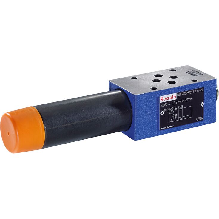
ZDR6DA2-4X/150Y
Rexroth
R900410849
叠加板式阀。
油口布置符合ISO 4401-03-02-0-05,可带或不带定位孔。
四种压力等级。
四种调节方式:旋钮;带六角及保护帽的调节套;带刻度的可锁定旋钮;带刻度旋钮。
在A、B或P通道中减压。
可选单向阀,仅适用于“A”型。
防腐蚀结构。
ZDR型阀是带二次回路限压功能的叠加板式直动减压阀,用于降低系统压力。
减压阀主要包括阀体(1)、控制阀芯(2)、压缩弹簧(3)、调节装置(4)以及可选单向阀。
通过调节装置(4)设定二次压力。
“A”版本。
阀在初始位置开启,液压油可由A➀无阻流向A➀。同时,A➀通道压力经控制管路(5)作用于压缩弹簧(3)对侧的活塞面积。压力超过弹簧(3)设定值时,控制阀芯(2)克服弹簧移至控制位置,使A➀通道压力保持设定值。
控制信号和先导油通过控制油路(5)从通道 A➁ 内部引入。
若执行器受到外力,导致通道 A➀ 中的压力继续升高,压力会推动控制阀芯(2)进一步克服压缩弹簧(3)的作用而移动。
由此,通道 A➀ 经控制阀芯(2)上的控制边(9)及阀体(1)与油箱连通。足量液压油排入油箱,使压力不再继续升高。
弹簧腔(7)的泄漏油始终经孔(6)及T(Y)通道外部排出。
压力表接口(8)可用于检查阀的二次压力。
对于“A”型,可通过单向阀实现自由回流。
“P”及“B”版本。
对于“P”型,在通道 P➀ 中减压。控制信号和先导油均由通道 P➀ 内部引入。
对于“B”型,在通道 P➀ 中减压,但先导油取自通道 B。
注意:
若换向阀处于 P 至 A 的阀位,通道 B 的压力不得超过设定的二次压力,否则通道 A 中会发生减压。
① | component side |
② | plate side |
01 | 02 | 03 | 04 | 05 | 06 | 07 | 08 | 09 | 10 | 11 | 12 | 13 | 14 | ||
Z | DR | 6 | D | – | 4X | / | Y | * |
01 | Sandwich plate valve | Z |
02 | Pressure reducing valve | DR |
03 | Size 6 | 6 |
04 | Direct operated | D |
05 | Pressure reduction in channel A➁ | A |
Pressure reduction in channel B➁ | B | |
Pressure reduction in channel P➁ | P | |
Adjustment type | ||
06 | Rotary knob | 1 |
Sleeve with hexagon and protective cap ("J3" version without protective cap) | 2 | |
Lockable rotary knob with scale | 3 1) | |
Rotary knob with scale | 7 | |
07 | Component series 40 … 49 (40 … 49: unchanged installation and mounting dimensions) | 4X |
08 | Secondary pressure up to 25 bar | 25 |
Secondary pressure up to 75 bar | 75 | |
Secondary pressure up to 150 bar | 150 | |
Secondary pressure 210 bar | 210 | |
Secondary pressure up to 315 bar (only version "B", "P", and "2") | 315 | |
09 | Internal pilot oil supply, external pilot oil return | Y |
10 | With check valve (only version "A") | no code |
Without check valve | M | |
Corrosion resistance | ||
11 | None | no code |
Improved corrosion protection (240 h salt spray test according to EN ISO 9227) | J3 | |
Seal material | ||
12 | NBR seals | no code |
FKM seals | V | |
Observe compatibility of seals with hydraulic fluid used. | ||
13 | Without locating hole | no code |
With locating hole | /60 2) | |
With locating hole and locking pin ISO 8752-3x8-St | /62 | |
13 | Further details in the plain text | * |
| 1) | H-Key with material no. R900008158 is included in the scope of delivery. |
| 2) | Locking pin ISO 8752-3x8-St, material no. R900005694 (separate order) |
Notes:
For valve types for use in potentially explosive areas, refer to data sheet 07011.
Preferred types and standard units are contained in the EPS (standard price list).
Size | 6 | ||
Weight (approx.) | kg | 1.2 | |
Installation position | any | ||
Ambient temperature range | NBR seals | °C | -30 … +80 |
FKM seal | °C | -20 … +80 | |
MTTFD values according to EN ISO 13849 1) | Years | 150 … 1200 | |
| 1) | For further details, see data sheet 08012 |
Size | 6 | ||
Maximum operating pressure (Input) | Version "B", "P" | bar | 350 |
Version "A" | bar | 315 | |
Maximum secondary pressure 1) | Outlet | bar | 25 75 150 210 315 |
Maximum counter pressure | Port T (Y) | bar | 160 |
Maximum flow | l/min | 50 | |
Hydraulic fluid | see table | ||
Hydraulic fluid temperature range | NBR seals | °C | -30 … +80 |
FKM seal | °C | -20 … +80 | |
Viscosity range | mm²/s | 10 … 800 | |
Maximum admissible degree of contamination of the hydraulic fluid 2) | Class 20/18/15 according to ISO 4406 (c) | ||
| 1) | 315 bar only with version “B” and “P” |
| 2) | The cleanliness classes specified for the components must be adhered to in hydraulic systems. Effective filtration prevents faults and simultaneously increases the life cycle of the components. For the selection of the filters, see www.boschrexroth.com/filter. |
Hydraulic fluid | Classification | Suitable sealing materials | Standards | Data sheet | |
Mineral oils | HL, HLP, HLPD | NBR, FKM | DIN 51524 | 90220 | |
Bio-degradable 1) | Insoluble in water | HETG | NBR, FKM | ISO 15380 | 90221 |
HEES | FKM | ||||
Soluble in water | HEPG | FKM | ISO 15380 | ||
Flame-resistant | Water-free | HFDU (glycol base) | FKM | ISO 12922 | 90222 |
HFDU (ester base) 1) | FKM | ||||
HFDR 1) | FKM | ||||
Containing water 1) | HFC (Fuchs Hydrotherm 46M, Petrofer Ultra Safe 620) | NBR | ISO 12922 | 90223 | |
Important information on hydraulic fluids:
| |||||
| 1) | In connection with the corrosion-protected version “J3”, small amounts of dissolved zinc may get into the hydraulic system. |
Dimensions in mm
| |
Required surface quality of the valve contact surface |
➀ | component side – porting pattern according to ISO 4401-03-02-0-05 (with or without locating hole); (with locating hole Ø3 x 5 mm deep) |
➁ | plate side – Porting pattern according to ISO 4401-03-02-0-05 (with or without locating hole); (with locating hole Ø3 x 5 mm deep for locking pin ISO 8752-3x8-St, material no. R900005694, separate order) |
1 | Name plate |
2 | Adjustment type "1" |
3 | Adjustment type "2" |
4 | Adjustment type "3" |
5 | Adjustment type "7" |
6 | Space required to remove the key |
7 | Valve mounting bores |
8 | Lock nut SW24 |
9 | Hexagon SW10 |
10 | Identical seal rings for ports A, B, P, T (Y) |
11 | Pressure gauge connection G1/4; 12 mm deep; internal hexagon SW6 |
Valve mounting screw (separate order)
4 hexagon socket head cap screws ISO 4762-M5-10.9
Notices:
Length and tightening torque of the valve mounting screws must be calculated according to the components mounted under and over the sandwich plate valve.
The dimensions are nominal dimensions which are subject to tolerances.