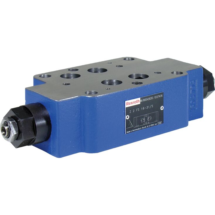
Z2FS16-8-3X/S2
Rexroth
R900457256
叠加板式阀。
油口布置符合ISO 4401-07-07-0-05。
限制两个执行器油口的流量。
调节方式:内六角调节螺杆。
进油节流或回油节流。
Z2FS型阀是叠加板式单向节流阀,用于限制一个或两个执行器油口的流量。
两个对称布置的单向节流阀,通过可调节流阀芯限制一个方向的流量,并允许反向自由回流。
采用进油节流时,液压油从通道 A➀ 经节流点(1)流向执行器 A➁。可通过螺杆(3)轴向调节节流阀芯(2.1),以改变节流点(1)的开度。
同时,通道 A➀ 中的液压油经孔(4)导向活塞侧(5)。
作用压力及弹簧力使节流阀芯(2.1)保持在节流位置。
执行器B➁的回油推动节流阀芯(2.2),使其作为单向阀允许无阻流动。根据S或S2版本,节流作用可发生在进油或回油方向。
流量限制
为调节执行器速度,节流单向阀安装在换向阀与底板之间。
进油节流
➀ | component side |
➁ | plate side |
01 | 02 | 03 | 04 | 05 | 06 | 07 | 08 | 09 | 10 | 11 | ||
Z | 2 | FS | 16 | 8 | – | 3X | / | * |
01 | Sandwich plate valve | Z |
Number of functions | ||
02 | 2 (throttling in channel A and/or B) | 2 |
03 | Throttle check valve | FS |
04 | Size 16 | 16 |
Functions in | ||
05 | Channel A | A |
Channel B | B | |
Channel A and B | – | |
Adjustment type | ||
06 | Spindle with internal hexagon | 8 |
07 | Component series 30 ... 39 (30 ... 39: unchanged installation and connection dimensions) | 3X |
Supply throttling / discharge throttling | ||
08 | Supply throttling on side A ("…A8–3X/S") | S |
Supply throttling on side B ("…B8–3X/S") | ||
Supply throttling on side A and B ("…–8–3X/S") | ||
Discharge throttling on side A ("…A8–3X/S2") | S2 | |
Discharge throttling on side B ("…B8–3X/S2") | ||
Discharge throttling on side A and B ("…–8–3X/S2") | ||
Corrosion resistance (outside) | ||
09 | None (valve housing primed) (standard) | no code |
Improved corrosion protection (240 h salt spray test according to EN ISO 9227) | J3 | |
Seal material | ||
10 | NBR seals | no code |
FKM seals | V | |
Observe compatibility of seals with hydraulic fluid used. (Other seals upon request) | ||
11 | Further details in the plain text | * |
Preferred types and standard units are contained in the EPS (standard price list).
Size | 16 | ||
Weight (approx.) | kg | 4.7 | |
Installation position | any | ||
Ambient temperature range | NBR seals | °C | -30 … +80 |
FKM seals | °C | -20 … +80 | |
Size | 16 | ||
Maximum operating pressure | bar | 350 | |
Maximum flow | l/min | 250 | |
Hydraulic fluid | see table | ||
Hydraulic fluid temperature range | NBR seals | °C | -30 … +80 |
FKM seals | °C | -20 … +80 | |
Viscosity range | mm²/s | 2.8 … 380 | |
Maximum admissible degree of contamination of the hydraulic fluid 1) | Class 20/18/15 according to ISO 4406 (c) | ||
| 1) | The cleanliness classes specified for the components must be adhered to in hydraulic systems. Effective filtration prevents faults and simultaneously increases the life cycle of the components. For the selection of the filters, see www.boschrexroth.com/filter. |
Hydraulic fluid | Classification | Suitable sealing materials | Standards | Data sheet | |
Mineral oils | HL, HLP | NBR, FKM | DIN 51524 | 90220 | |
Bio-degradable | Insoluble in water | HEES 2) | FKM |
ISO 15380 | 90221 |
Soluble in water | HEPG 2) | FKM |
ISO 15380 | ||
Containing water | Containing water | HFC (Fuchs Hydrotherm 46M, Petrofer Ultra Safe 620) 2) |
NBR | ISO 12922 | upon request |
Important information on hydraulic fluids:
Flame-resistant – containing water:
| |||||
| 2) Not for version "J3" |
Dimensions in mm
Dimensions in mm
1 | Name plate |
2 | Adjustment type "8“ Spindle for changing the flow cross-section (internal hexagon SW6)
|
3 | Through holes for valve mounting |
4 | Identical seal rings for ports A, B, P, T |
5 | Identical seal rings for ports X, Y, L |
6 | Locking pin (included in the scope of delivery) |
7 | Hexagon SW19, tightening torque MA see table |
8 | Porting pattern according to ISO 4401-07-07-0-05 |
9.1 | Plug screw with version "B" |
9.2 | Plug screw with version "A" |
Version “Corrosion resistance” | L1 | L2 | L3 | L4 | L5 | L6 | Pos. 7 MA in Nm ±10 % |
mm | mm | mm | mm | mm | mm | Nm | |
| "no code" | 224 | 248 | 224 | 248 | 246 | 294 | 25 |
| „J3“ | 227 | 251 | 227 | 251 | 252 | 300 | 33 |
Valve mounting screws (separate order)
metric
4 hexagon socket head cap screws ISO 4762 - M10 - 10.9-flZn-240h-L
2 hexagon socket head cap screws ISO 4762 - M6 - 10.9-flZn-240h-L
UNC
4 hexagon socket head cap screws 3/8-16 UNC
2 hexagon socket head cap screws 1/4-20 UNC
Notice:
Length and tightening torque of the valve mounting screws must be calculated according to the components mounted under and over the sandwich plate valve.