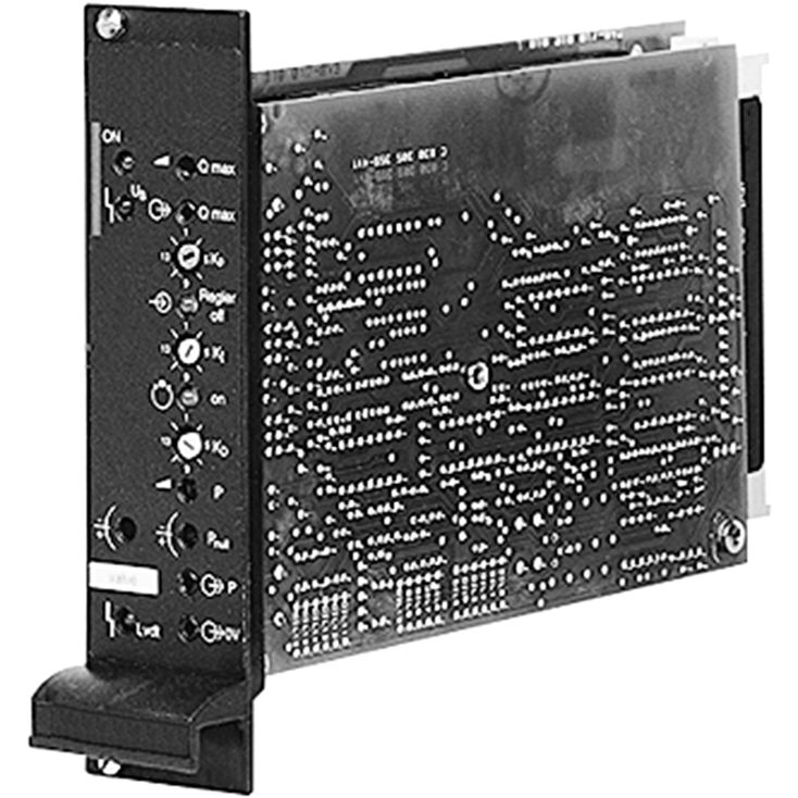
VT-VARAP1-527-20/V0
Rexroth
0811405152
适用于控制直动式及先导式高响应阀。
带附加电子装置(子卡)的放大器。
欧洲卡式模拟放大器,适于安装在19英寸机架中。
具有PID特性的阀位置控制。
通过外部压力传感器进行压力控制。
受控功率输出级。
使能输入。
输出具备短路保护。
可调项目:阀的零点。
实际值信号电缆及压力传感器断线检测。
快速励磁与快速消磁,使动作时间缩短。
外部控制器切断。
适用于1…6 V、0…10 V、4…20 mA压力传感器,参见样本30271。
01 | 02 | 03 | 04 | 05 | 06 | 07 | 08 | 09 | 10 | 11 | ||||
VT- | V | A | R | A | P | 1 | – | – | 2X | / | V0 | / |
01 | VT- | |
02 | V | |
Hydraulic component (control) | ||
03 | Axis control | A |
Valve type | ||
04 | High-response valve | R |
Control | ||
05 | Analog | A |
Function | ||
06 | p/Q control | P |
Output stages | ||
07 | 1 output stage | 1 |
Serial number for types | ||
08 | 2.7 A solenoid | 527 |
3.7 A solenoid | 537 | |
09 | Component series 20 ... 29 (20 ... 29: unchanged technical data and pin assignment) | 2X |
Customer version | ||
10 | Catalog version | V0 |
Option | ||
11 | High-response valve size 6/10, direct operated | no code |
p/Q valve size 10, direct operated | 5/3V | |
High-response valve, pilot-operated | 2STV | |
High-response valve, pilot-operated, control line A → X | 3/2V | |
Type / version | VT-VARAP1-527 | VT-VARAP1-537 | |||
Supply voltage | nominal 24 V= battery voltage 21...40 V, rectified alternating voltage Ueff = 21...28 V (single-phase, full-wave rectifier) | ||||
Smoothing capacitor, separately | Recommendation: Capacitor module VT 11110 (see data sheet 30750) (only necessary if the ripple of UB >10 %) | ||||
Valve solenoid, max. | A | 2.7 | 3.7 | ||
Current consumption, max. 1) | A | 1.7 | 2.7 | ||
Power consumption (typical) | W | 37 | 55 | ||
Input signal (command value) | b20: 0...±10 V – differential amplifier z20: 0...±10 V – differential amplifier (Ri= 100 kΩ) | ||||
Input signal (command value p) | z12: 0...+10 V – differential amplifier z10: 0 V – differential amplifier | ||||
Actual value from the pressure sensor | z14: 4...20 mA – current input b16: 0...+10 V/1...+6 V – voltage input b18: 0 V – reference | ||||
Pressure controller OFF | b10: 6...40 V= | ||||
External enquiry pressure controller active | z24: 24 V/0.1 A max. | ||||
Limit frequency | for applications ≤ 30 Hz | ||||
Signal source | Potentiometer 10 kΩ Supply with ±10 V from b32, z32 (10 mA) or external signal source | ||||
Enable output stage | at z16, U= 8.5...40 V, Ri = 100 kΩ LED (green) on front plate lights up | ||||
Sensor supply | z6: +15 V/35 mA, Ri ~ 25 Ω | ||||
Position transducer | Supply | b30: -15 V (25 mA) z30: +15 V (35 mA) | |||
Pilot control valve | Actual value signal | b22: 0...±10 V, RL = 10 kΩ/Ref. b24 | |||
Main stage | Actual value reference | b26: 0...±10 V, RL = 10 kΩ/Ref. b28 | |||
Solenoid output | Clocked current controller | ||||
Imax | A | 2.7 | 3.7 | ||
Cable lengths between amplifier and valve | Solenoid cable | m | 20 | ||
m | 20 … 60 | ||||
Number of wires / line cross-section | Position transducer | 4 x 0.5 mm2 (shielded) | |||
Pressure sensor | 4 x 0.5 mm2 (shielded) | ||||
Special features | Cable break protection for actual value cable Position control with PID behavior Pulsed output stage Fast energization and fast deletion for short actuating times Short-circuit-proof outputs External controller shut-off | ||||
Adjustment | Zero point via trimming potentiometer ±5 % Command value attenuator Q Pressure controller KP, KI and KD Sensitivity pressure load cell Zero point pressure load cell | ||||
LED displays | green | Enable | |||
yellow | Cable break position transducer | ||||
red | Supply voltage (UB too low) | ||||
yellow | Pressure controller OFF | ||||
yellow | Pressure controller working | ||||
both yellow LEDs are flashing | Cable break pressure sensor | ||||
Error message | Cable break actual value | z22: Open collector output to +UB max. 100 mA; no error: +UB | |||
Plug-in connection | Plug to DIN 41612-F32 | ||||
Operating temperature | °C | 0 … +70 | |||
Storage temperature range | °C | -20 … +70 | |||
Weight | m | kg | 0.49 | ||
| 1) | Current consumption may increase with min. UB and extreme cable lengths to the control solenoid |
功率零线 b2 与控制零线 b12、b14 或 z28,必须分别引至中央接地点(星形接地点)。
Dimensions in mm