VT-SWMAK-1-1X/V0/0
Rexroth
R900217318
电压差分输入。
灵敏度、阶跃高度及零点可调。
使能输入。
操纵信号输出。
阶跃功能可快速越过换向阀的遮盖区。
工作电压极性反接保护。
01 | Analog command value module | VT-SWMAK-1 |
02 | Component series 10 ... 19 (10 ... 19: unchanged installation and connection dimensions) | 1X |
03 | Version: standard | V0 |
04 | Option: standard | 0 |
05 | Further details in the plain text | * |
01 | 02 | 03 | 04 | 05 | |||
VT-SWMAK-1 | ‒ | 1X | / | V0 | / | 0 | * |
Component series | 1X | |
Type of electronics | Analog | |
Design | Modul |
Operating voltage | Nominal | UB | V | 24 |
Lower limit value | UB(t)min | V | 18 | |
Upper limit value | UB(t)max | V | 35 | |
Power consumption | PS | VA | 1.2 | |
Current consumption | max. | Imax | A | 0.05 |
Fuse | Electronic fuse protection | |||
Command value | Voltage | Differential input 1) | U | V | 0 … ±10 |
Input resistance | R | kΩ | 100 |
| 1) | Joint reference potential with actuating signal output |
Enable | On (active) | UF | V | 8.5 ... UB |
Off (inactive) | UF | V | 0 ... 6.5 |
Voltage | Number and designation | 1 (control output) | ||
Voltage | U | V | 0 … ±10 | |
Setting range | Zero point calibration | % | ± 10 | |
Setting range 1) | Amplitude attenuator for command value | % | 0 ... 110 | |
Setting range 2) | Step-change height | % | 0 ... 50 |
| 1) | Applies to a step level setting of 0 %, separately adjustable for positive and negative signals. |
| 2) | Step level reached at Ucommand = 2 %, separately adjustable for positive and negative signals. |
Command value 1) | "w" | Uw | V | 0 ... ±10 |
| 1) | ±10 V ≙ ±100 % |
LED display | Green 1 | power | |
Green 2 | Enable |
Anschlussart | 6 screw terminals | ||
Mounting type | Top hat rail TH 35-7.5 according to EN 60715 | ||
Protection class according to DIN EN 60529 | IP 20 | ||
Ambient temperature range | ϑ | °C | 0 … 50 |
Storage temperature range | ϑ | °C | -25 … 85 |
Weight | m | kg | 0.08 |
Dimensions in mm
Dimensions in mm
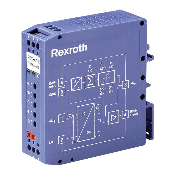
指令值模块以24 V直流电压运行,电源单元[7]提供内部所需正、负电压。电源单元开始工作后,绿色“power”LED点亮。通过使能输入端口3的信号,可接通或关闭操纵信号。无使能信号时,操纵信号相对于指令值参考地GND为0%。
求和环节 [2] 将通过“Z”电位器调节的偏置量叠加到外部给定的指令值上,从而补偿控制侧的零点偏差,并精确调整液压零点。利用可调特性曲线发生器 [3],可分别设置正、负信号的阶跃量和最大值,使其独立匹配液压系统要求。
电位器“S+”“S–”用于补偿阀的遮盖区,“G+”“G–”用于设定比例伺服阀的最大流量,参见图示、特性曲线及调试说明。
操纵信号与指令值采用同一参考电位。参考电位发生波动时,加法器[4]对操纵信号进行相应修正。