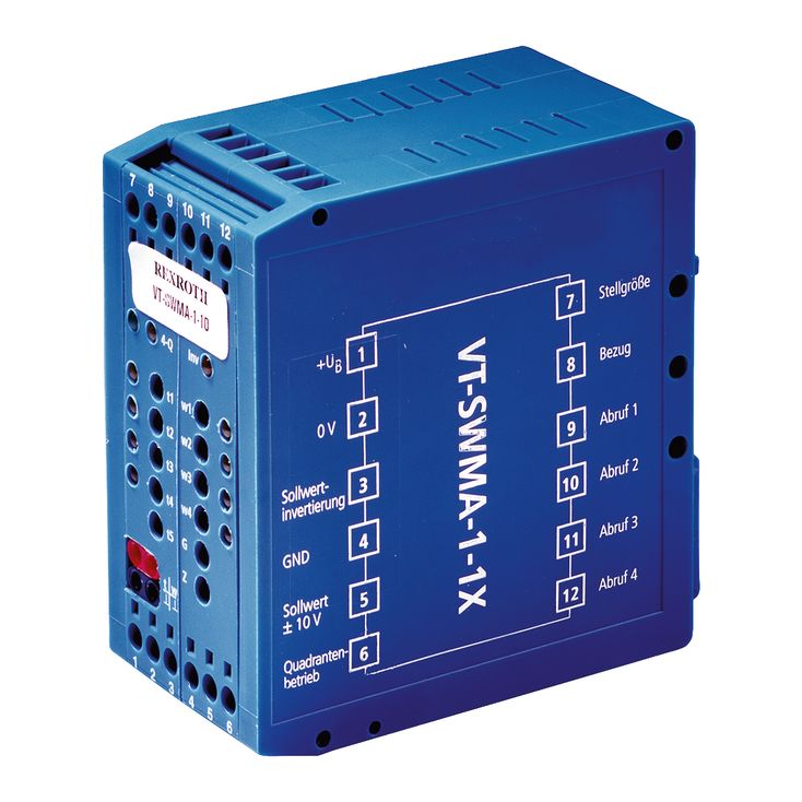
VT-SWMA-1-1X/V0/0
Rexroth
R900942541
可通过数字控制实现简单液压功能。
调节元件:一个零点调节电位器(指令值偏置);一个差分输入指令值衰减电位器;四个指令值预选电位器;五个斜坡时间调节电位器。
LED指示:指令值调用四路、有效斜坡时间四路、象限识别、极性反转及电源状态。
用于指令值与斜坡时间的测量插孔。
差分输入。
指令值与斜坡时间各有四种调用方式。
斜坡发生器带五个斜坡时间及四象限识别。
操纵信号输出。
不抬高零点的电源单元。
不带功率部分。
01 | 02 | 03 | 04 | 05 | |||
VT-SWMA-1 | ‒ | 1X | / | V0 | / | 0 | * |
01 | Analog command value module | VT-SWMA-1 |
02 | Component series 10 ... 19 (10 ... 19: unchanged installation and connection dimensions) | 1X |
03 | Basic version | V0 |
04 | Basic version | 0 |
05 | Further details in the plain text | * |
Component series | 1X | |
Type of electronics | Analog | |
Design | Modul |
Operating voltage | Nominal 1) | UB | VDC | 24 |
Lower limit value | UB(t)min | V | 18 | |
Upper limit value | UB(t)max | V | 35 | |
Power consumption | PS | VA | 12 | |
Current consumption | max. | Imax | A | 0.5 |
Fuse | Thermal overload protection (with restart if the value falls below the temperature threshold) | |||
| 1) | +40 % –10 % |
Command value | Voltage | Differential input with attenuator | Ue | V | 0 … ±10 |
Input resistance | RE | kΩ | > 50 |
Command value call-ups 1 to 4 | Active 1) | U | V | 8.5 ... 35 |
Not active | U | V | 0 ... 6.5 | |
Command value inversion “Inv“ | Active 1) | UInv | V | 8.5 ... 35 |
Not active | UInv | V | 0 ... 6.5 | |
Quadrant operation “4-Q“ | Active 1) | U4-Q | V | 8.5 ... 35 |
Not active | U4-Q | V | 0 ... 6.5 |
| 1) | RE > 50 kΩ |
Voltage | Number and designation | 1 (control output) | ||
Voltage 1) | U | V | 0 … ±10 | |
Voltage | Load resistance | RL | kΩ | >5 |
| 1) | ±6 mA |
Adjustment range | Zero balancing (potentiometer “Z“) | % | ± 10 | |
Amplitude attenuator (potentiometer “G“) | % | 0 to ca. 110 | ||
Command values (potentiometers “w1“ to “w4“) 1) | % | 0 to ca. 110 | ||
Ramp times (potentiometers “t1“ to “t5“) | t | s | 0,02 … 5 |
| 1) | Factory setting: 100 % |
Measuring socket for control variable “w“ 1) | Uw | V | 0 ... ±10 |
Measuring socket for ramp time “t“ | Ut | 0.01 V to +10 V 0.01 V (tmax = ca. 10 s); 10 V (tmin = ca. 10 ms) |
| 1) | 10 V ≙ 100 %; -10 V ≙ –100 % |
Type of connection | 12 screw terminals | ||
Type of mounting | Top hat rail TH 35-7.5 according to EN 60715 | ||
Type of protection according to EN 60529 | IP 20 | ||
Dimensions (W x H x D) | mm | 40 x 79 x 85.5 | |
Permissible operating temperature range | ϑ | °C | 0 … 50 |
Storage temperature range | ϑ | °C | -25 … +85 |
Weight | m | kg | 0.13 |
注意:
关于 EMC(电磁兼容性)、气候和机械应力方面的环境模拟试验详情,请参见 RE 29902-U(环境适应性声明)。
Dimensions in mm
| 1) | Top hat rail TH 35-7.5 according to EN 60715 |
指令值模块卡装于符合EN 60715的帽形导轨,采用螺钉端子接线,以24 V直流电压运行。电源单元[1]提供内部所需正、负电压,开始工作后绿色“power”LED点亮。
内部指令值由差分输入[2]上的外部指令值信号、调用信号及偏置信号生成,偏置信号来自零点电位器“Z”[3]。
通过电位器“G”,即幅值衰减器[4],可将外部指令值信号调节至0%至约110%。
调用信号 w1 至 w4 [5] 也可在 0 % 至 110 % 之间调节。调用信号 w1、w2 为正极性,w3、w4 为负极性。由此可实现……
无需附加电路,即可使液压驱动完成两次正向及两次反向运动。若应用要求同一极性的信号超过两个,可采用指令值反相[6];启用后,例如。
例如,调用3时,调用信号w3也会产生正操纵量。
同一时刻只能执行一个调用。若同时激活多个调用,则调用“1”的优先级最低,调用“4”的优先级最高 [7]。
启用象限识别[8]后,电子装置自动识别操纵量的极性[9]及上升/下降变化[10],并为当前信号状态分配斜坡时间。
Ramp time | Polarity of the control output | Signal changes in direction of… | |||
t1 | + | Maximum value | 0 % | | Maximum value (+) |
t2 | + | 0 % | Maximum value (+) | | 0 % |
t3 | – | Maximum value | 0 % | | Maximum value (–) |
t4 | – | 0 % | Maximum value (–) | | 0 % |
在信号变化期间,与当前斜坡对应的 LED 指示灯保持点亮。
未启用象限识别时,指令值调用w1至w4分别对应独立的斜坡时间t1至t4。
在信号变化期间,与当前斜坡时间对应的 LED 指示灯保持点亮。
如果既未激活象限识别,也未激活指令值调用,则始终采用斜坡时间“t5”。该时间可用于紧急停止等功能,使阀按规定的“t5”斜坡时间关闭。
可在测量插孔“t”[13]检查当前斜坡时间。斜坡时间电位器可调节t1至t4;激活调用信号时,插孔处斜坡时间信号t明确对应其中一个时间。未激活调用或象限识别时,插孔信号对应t5。斜坡时间调节范围使其可重复设定,详见“技术参数”。
斜坡时间调节与测量说明
调节斜坡时间电位器时,建议关闭四象限识别并激活指令值调用。
Value at measuring socket “t" | Ut in V | 5 | 3 | 2 | 1 | 0.5 | 0.3 | 0.2 | 0.1 | 0.05 | 0.03 | 0.02 |
Current ramp time (±20 %) | t in ms | 20 | 33 | 50 | 100 | 200 | 333 | 500 | 1000 | 2000 | 3333 | 5000 |
下述关系成立:
示例:测得 Ut = 5 V
结果为
斜坡发生器输出可在测量插孔“w”[14]检查。下游匹配放大器[15]通过“操纵量”输出[16]为阀提供控制信号。
方括号[]表示框图交叉引用,参见“符号/回路图”。