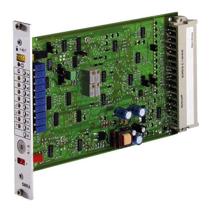
VT-SWKA1-5-1X/V0/0
Rexroth
0811405093
电压及电流差分输入。
四个可调用的指令值输入,以及斜坡时间输入。
数字输入用于使能、斜坡、反相及指令值调用。
电压及电流控制输出。
通过象限识别选择斜坡时间。
工作电压极性反接保护。
可切换测量插孔。
“准备就绪”输出。
通过分别调节阶跃高度及最大值,修正特性曲线。
01 | Analog command value card | VT-SWKA-1 |
02 | Component series 10 ... 19 (10 ... 19: unchanged installation and connection dimensions) | 1X |
03 | Version: standard | V0 |
04 | Option: standard | 0 |
05 | Further details in the plain text | * |
01 | 02 | 03 | 04 | 05 | ||||
VT-SWKA-1 | ‒ | 1X | / | V0 | / | 0 | / |
Component series | 1X | |
Type of electronics | Analog | |
Design | Euro-card |
Operating voltage | Nominal | UB | V | 24 |
Lower limit value | UB(t)min | V | 18 | |
Upper limit value | UB(t)max | V | 35 | |
Power consumption | max. | PS | VA | 7 |
Current consumption | max. | I | A | 0.3 |
Fuse | IS | Thermal overload protection; self-activating after tripping | ||
Command value | Voltage | Differential input | Ue | V | 0 … ±10 |
Differential input resistance | Re | kΩ | > 50 | ||
Potentiometer input 1-4 1) | Ue | V | 0 … ±10 | ||
Input resistance | Re | kΩ | > 100 | ||
Current 2) | Ie | mA | 4 … 20 | ||
Current | Input resistance | RB | Ω | 100 | |
Ramp time | External 3) | Ue | V | 0 … 10 | |
Input resistance | Re | kΩ | 10 | ||
| 1) | Reference potential is M0 |
| 2) | Switchable zero point |
| 3) | Internally raised to +15 V, reference is M0 |
Command value call-ups | On (active) 1) | U | V | 8.5 ... UB |
Off (inactive) | U | V | 0 ... 6.5 | |
Enable | On (active) 1) | U | V | 8.5 ... UB |
Off (inactive) | U | V | 0 ... 6.5 | |
Inverter | On (active) 1) | U | V | 8.5 ... UB |
Off (inactive) | U | V | 0 ... 6.5 | |
Ramp call-ups | On (active) 1) | U | V | 8.5 ... UB |
Off (inactive) | U | V | 0 ... 6.5 | |
4-quadrant operation | On (active) 1) | U | V | 8.5 ... UB |
Off (inactive) | U | V | 0 ... 6.5 |
| 1) | RE > 100 kΩ |
Voltage | Number and designation | 1 (control output) | ||
Voltage 1) | U | V | 0 … ±10 | |
Current | Number and designation | 1 (control output) | ||
Current 2) | U | mA | 4 … 20 A | |
Measurement signal | U | V | 0 ... ±10 ±2% (Imax = 2 mA) | |
| 1) | Imax = 2 mA |
| 2) | RBmax = 500 Ω, switchable zero point |
Ready for operation | On (active) 1) | U | V | 16 ... UB |
Off (inactive) | U | V | 0 ... 1 | |
Ramp | timeout 1) | U | V | 16 ... UB |
no timeout | U | V | 0 ... 1 |
| 1) | Imax = 50 mA, Ri = 10 kΩ |
Setting range | Zero point calibration | % | ± 30 | |
Setting range | Command value attenuator potentiometer input | % | 0 ... 110 | |
Setting range 1) | Amplitude attenuator for command value | % | 0 ... 110 | |
Setting range 1 | Ramp time up/down | t | s | 0,02 … 5 |
Setting range 2 | Ramp time up/down | t | s | 0,2 … 50 |
Setting range 2) | Step-change height | % | 0 ... 50 |
| 1) | Applies to a step level setting of 0% |
| 2) | Step level reached at Ucommand = 2 %, separately adjustable for positive and negative signals. |
Switchable | "v" | U | V | 0 ... ±10 ±2% (Imax = 2 mA) |
LED display | Green 1 | Ready for operation | |
Yellow 1 | Enable | ||
Yellow 2 | Inverter | ||
Yellow 4 | 4-quadrant operation |
Reference voltage | Potentiometer supply | U | V | ±10 ±2% (Imax = 25 mA, short-circuit-proof) |
Anschlussart | 48-pole male multipoint connector, DIN 41612, design F | |||
Ambient temperature range | ϑ | °C | 0 … 50 | |
Storage temperature range | ϑ | °C | -25 … 85 | |
Weight | m | kg | 0.15 | |
Dimensions in mm
Dimensions in mm
指令值卡采用欧洲卡式印制电路板,适于机架安装。内部电源单元[1]提供所需正、负电源电压。电源单元工作正常且未检测到故障时,前面板绿色LED点亮,并置位“准备就绪”信号。
电流与电压输入之间无需切换,两个输入始终可用,参见端子分配。输入信号在内部归一化后相加。通过跳线J5可切换电流输入的零点及量程。
可调用“w1”至“w4”四个指令值信号。外部指令值电压(指令值 1 至 4)可直接由稳压输出 +10 V、–10 V 给定,也可通过外部电位器给定。若指令值输入直接连接稳压电压,则通过“w1”至“w4”电位器设置指令值;使用外部电位器时,内部电位器起衰减器或限幅器作用。
同一时刻只能执行一个调用。若同时激活多个调用,则调用“1”的优先级最低,调用“4”的优先级最高。
当前有效的调用由前面板黄色LED指示。
由输入信号、指令值调用及零点偏置信号生成的内部指令值,可通过外部信号或跳线J1反相。连接外部反相信号时,前面板“–1”LED会指示该状态。
使能功能接通或关闭斜坡发生器的输入信号。使能切换时,无论指令值如何,控制输出均按所设斜坡时间变化,避免受控阀突然开启或关闭。出现故障信号时,斜坡发生器输入也置为0%。前面板LED指示使能信号状态。
斜坡发生器限制控制输出的变化斜率。下游阶跃功能及幅值衰减器不会延长或缩短斜坡时间。
通过跳线J2,可将斜坡时间设为最小值,小于2 ms,即关闭斜坡。
通过外部电位器可延长内部设定的斜坡时间,并在测量插孔检查设定。发生断线时,自动采用内部默认设置。
斜坡时间设置与测量说明:
Value at measuring socket "v" | U/V | 5 | 3 | 2 | 1 | 0.5 | 0.3 | 0.2 | 0.1 | 0.05 | 0.03 | 0.02 |
Current ramp time (±20 %) | t/ms | 20 | 33 | 50 | 100 | 200 | 333 | 500 | 1000 | 2000 | 3333 | 5000 |
改变跳线 J3 的连接位置,可使上述斜坡时间增加至十倍。
“ramp ready”斜坡就绪状态信号表示控制输出已达到所需终值。利用该24 V输出,上级顺序控制可更方便地与阀功能或受控液压功能同步。
利用可调特性曲线发生器,可分别设置正、负信号的阶跃高度及最大值,以适应液压要求。特性曲线通过零点时不是阶跃变化,而是线性变化。
电流及电压控制输出被限制在约额定范围的±110%。
系统监测内部工作电压及电压输出;连接跳线J7(1-2)时,还对电流输出进行断线检测。无故障时,绿色“准备就绪”LED点亮,准备就绪输出切换至24 V工作电压。
前面板设有测量插座,用于检查指令值调用、斜坡时间的设置以及其他内部信号。测量点可通过同样位于前面板上的测量点选择开关进行选择。测量插座的信号也连接至多点插头的 b26 端子。
方括号[]表示框图中的对应位置。