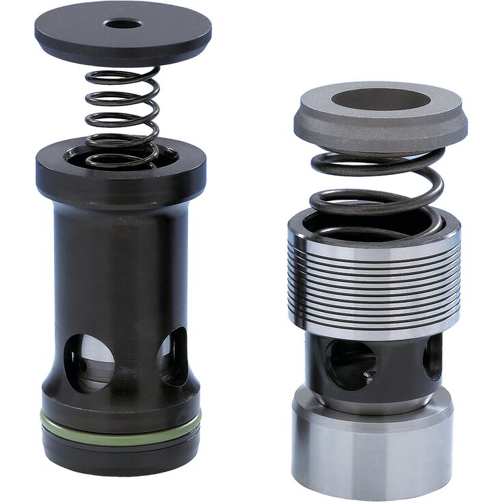
M-SR 30 KE05-1X/
Rexroth
R900344919
适于集成块安装。
• 角式阀结构。
• 直通式阀结构。
单向无泄漏封闭。
可选不同开启压力。
01 | 02 | 03 | 04 | 05 | 06 | 07 | 08 | ||
M-SR | – | 1X | / | * |
01 | Check valve, cartridge design | M-SR |
Size | ||
02 | Size 6 (not version "KE") | 6 |
Size 8 | 8 | |
Size 10 | 10 | |
Size 15 | 15 | |
Size 20 | 20 | |
Size 25 | 25 | |
Size 30 | 30 | |
Unit design | ||
03 | Angle valve | KE |
Straight-through valve | KD | |
Cracking pressure | ||
04 | 0 bar, without spring (not version "KD") | 00 |
0,2 bar | 02 | |
0.5 bar (standard) | 05 | |
1,5 bar | 15 | |
3,0 bar | 30 | |
5,0 bar | 50 | |
05 | Component series 10 ... 19 (10 ... 19: unchanged installation and connection dimensions) | 1X |
Orifice in channel B (version "KD" only) | ||
06 | Without orifice | no code |
Core hole M4 | B00 | |
Nozzle Ø 1.0 mm | B10 | |
Nozzle Ø 1.2 mm | B12 | |
Seal material (observe compatibility of seals with hydraulic fluid used, see "Technical data") (version "KE" only) | ||
07 | NBR seals | no code |
FKM seals | V | |
08 | Further details in the plain text | * |
Size | 6 | 8 | 10 | 15 | 20 | 25 | 30 | ||
Weight | Angle valve "KE" | kg | - | 0.03 | 0.05 | 0.08 | 0.14 | 0.32 | 0.47 |
Straight-through valve "KD" | kg | 0.05 | 0.1 | 0.2 | 0.25 | 0.3 | |||
Installation position | any | ||||||||
Ambient temperature range | NBR seals | °C | -20 … +80 | ||||||
FKM seals | °C | -20 … +80 | |||||||
MTTFD values according to EN ISO 13849 1) | 150 Years | ||||||||
| 1) | For further details, see data sheet 08012 and 90294 |
Size | 6 | 8 | 10 | 15 | 20 | 25 | 30 | ||
Maximum operating pressure | bar | 420 | |||||||
Cracking pressure | See characteristic curves | ||||||||
Maximum flow | l/min | 15 | 35 | 50 | 120 | 200 | 300 | 400 | |
Hydraulic fluid | see table "Hydraulic fluid" | ||||||||
Hydraulic fluid temperature range | NBR seals | °C | -30 … +80 | ||||||
FKM seals | °C | -20 … +80 | |||||||
Viscosity range | mm²/s | 2.8 … 500 | |||||||
Maximum admissible degree of contamination of the hydraulic fluid, cleanliness class according to ISO 4406 (c) 1) | Class 20/18/15 | ||||||||
| 1) | The cleanliness classes specified for the components must be adhered to in hydraulic systems. Effective filtration prevents faults and simultaneously increases the life cycle of the components. For the selection of the filters, see www.boschrexroth.com/filter. |
Hydraulic fluid | Classification | Suitable sealing materials | Standards | Data sheet | |
Mineral oils | HL, HLP | NBR, FKM | DIN 51524 | 90220 | |
Bio-degradable | Insoluble in water | HETG | FKM | ISO 15380 | 90221 |
HEES | FKM | ||||
Soluble in water | HEPG | FKM | ISO 15380 | ||
Flame-resistant | Water-free | HFDU (glycol base) | FKM | ISO 12922 | 90222 |
HFDU (ester base) | FKM | ||||
Containing water | HFC (Fuchs Hydrotherm 46M, Petrofer Ultra Safe 620) | NBR | ISO 12922 | 90223 | |
Important information on hydraulic fluids:
| |||||
Dimensions in mm
Dimensions in mm
| 1) | For dimensions, see installation bores |
NG | L-0,1 |
mm | |
| 6 | - |
| 8 | 36.3 |
| 10 | 39.3 |
| 15 | 45.8 |
| 20 | 55.3 |
| 25 | 74.3 |
| 30 | 83.3 |
1 | Plug screws, separate order, see "Accessories" |
2 | Seat with -60 °C shrink-fitted |
3 | Poppet stroke |
Dimensions in mm
| 1) | Dimensions for countersinking the screw head. For lower installation of the installation kit, dimension T7 has to be extended accordingly. |
| 2) | Depth of fit |
| 3) | Pipe thread "G" according to ISO 228/1 |
1 | Range for outlet bore |
NG | pN | ØD1 | ØD2 | D3 | ØD4H8 | ØD5 | ØD6H7 | T1 | T2 | T3 | T4 | T5 | T6 | T7 | X | Z | ||
bar | mm | mm | mm | mm | mm | mm | mm | mm | mm | mm | mm | mm | mm | mm | mm | |||
| 8 | 420 | 23 | 17.1 | G3/8 | 14 | 8 | 13 | 48.5 | + 0.1 | 47.5 | 38.5 | 20 | 15 | 12 | 6 | + 0.5 | 18 | 0.05 |
| 10 | 420 | 28 | 21.4 | G1/2 | 18 | 10 | 17 | 53.5 | + 0.1 | 52.5 | 43.5 | 24 | 18 | 14 | 6 | + 0.5 | 19 | 0.05 |
| 15 | 420 | 33 | 26.8 | G3/4 | 24 | 15 | 22 | 62 | + 0.1 | 60.5 | 50 | 26 | 20.5 | 16 | 6 | + 0.5 | 24 | 0.05 |
| 20 | 420 | 41 | 33.8 | G1 | 30 | 20 | 28 | 71.5 | + 0.1 | 70 | 56.5 | 26 | 20.5 | 16 | 7 | + 0.5 | 30 | 0.05 |
| 25 | 250 | 51 | 42.5 | G1 1/4 | 38 | 25 | 36 | 90.5 | + 0.1 | 88 | 72.5 | 28 | 22 | 16 | 7 | + 0.5 | 43 | 0.1 |
| 30 | 250 | 56 | 48.5 | G1 1/2 | 44 | 30 | 42 | 99.5 | + 0.1 | 96.5 | 79.5 | 31 | 22 | 16 | 7 | + 0.5 | 48 | 0.1 |
Notice:
Plug screws, separate order, see "Accessories"
Oiling of plug screws prior to installation is recommended.
Dimensions in mm
| 1) | Dimensions for countersinking the screw head. For lower installation of the installation kit, dimension T7 has to be extended accordingly. |
| 2) | Depth of fit |
| 3) | Metric ISO fine thread according to DIN 13 |
1 | Range for outlet bore |
NG | pN | ØD1 | ØD2H8 | D3 | ØD4H8 | ØD5 | ØD6H7 | T1 | T2 | T3 | T4 | T5 | T6 | T7 | T8 | X | ||||
bar | mm | mm | mm | mm | mm | mm | mm | mm | mm | mm | mm | mm | mm | mm | mm | mm | mm | |||
| 25 | 315 | 56 | + 0.5 | 44 | M42 x 1,5 | 38 | 25 | 36 | 106.5 | + 0.1 | 104 | 88.5 | 45 | 39 | 33 | 5 | + 0.5 | 12 | + 0.2 | 43 |
| 30 | 315 | 62 | + 0.5 | 50 | M48 x 1,5 | 44 | 30 | 42 | 115.5 | + 0.1 | 112.5 | 95.5 | 48 | 39 | 33 | 5 | + 0.5 | 12 | + 0.2 | 48 |
Notice:
Plug screws, separate order, see "Accessories"
To be replaced in case of maintenance.
Dimensions in mm
| 1) | Dimensions for countersinking the screw head. For lower installation of the installation kit, dimension T7 has to be extended accordingly. |
| 2) | Depth of fit |
| 3) | Metric ISO fine thread according to DIN 13 |
1 | Range for outlet bore |
NG | pN | ØD1 | ØD2H8 | D3 | ØD4H8 | ØD5 | ØD6H7 | ØD7 | ØD8 | T1 | T2 | T3 | T4 | T5 | T6 | T7 | T8 | X | ||||
bar | mm | mm | mm | mm | mm | mm | mm | mm | mm | mm | mm | mm | mm | mm | mm | mm | mm | mm | mm | |||
| 25 | 420 | 51 | + 0.5 | 44 | M42 x 2 | 38 | 25 | 36 | 37.58 | 35.58 | 101.5 | + 0.1 | 100 | 83.5 | 40 | 34 | 27 | 6 | + 0.5 | 7.8 | + 0.2 | 43 |
| 30 | 420 | 61 | + 0.5 | 50 | M48 x 2 | 44 | 30 | 42 | 43.58 | 41.58 | 110.5 | + 0.1 | 108.5 | 90.5 | 43 | 34 | 27 | 6 | + 0.5 | 7.8 | + 0.2 | 48 |
Notice:
Plug screws, separate order, see "Accessories" Oiling of plug screws prior to installation is recommended.
From an operating pressure larger 350 bar, the plug screw has to be glued by means of Loctite 243 over the complete thread circumference.
Dimensions in mm
NG | ØD1H7 | ØD3H8 | D4 1) | ØD5 | D4 2) | ØD5 | ØD6 | T1 | T2 3) | T3 | T4 3) | T5 | T6 | Z | Poppet stroke | |||
mm | mm | mm 1) | mm | mm 2) | mm | mm | mm | mm | mm | mm | mm | mm | mm | mm | mm | |||
| 6 | 10 | 11 | G1/4 | 13.6 | ± 0.1 | M14 x 1,5 | 14.4 | ± 0.1 | 25 | 29.8 | - 0.1 | 27.8 | 21.8 | 19 | 12 | 16 | 0.1 | 4 |
| 8 | 13 | 14 | G3/8 | 17.1 | ± 0.1 | M18 x 1,5 | 18.4 | ± 0.1 | 28 | 32.8 | - 0.1 | 30.8 | 22.8 | 18 | 12 | 16 | 0.1 | 4 |
| 10 | 17 | 18 | G1/2 | 21.4 | ± 0.1 | M22 x 1.5 | 22.4 | ± 0.1 | 34 | 38.8 | - 0.1 | 36.8 | 28.8 | 21 | 14 | 19 | 0.1 | 4 |
| 15 | 22 | 24 | G3/4 | 26.8 | ± 0.1 | M27 x 2 | 27.4 | ± 0.1 | 42 | 48.4 | - 0.1 | 46.4 | 36.4 | 27 | 16 | 21 | 0.2 | 5 |
| 20 | 28 | 30 | G1 | 33.8 | ± 0.1 | M33 x 2 | 33.5 | ± 0.1 | 47 | 59 | - 0.1 | 57 | 44 | 29 | 18 | 24 | 0.2 | 5 |
| 25 | 36 | 38 | G1 1/4 | 42.5 | ± 0.1 | M42 x 2 | 42.5 | ± 0.1 | 58 | 73 | - 0.1 | 71 | 55 | 39 | 20 | 26 | 0.2 | 7 |
| 30 | 42 | 44 | G1 1/2 | 48.5 | ± 0.1 | M48 x 2 | 48.5 | ± 0.1 | 65 | 83 | - 0.1 | 81 | 63 | 42 | 22 | 28 | 0.2 | 7 |
| 1) | Pipe thread "G" according to ISO 228/1 |
| 2) | Metric ISO fine thread according to DIN 13 |
| 3) | Depth of fit |
规格 8
规格 10
规格 15
规格20。
规格25。
规格30。
规格6。
规格 8
规格 10
规格 15
规格20。
规格25。
规格30。