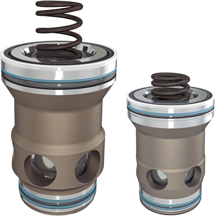
LC 25 B20E7X
Rexroth
R900912604
阀锥可带或不带阻尼头。
两种面积比。
六种不同的开启压力。
二通插装阀专为紧凑式集成块结构设计。带 A、B 接口的主阀部分安装在控制块内符合 ISO 7368 的标准安装孔中,并用盖板封闭。在大多数情况下,盖板还用于连接主阀的控制侧与先导控制阀。
通过相应先导控制阀控制,主阀部分可用于压力、换向、节流功能,或这些功能的组合。根据执行器各流路的不同流量选择合适规格,可获得特别高效的解决方案。将同一主阀组件用于多种功能,也具有很好的经济性。
二通插装阀通常由控制盖板(1)和插装组件(2)组成。控制盖板内设控制油孔,并可根据所需整体功能选配行程限制、液控座阀式换向阀或梭阀。此外,盖板上还可安装电控滑阀式或座阀式换向阀。插装组件包括衬套(3)、环(4,仅适用于 NG32 及以下)、阀芯(5)、可选的带阻尼锥头结构(6)或不带阻尼锥头结构(7),以及关闭弹簧(8)。
二通插装阀的功能取决于压力,涉及A1、A2、A3三个关键受压面积。阀座面积A1作为100%。不同版本通过台阶形成的环形面积A2为A1的7%或50%,面积比A1:A2分别为14.3:1或2:1。面积A3等于A1与A2之和,因此分别为基准阀座面积A1的107%或150%。
一般适用以下关系:
面积A1、A2沿开启方向作用,面积A3及弹簧沿关闭方向作用。开启力与关闭力的合力方向决定二通插装阀的阀芯位置。
二通插装阀可允许油液由A流向B或由B流向A。通过B通道先导油或外部先导油使面积A3受压,可将A通道无泄漏封闭。
01 | 02 | 03 | 04 | 05 | 06 | 07 | |
LC | / |
Type | ||
01 | Cartridge valve | LC |
Size | ||
02 | Size 16 | 16 |
Size 25 | 25 | |
Size 32 | 32 | |
Size 40 | 40 | |
Size 50 | 50 | |
Size 63 | 63 | |
Size 80 | 80 | |
Size 100 | 100 | |
Size 125 | 125 | |
Size 160 | 160 | |
Spool design 1) | ||
03 | A1 : A2 = 2 : 1 (A2 = 50 %) | A |
A1 : A2 = 14.3 : 1 (A2 = 7 %) | B | |
Cracking pressure | ||
04 | 0 bar (without spring) | 00 |
approx. 0.5 bar | 05 | |
approx. 1 bar | 10 | |
approx. 2 bar | 20 | |
approx. 3 bar (NG125 only) | 30 | |
approx. 4 bar (not NG125) | 40 | |
Damping | ||
05 | Valve poppet without damping nose | E |
Valve poppet with damping nose | D | |
Component series | ||
06 | Component series 70 ... 79 (70 ... 79: unchanged installation and connection dimensions) 2) | 7X |
Component series 60 … 69 (60 … 69: unchanged installation and connection dimensions) 3) | 6X | |
Component series 20 … 29 (20 … 29: unchanged installation and connection dimensions) 4) | 2X | |
Seal material | ||
07 | NBR seals | no code |
FKM seals | V | |
Observe compatibility of seals with hydraulic fluid used. (Other seals upon request) | ||
| 1) | See "Product description" |
| 2) | Size 16 ... 63 |
| 3) | Size 80 ... 100 |
| 4) | Size 125 ... 160 |
Size | 16 | 25 | 32 | 40 | 50 | 63 | 80 | 100 | 125 | 160 | ||
Weight | kg | 0.25 | 0.5 | 1.1 | 1.9 | 3.9 | 7.2 | 13 | 27 | 44 | 75 | |
Ambient temperature range | NBR seals | °C | -30 … +60 | |||||||||
FKM seals | °C | -20 … +60 | ||||||||||
MTTFD values according to EN ISO 13849 1) | Years | 150 | ||||||||||
| 1) | For further details, see data sheet 08012 |
Size | 16 | 25 | 32 | 40 | 50 | 63 | 80 | 100 | 125 | 160 | ||
Maximum operating pressure 1) | Anschluss A | bar | 315 350 420 | |||||||||
Port B | bar | 315 350 420 | ||||||||||
Maximum flow 2) | l/min | 420 | 900 | 1500 | 2500 | 3500 | 6500 | 8500 | 13000 | 18000 | 25000 | |
Hydraulic fluid | see table "Hydraulic fluid" | |||||||||||
Hydraulic fluid temperature range | NBR seals | °C | -30 … +80 | |||||||||
FKM seals | °C | -20 … +80 | ||||||||||
Viscosity range | mm²/s | 2.8 … 500 | ||||||||||
Maximum admissible degree of contamination of the hydraulic fluid, cleanliness class according to ISO 4406 (c) 3) | Class 20/18/15 | |||||||||||
| 1) | dependent on the attached directional valve |
| 2) | NG-dependent; see characteristic curves |
| 3) | The cleanliness classes specified for the components must be adhered to in hydraulic systems. Effective filtration prevents faults and simultaneously increases the life cycle of the components. For the selection of the filters, see www.boschrexroth.com/filter. |
Hydraulic fluid | Classification | Suitable sealing materials | Standards | Data sheet | |
Mineral oils | HL, HLP, HLPD, HVLP, HVLPD | NBR, FKM | DIN 51524 | 90220 | |
Bio-degradable 1) | Insoluble in water | HETG | NBR, FKM | ISO 15380 | 90221 |
HEES | FKM | ||||
Soluble in water | HEPG | FKM | ISO 15380 | ||
Flame-resistant | Water-free | HFDU (glycol base) | FKM | ISO 12922 | 90222 |
HFDU (ester base) 1) | FKM | ||||
Containing water 1) | HFC (Fuchs Hydrotherm 46M, Petrofer Ultra Safe 620) | NBR | ISO 12922 | 90223 | |
Important information on hydraulic fluids:
| |||||
| 1) | Not recommended for corrosion-protected version "J3" (contains zinc) |
Surface in cm2 | Version | Size | |||||||||
16 | 25 | 32 | 40 | 50 | 63 | 80 | 100 | 125 | 160 | ||
A1 | LC..A.. | 1,89 | 4,26 | 6,79 | 11,1 | 19,63 | 30,02 | 37,9 | 63,6 | 95 | 160,6 |
LC..B.. | 2,66 | 5,73 | 9,51 | 15,55 | 26,42 | 41,28 | 52,8 | 89,1 | 133,7 | 224,8 | |
A2 | LC..A.. | 0,95 | 1,89 | 3,39 | 5,52 | 8,64 | 14,0 | 18,84 | 31,4 | 48 | 79,9 |
LC..B.. | 0,18 | 0,43 | 0,67 | 1,07 | 1,85 | 2,90 | 3,94 | 5,9 | 9,3 | 15,7 | |
A3 | LC..A.. | 2,84 | 6,16 | 10,18 | 16,62 | 28,27 | 44,2 | 56,74 | 95 | 143 | 240,5 |
LC..B.. | 2,84 | 6,16 | 10,18 | 16,62 | 28,27 | 44,2 | 56,74 | 95 | 143 | 240,5 | |
Version | Size | |||||||||||
16 | 25 | 32 | 40 | 50 | 63 | 80 | 100 | 125 | 160 | |||
Stroke | cm | LC..E.. | 0,9 | 1,17 | 1,4 | 1,7 | 2,1 | 2,3 | 2,4 | 3,0 | 3,8 | 5,0 |
LC..D.. | 0,9 | 1,17 | 1,4 | 1,9 | 2,3 | 2,8 | 3,0 | 3,8 | 4,8 | 6,5 | ||
Pilot volume | cm3 | LC..E.. | 2,56 | 7,21 | 14,3 | 28,3 | 59,4 | 102 | 136 | 285 | 544 | 1203 |
LC..D.. | 2,56 | 7,21 | 14,3 | 31,6 | 65,0 | 124 | 170 | 361 | 687 | 1563 | ||
Theoretical pilot flow 1) | l/min | LC..E.. | 15,4 | 43,3 | 86 | 170 | 356 | 612 | 816 | 1710 | 3264 | 7218 |
LC..D.. | 15,4 | 43,3 | 86 | 190 | 390 | 744 | 1020 | 2166 | 4122 | 9378 | ||
| 1) | Theoretical pilot flow for realization of a switching time of 10 ms |
注意:
带阻尼凸台的阀芯,主要用于带行程限制和阀芯位置监控的应用。由于流量特性更好,默认建议使用不带阻尼凸台的阀芯。
Version | Size | ||||||||||
16 | 25 | 32 | 40 | 50 | 63 | 80 | 100 | 125 | 160 | ||
Direction of flow A to B | LC..A 00.. | 0,02 | 0,025 | 0,05 | 0,05 | 0,05 | 0,07 | 0,07 | 0,1 | 0,15 | 0,15 |
LC..A 05.. | 0,35 | 0,35 | 0,36 | 0,35 | 0,37 | 0,31 | 0,44 | 0,43 | 0,43 | 0,45 | |
LC..A 10.. | 0,70 | 0,68 | 0,72 | 0,71 | 0,67 | 0,64 | 0,88 | 0,88 | 0,88 | – | |
LC..A 20.. | 2,03 | 2,18 | 2,12 | 2,02 | 2,01 | 2,0 | 1,75 | 1,75 | 1,76 | 1,94 | |
LC..A 30.. | – | – | – | – | – | – | – | – | 2,05 | – | |
LC..A 40.. | 3,50 | 3,90 | 3,80 | 4 | 4,11 | 3,8 | 3,13 | 3,04 | – | 4,42 | |
LC..B 00.. | 0,014 | 0,02 | 0,035 | 0,035 | 0,035 | 0,05 | 0,05 | 0,07 | 0,1 | 0,1 | |
LC..B 05.. | 0,25 | 0,26 | 0,26 | 0,25 | 0,28 | 0,23 | 0,31 | 0,31 | 0,31 | 0,32 | |
LC..B 10.. | 0,49 | 0,50 | 0,51 | 0,51 | 0,48 | 0,47 | 0,63 | 0,63 | 0,62 | – | |
LC..B 20.. | 1,44 | 1,62 | 1,52 | 1,44 | 1,5 | 1,5 | 1,26 | 1,25 | 1,25 | 1,4 | |
LC..B 30.. | – | – | – | – | – | – | – | – | 1,45 | – | |
LC..B 40.. | 2,48 | 2,90 | 2,70 | 2,86 | 3,05 | 2,8 | 2,25 | 2,17 | – | 3,35 | |
Direction of flow B to A | LC..A 00.. | 0,04 | 0,05 | 0,1 | 0,1 | 0,1 | 0,14 | 0,14 | 0,2 | 0,30 | 0,33 |
LC..A 05.. | 0,69 | 0,78 | 0,72 | 0,7 | 0,84 | 0,68 | 0,88 | 0,88 | 0,86 | 0,91 | |
LC..A 10.. | 1,38 | 1,53 | 1,42 | 1,43 | 1,47 | 1,37 | 1,77 | 1,78 | 1,73 | – | |
LC..A 20.. | 4,05 | 4,91 | 4,25 | 4,06 | 4,57 | 4,33 | 3,53 | 3,54 | 3,50 | 3,9 | |
LC..A 30.. | – | – | – | – | – | – | – | – | 4,0 | – | |
LC..A 40.. | 6,96 | 8,74 | 7,6 | 8,05 | 9,34 | 8,15 | 6,3 | 6,2 | – | 8,76 | |
LC..B 00.. | 0,24 | 0,25 | 0,5 | 0,5 | 0,5 | 0,8 | 0,7 | 1,0 | 1,5 | 1,5 | |
LC..B 05.. | 3,69 | 3,40 | 3,64 | 3,64 | 3,95 | 3,27 | 4,2 | 4,6 | 4,4 | 4,6 | |
LC..B 10.. | 7,43 | 6,69 | 7,24 | 7,37 | 6,88 | 6,62 | 8,4 | 9,4 | 8,9 | – | |
LC..B 20.. | 21,3 | 21,5 | 21,6 | 20,9 | 21,4 | 20,9 | 16,9 | 18,7 | 17,9 | 20 | |
LC..B 30.. | – | – | – | – | – | – | – | – | 20,7 | – | |
LC..B 40.. | 36,6 | 38,3 | 38,6 | 41,5 | 43,6 | 39,4 | 30,2 | 32,5 | – | 44,7 | |
Dimensions in mm
1 | Depth of fit |
2 | Port B may be positioned around the central axis of port A. However, it must be observed that the mounting bores and the control bores are not damaged. |
NG | 16 | 25 | 32 | 40 | 50 | 63 | 80 | 100 | 125 | 160 | |
ØD1H7 | mm | 32 | 45 | 60 | 75 | 90 | 120 | 145 | 180 | 225 | 300 |
ØD2 | mm | 16 | 25 | 32 | 40 | 50 | 63 | 80 | 100 | 150 1) | 200 1) |
ØD3 | mm | 16 | 25 | 32 | 40 | 50 | 63 | 80 | 100 | 125 | 160 |
(ØD3*) 2) | mm | 25 | 32 | 40 | 50 | 63 | 80 | 100 | 125 | 160 | 250 |
ØD4H7 | 25 | 34 | 45 | 55 | 68 | 90 | 110 | 135 | 200 | 270 | |
H1 | mm | 42.5 | 57 | 68.5 | 84.5 | 97.5 | 127 | 170.5 | 205.5 | 255 | 368 |
H2 | mm | 56 | 72 | 85 | 105 | 122 | 155 | 205 | 245 | 300 | 425 |
mm | + 0.1 | + 0.1 | + 0.1 | + 0.1 | + 0.1 | + 0.1 | + 0.1 | + 0.1 | + 0.15 | + 0.15 | |
H3 | mm | 43 | 58 | 70 | 87 | 100 | 130 | 175 | 210 | 257 | 370 |
mm | + 0.2 | + 0.2 | + 0.2 | + 0.3 | + 0.3 | + 0.3 | + 0.4 | + 0.4 | + 0.5 | + 0.5 | |
H5 | mm | 11 | 12 | 13 | 15 | 17 | 20 | 25 | 29 | 31 | 45 |
H6 | mm | 2 | 2.5 | 2.5 | 3 | 3 | 4 | 5 | 5 | 7 | 8 |
mm | - | - | - | - | - | - | - | - | ± 0.5 | ± 0.5 | |
H7 | mm | 20 | 30 | 30 | 30 | 35 | 40 | 40 | 50 | 40 | 50 |
H8 | mm | 2 | 2.5 | 2.5 | 3 | 4 | 4 | 5 | 5 | 5.5 | 5.5 |
mm | - | - | - | - | - | - | - | - | ± 0.2 | ± 0.2 | |
W | mm | 0.05 | 0.05 | 0.1 | 0.1 | 0.1 | 0.1 | 0.1 | 0.1 | 0.1 | 0.1 |
Ro 1) | mm | 2 | 2 | 2 | 4 | 4 | 4 | 4 | 4 | 4 | 6.3 |
Ru 1) | mm | 1 | 1 | 1 | 1 | 1 | 1 | 1 | 1 | 1 | 1 |
| 1) | Maximum dimension |
| 2) | Due to the use of a bore with ØD3*, port B protrudes over the upper limit of the area intended in ISO 7368. This is, however, possible due to the sealing concept and reduces the pressure loss during flow through the valve. Thus, we recommend a bore with ØD3*. |