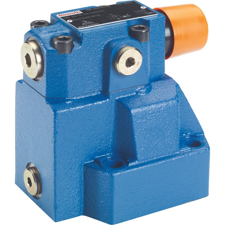
DR 20-5-5X/200Y
Rexroth
R900597892
用于底板安装。
油口布置符合ISO 5781。
用于螺纹连接。
插装阀结构。
四种可选调节方式:
• 旋钮。
• 带六角及保护帽的调节套。
• 带刻度的可锁定旋钮。
• 带刻度旋钮。
五种压力等级。
可选单向阀,仅适用于底板安装型。
防腐蚀结构。
DR 型压力阀为由二次回路控制的先导式减压阀。
减压阀主要由带主阀芯插装件(3)的主阀(1),以及带调节装置的先导阀(2)组成。
静止位置时,阀处于开启状态,液压油由 B 通道经主阀插装件(3)无阻碍地流向 A 通道。A 通道压力作用于主阀芯下侧,同时经喷嘴(4)作用于主阀芯(3)的弹簧加载侧,并经通道(5)作用于先导控制阀(2)中的钢球(6)。该压力还经喷嘴(7)、控制油路(8)、单向阀(9)和喷嘴(10)作用于钢球(6)。根据弹簧(11)的设定,钢球(6)前方、通道(5)及弹簧腔(12)内建立压力,使控制阀芯(13)保持开启。B 通道的液压油可经主阀插装件(3)无阻碍地流向 A 通道,直至 A 通道压力超过弹簧(11)的设定值并使钢球(6)开启,此时控制阀芯(13)向关闭方向移动。
A通道压力与弹簧(11)的设定压力达到平衡时,即达到所需减压值。
弹簧腔(14)的先导油始终经控制管路(15)外部回油至油箱。
可选装单向阀(16),以实现从通道 A 至通道 B 的自由回流。
压力表接口(17)可用于检查通道 A 中降低后的压力。
01 | 02 | 03 | 04 | 05 | 06 | 07 | 08 | 09 | 10 | 11 | 12 | ||
DR | – | 5X | / | Y | * |
01 | Pressure reducing valve, pilot-operated | DR | ||
02 | Valve complete (subplate mounting or threaded connection) | no code | ||
Pilot control valve without main spool insert (cartridge valve; do not enter nominal size) | C | |||
Pilot control valve with main spool insert (cartridge valve) | C30 | |||
03 | Size | Subplate mounting "–" | Threaded connection "G" | |
10 | ✔ | ✔ (G1/2) | 10 | |
16 | – | ✔ (G3/4) | 15 1) | |
25 | ✔ | ✔ (G1) | 20 | |
25 | – | ✔ (G1 1/4) | 25 1) | |
32 | ✔ | ✔ (G1 1/2) | 30 | |
04 | As cartridge valve (version "C", without main spool insert) | no code | ||
As cartridge valve (version "C30", with main spool insert) | – | |||
For subplate mounting | – | |||
For threaded connection | G | |||
Adjustment type | ||||
05 | Rotary knob | 4 | ||
Sleeve with hexagon and protective cap ("J3" version without protective cap; always with maximum pressure adjustment) | 5 | |||
Lockable rotary knob with scale | 6 2) | |||
Rotary knob with scale | 7 | |||
06 | Component series 50 … 59 (50 … 59: unchanged installation and connection dimensions) | 5X | ||
07 | Set pressure up to 50 bar | 50 | ||
Set pressure up to 100 bar | 100 | |||
Set pressure up to 200 bar | 200 | |||
Set pressure up to 315 bar | 315 | |||
Set pressure up to 350 bar (only version "M") | 350 | |||
Pilot oil supply | ||||
08 | Internal pilot oil supply, external pilot oil return | Y | ||
09 | With check valve (only for subplate mounting) | no code 1) | ||
Without check valve | M | |||
Corrosion resistance | ||||
10 | None | no code | ||
Improved corrosion protection (240 h salt spray test according to EN ISO 9227) (only version "5") | J3 | |||
Seal material (observe compatibility of seals with hydraulic fluid used, see "Technical data") | ||||
11 | NBR seals | no code | ||
FKM seals | V | |||
12 | Further details in the plain text | * | ||
| 1) | Not for version "J3" |
| 2) | H-Key with material no. R900008158 is included in the scope of delivery. |
Size | 10 | 16 | 25 | 25 | 32 | |||
Version | "10" | "15" | "20" | "25" | "30" | |||
Weight | Subplate mounting | "DR . .‒" | kg | 3.4 | - | 5.3 | - | 8 |
Cartridge valve | "DRC" | kg | 1.2 | |||||
"DRC30" | kg | 1.5 | ||||||
Threaded connection | "DR . G" | kg | 5.3 | 5.2 | 5.1 | 5 | 4.8 | |
Installation position | any | |||||||
Ambient temperature range | NBR seals | °C | -30 … +50 | |||||
FKM seals | °C | -20 … +50 | ||||||
Size | 10 | 16 | 25 | 32 | |||
Maximum operating pressure 1) | Port B | bar | 350 | ||||
Maximum inlet pressure 1) | Port B | bar | 350 | ||||
Maximum outlet pressure 1) | bar | 350 | |||||
Operating pressure range 1) | Anschluss A | bar | 10 … 350 | ||||
Maximum counter pressure 1) | Port Y | bar | 350 | ||||
Minimum set pressure | flow-dependent, see "characteristic curves" | ||||||
Maximum set pressure 1) | bar | 50 100 200 315 350 | |||||
Maximum flow | Subplate mounting | l/min | 150 | - | 300 | - | 400 |
Threaded connection | l/min | 150 | 300 | 400 | |||
Hydraulic fluid | see table "Hydraulic fluid" | ||||||
Hydraulic fluid temperature range | NBR seals | °C | -30 … +80 | ||||
FKM seals | °C | -20 … +80 | |||||
Viscosity range | mm²/s | 10 … 800 | |||||
Maximum admissible degree of contamination of the hydraulic fluid, cleanliness class according to ISO 4406 (c) 2) | Class 20/18/15 | ||||||
| 1) | 350 bar only possible at version "M" |
| 2) | The cleanliness classes specified for the components must be adhered to in hydraulic systems. Effective filtration prevents faults and simultaneously increases the life cycle of the components. For the selection of the filters, see www.boschrexroth.com/filter. |
Hydraulic fluid | Classification | Suitable sealing materials | Standards | Data sheet | |
Mineral oils | HL, HLP, HLPD, HVLP, HVLPD | NBR, FKM | DIN 51524 | 90220 | |
Bio-degradable | Insoluble in water | HETG | NBR, FKM | ISO 15380 | 90221 |
HEES | FKM | ||||
Soluble in water | HEPG | FKM | ISO 15380 | ||
Flame-resistant | Water-free | HFDU (glycol base) | FKM | ISO 12922 | 90222 |
HFDU (ester base) | FKM | ||||
HFDR | FKM | ||||
Containing water | HFC (Fuchs: Hydrotherm 46M, Renosafe 500; | NBR | ISO 12922 | 90223 | |
Important information on hydraulic fluids:
| |||||
Dimensions in mm
1 | Name plate |
2.1 | Y port for pilot oil return, external |
2.2 | Port Y optionally for external pilot oil return |
3 | Adjustment type "4" |
4 | Adjustment type "5" |
5 | Adjustment type "6" |
6 | Adjustment type "7" |
7 | Hexagon SW10 |
8 | Space required to remove the key |
9 | Valve mounting bores |
10 | Seal rings |
11 | Main spool insert |
12 | Seal ring |
13 | Seal ring |
14 | Seal ring |
15 | Support ring |
16 | Support ring |
Quantity | Hexagon socket head cap screws | Material number |
4 | ISO 4762 - M8 x 40 - 10.9-flZn/nc/480h/C (Friction coefficient μtotal = 0.09 … 0.14) Tightening torque MA = 31 Nm ±10 % | R913015798 |
Notice:
The dimensions are nominal dimensions which are subject to tolerances.
Dimensions in mm
1 | Name plate |
2.1 | Y port for pilot oil return, external |
3 | Adjustment type "4" |
4 | Adjustment type "5" |
5 | Adjustment type "6" |
6 | Adjustment type "7" |
7 | Hexagon SW10 |
8 | Space required to remove the key |
9 | Valve mounting bores |
17 | Pressure gauge connection |
Version | D1 | ØD2 | T1 |
mm | mm | ||
| "10" | G1/2 | 34 | 14 |
| "15" | G3/4 | 42 | 16 |
| "20" | G1 | 47 | 18 |
| "25" | G1 1/4 | 58 | 20 |
| "30" | G1 1/2 | 65 | 22 |
Notice:
The dimensions are nominal dimensions which are subject to tolerances.
Dimensions in mm
| Required surface quality of the valve contact surface |
1 | Name plate |
2.1 | Y port for pilot oil return, external |
2.2 | Port Y optionally for external pilot oil return |
3 | Adjustment type "4" |
4 | Adjustment type "5" |
5 | Adjustment type "6" |
6 | Adjustment type "7" |
7 | Hexagon SW10 |
8 | Space required to remove the key |
9 | Valve mounting bores |
17 | Pressure gauge connection |
18 | Identical seal rings for ports A and B Identical seal rings for ports X and Y |
19 | Port X without function (blind bore) |
20 | Locking pin |
Version | L1 | L2 | L3 | L4 | L5 | L6 | L7 | L8 | L9 | L10 | B1 | B2 | B3 | B4 | B5 | H1 | H2 | H3 |
mm | mm | mm | mm | mm | mm | mm | mm | mm | mm | mm | mm | mm | mm | mm | mm | mm | mm | |
| "10" | 96 | 35.5 | 33 | 42.9 | 21.5 | - | 7.2 | 21.5 | 31.8 | 35.8 | 85 | 50 | 66.7 | 58.8 | 7.9 | 112 | 92 | 28 |
| "20" | 116 | 37.5 | 35.4 | 60.3 | 39.7 | - | 11.1 | 20.6 | 44.5 | 49.2 | 102 | 59.5 | 79.4 | 73 | 6.4 | 122 | 102 | 37 |
| "30" | 145 | 33 | 29.8 | 84.2 | 59.5 | 42.1 | 16.7 | 24.6 | 62.7 | 67.5 | 120 | 76 | 96.8 | 92.8 | 3.8 | 130 | 110 | 46 |
Version | Quantity | Hexagon socket head cap screws | Material number |
"10" | 4 | ISO 4762 - M10 x 50 - 10.9-flZn/nc/480h/C (Friction coefficient μtotal = 0.09 … 0.14) Tightening torque MA = 60 Nm | R913015580 |
"20" | 4 | ISO 4762 - M10 x 60 - 10.9-flZn/nc/480h/C (Friction coefficient μtotal = 0.09 … 0.14) Tightening torque MA = 60 Nm | R913014770 |
"30" | 6 | ISO 4762 - M10 x 70 - 10.9-flZn/nc/480h/C (Friction coefficient μtotal = 0.09 … 0.14) Tightening torque MA = 60 Nm | R913014772 |
Subplates (separate order) with porting pattern according to ISO 5783, see data sheet 45100.
Notice:
The dimensions are nominal dimensions which are subject to tolerances.
Dimensions in mm
1 | Notice: Bore Ø32 can cut into Ø45 at any position. However, it must be observed that the connection bores and valve mounting bore are not damaged. |
2 | Support ring and seal rings are to be inserted into this bore before assembly of the main spool! |
3 | Nozzle, separate order |