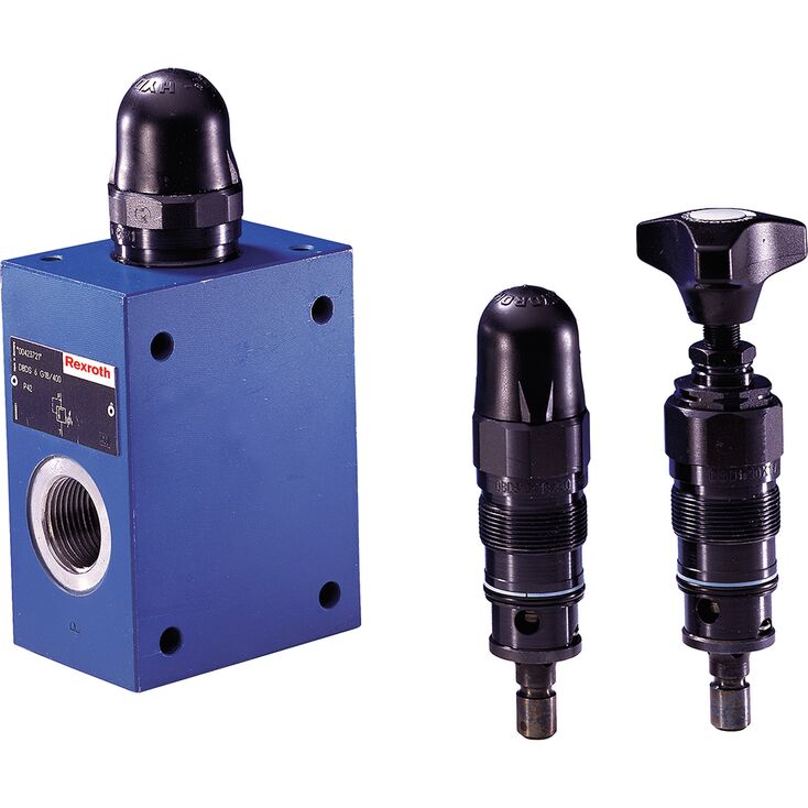
DBDS 6 K1X/315
Rexroth
R900423725
螺纹插装阀结构。
用于螺纹连接。
用于底板安装。
可选压力调节方式:带六角及保护帽的调节套、旋钮、手轮或可锁定旋钮。
防腐蚀结构。
DBD 型溢流阀为直动式座阀,用于限制系统压力。
该阀主要由阀套(1)、弹簧(2)、带阻尼活塞的阀锥(3,压力等级25…400 bar)或球(4,压力等级630 bar),以及调节装置(5)组成。系统压力可通过调节装置(5)无级设定。弹簧(2)将阀锥(3)或球(4)压向阀座。P通道连接系统,系统压力作用于阀锥表面或球。P通道压力超过弹簧(2)设定值时,阀锥或球克服弹簧开启,液压油由P流向T;压制成形的限位结构(6)限制阀锥行程。
为在整个压力范围内获得良好的调压性能,将全部压力范围划分为 7 个压力等级。每个压力等级对应一种弹簧,并可通过该弹簧设置相应的最大工作压力。
压力等级25…400 bar的版本,采用锥座阀。
压力等级630 bar的版本,采用球座阀,仅适用于NG10。
注意事项:
调节装置(5)采用防丢失结构。由于采用万向支承,完全卸载时,调节元件在调节装置(5)内仍保持松动、可移动状态。
压力等级“25”:若调节机构已完全卸载,仍未达到最低压力,则由于弹簧力和/或复位力较小,需要将调节元件“回拉”至止点。
需要调节或提高压力时,可再次旋入调节元件。
01 | 02 | 03 | 04 | 05 | 06 | 07 | 08 | 09 | 10 | 11 | 12 | 13 | 14 | 15 | 16 | 17 | 18 | 19 | 20 | 21 | 22 | |
DB | 5X | / | * |
01 | Pressure relief valve | DB |
02 | Without directional valve | no code |
03 | Pilot-operated valve (complete) | no code |
Pilot control valve without main spool insert (do not enter any size) | C | |
Pilot control valve with main spool insert (enter size 10 or 30) | C | |
Pilot control valve without main spool insert for subplate mounting (do not enter any size) | T 1) | |
04 | Size 10 | |
Subplate mounting "no code" | 10 | |
Threaded connection "G" | 10 (G1/2) | |
Size 16 | ||
Threaded connection "G" | 15 (G3/4) | |
Size 25 | ||
Subplate mounting "no code" | 20 | |
Threaded connection "G" | 20 (G1) | |
Threaded connection "G" | 25 (G1 1/4) | |
Size 32 | ||
Subplate mounting "no code" | 30 | |
Threaded connection "G" | 30 (G1 1/2) | |
05 | Without directional valve | no code |
Type of connection | ||
06 | Subplate mounting or cartridge valve | no code |
For threaded connection | G | |
Adjustment type for pressure adjustment | ||
07 | Rotary knob (not for version "C" and "T") | 1 |
Sleeve with hexagon and protective cap | 2 | |
Lockable rotary knob with scale | 3 2) | |
Rotary knob with scale | 7 | |
08 | Main spool Ø24 mm (all sizes) | – |
Main spool Ø28 mm (only for NG32) | N | |
09 | Component series 50 … 59 (50 … 59: unchanged installation and connection dimensions) | 5X |
10 | Set pressure up to 50 bar | 50 |
Set pressure up to 100 bar | 100 | |
Set pressure up to 200 bar | 200 | |
Set pressure up to 315 bar | 315 | |
Set pressure up to 350 bar | 350 | |
Pilot oil flow | ||
11 | External pilot oil supply, internal pilot oil return | X 3) |
Internal pilot oil supply, external pilot oil return | Y | |
Pilot oil supply and pilot oil return external | XY 3) | |
12 | Standard version | no code |
Valve for minimum cracking pressure (not for versions "without main spool insert" and not suitable for mutual relief) | U 4) | |
13 | Without switching shock damping | no code |
14 | Without directional valve | no code |
15 | Without directional valve | no code |
16 | Without manual override | no code |
Electrical connection | ||
17 | Without directional valve | no code |
18 | Without directional valve | no code |
Corrosion resistance | ||
19 | None | no code |
Improved corrosion protection (240 h salt spray test according to EN ISO 9227) | J3 5) | |
Seal material | ||
20 | NBR seals | no code |
FKM seals | V | |
Observe compatibility of seals with hydraulic fluid used. (Other seals upon request) | ||
Equipment Directive | ||
21 | Without type-examination procedure | no code |
Type-examination tested safety valve according to Pressure Equipment Directive 2014/68/EU | E | |
22 | Further details in the plain text | * |
| 1) | DBT corresponds to DBC, however with closed central bore |
| 2) | H-Key with material no. R900008158 is included in the scope of delivery. |
| 3) | Not with version "DBC" |
| 4) | Only possible up to pressure rating 315 bar |
| 5) | Only version "2", however without protective cap |
(Component series 5X according to Pressure Equipment Directive 2014/68/EU)
NG | Type designation | Component marking | Maximum flow qVmaxin l/min with pilot oil return | Set response overpressure p in bar | |
external "Y" | internal "–" | ||||
10 | | TÜV.SV.▢ – 851.12.F.G.p | 170 230 230 230 | 130 200 200 200 | 30 ... 60 61 ... 110 111 ... 210 211 ... 350 |
25 | | TÜV.SV.▢ – 852.22.F.G.p | 250 270 420 450 | 180 210 320 400 | 30 ... 60 61 ... 110 111 ... 210 211 ... 350 |
32 | | TÜV.SV.▢ – 853.32.F.G.p | 600 600 650 700 | 225 340 540 580 | 30 ... 60 61 ... 110 111 ... 210 211 ... 350 |
1 | For subplate mounting | no code |
For threaded connection | G | |
Adjustment type for pressure adjustment | ||
2 | Hand wheel (pressure adjustment sealed, unloading or setting of a lower response pressure possible!) | 1 |
With sealed protective cap (no adjustment/unloading possible) | 2 | |
Pressure | ||
3 | To be entered by the customer, e.g. pressure adjustment ≥ 30 bar and possible in 5 bar steps. | e.g. 150 |
Pilot oil flow | ||
4 | Pilot oil supply internal, pilot oil return internal | no code |
Pilot oil supply internal, pilot oil return external (Recommendation) | Y 1) | |
5 | NBR seals | no code |
FKM seals | V | |
▢ | Value entered at the factory | |
| 1) | Pilot oil supply external "X" not possible |
Size | 6 | 8 | 10 | 15 | 20 | 25 | 30 | ||
Weight | See dimensions | ||||||||
Installation position | any | ||||||||
Ambient temperature range | NBR seals | °C | -30 … +80 | ||||||
FKM seals | °C | -15 … +80 | |||||||
Minimum stability of the housing materials | Housing materials are to be selected so that there is sufficient safety for all imaginable operating conditions (e.g. with regard to pressure resistance, thread stripping strengths and tightening torques). | ||||||||
Size | 6 | 8 | 10 | 15 | 20 | 25 | 30 | ||
Maximum operating pressure | Inlet | bar | 400 | 630 | 400 | 315 | |||
Outlet | bar | 315 | |||||||
Maximum flow (standard valves) | See characteristic curves | ||||||||
Hydraulic fluid | see table | ||||||||
Hydraulic fluid temperature range | NBR seals | °C | -30 … +80 | ||||||
FKM seals | °C | -15 … +80 | |||||||
Viscosity range | mm²/s | 10 … 800 | |||||||
Maximum admissible degree of contamination of the hydraulic fluid 1) | Class 20/18/15 according to ISO 4406 (c) | ||||||||
| 1) | The cleanliness classes specified for the components must be adhered to in hydraulic systems. Effective filtration prevents faults and simultaneously increases the life cycle of the components. For the selection of the filters, see www.boschrexroth.com/filter. |
Hydraulic fluid | Classification | Suitable sealing materials | Standards | Data sheet | |
Mineral oils | HL, HLP, HLPD, HVLP, HVLPD | NBR, FKM | DIN 51524 | 90220 | |
Bio-degradable | Insoluble in water | HETG | NBR, FKM | ISO 15380 | 90221 |
HEEG | FKM | ||||
Soluble in water | HEPG | FKM | ISO 15380 | ||
Important information on hydraulic fluids:
| |||||
注意:
T 口的液压背压以 1:1 的比例叠加到通过调节装置设定的阀响应压力上。
示例:
通过弹簧预紧调节阀的压力(见“产品描述”第 2 项)p spring = 200 bar
T 口的液压背压:p hydraulic = 50 bar
⇒ 响应压力 = p spring + p hydraulic = 250 bar
(元件系列 1X,依据压力设备指令 2014/68/EU)
Ambient temperature range | °C | -10 … +80 |
Set response pressure | see last figure of the component marking | |
Maximum counter pressure in the discharge line | See characteristic curves "Counter pressure in the discharge line” | |
Maximum flow | The last but one figure of the component marking attached at the safety valve is always binding. For valve types which have a variable maximum flow depending on the response pressure, the discharge coefficient is specified at this place. | |
Hydraulic fluid | Hydraulic fluids according to DIN 51524: Hydraulic oils HL and HLP are suitable for safety valves with NBR or FKM seals. | |
Hydraulic fluid temperature range | -10 … +60 °C | |
Viscosity range | 12 … 230 mm²/s |
(dimensions in mm)
Dimensions in mm
1.1 | Adjustment type "S” (example) Grub screw with hexagon and protective cap; Internal hexagon (NG6 … NG20) External hexagon (NG25 and 30) |
2 | Name plate |
3 | 4 valve mounting bores |
4 | Additional port (P), optional (e.g. for pressure measurement); not possible for NG10 and pressure rating > 400 bar (= version “SO292”). Dimensions see dimensions D4, tightening torque see table. |
NG | B1 | B2 | ØD1 | D2 | ØD3 | D4 | H1 | H2 | L1 | L2 | L3 | L4 | L5 | L6 | T1 | T2 |
mm | mm | mm | mm | mm | mm | mm | mm | mm | mm | mm | mm | mm | mm | |||
| 6 | 45 | 60 | 25 | M6 | 6.6 | G1/4 | 25 | 40 | 80 | 4 | 15 | 55 | 40 | 20 | 10 | 12 |
| 8 | 60 | 80 | 28 | M8 | 9 | G3/8 | 40 | 60 | 100 | 4 | 20 | 70 | 48 | 21 | 15 | 12 |
| 10 | 60 | 80 | 34 | M8 | 9 | G1/2 | 40 | 60 | 100 | 4 | 20 | 70 | 48 | 21 | 15 | 14 |
| 15 | 70 | 100 | 42 | M8 | 9 | G3/4 | 50 | 70 | 135 | 4 | 20 | 100 | 65 | 34 | 18 | 16 |
| 20 | 70 | 100 | 47 | M8 | 9 | G1 | 50 | 70 | 135 | 5.5 | 20 | 100 | 65 | 34 | 18 | 18 |
| 25 | 100 | 130 | 56 | M10 | 11 | G1 1/4 | 60 | 90 | 180 | 5.5 | 25 | 130 | 85 | 35 | 20 | 20 |
| 30 | 100 | 130 | 65 | M10 | 11 | G1 1/2 | 60 | 90 | 180 | 5.5 | 25 | 130 | 85 | 35 | 20 | 22 |
NG | Tightening torques MA in Nmfor fittings 1) | Weight, approx. in kg | |
Plug screw (4) | Pipe fittings | ||
6 | 30 Nm | 60 Nm | 1,5 Kg |
8 | 40 Nm | 90 Nm | 3,7 Kg |
10 | 60 Nm | 130 Nm | 3,7 Kg |
15 | 80 Nm | 200 Nm | 6,4 Kg |
20 | 135 Nm | 380 Nm | 6,4 Kg |
25 | 480 Nm | 500 Nm | 13,9 Kg |
30 | 560 Nm | 600 Nm | 13,9 Kg |
| 1) | The tightening torques are guidelines, referring to the maximum operating pressure and when using a manual torque wrench (tolerance ±10 %). |
(dimensions in mm)
Dimensions in mm
Dimensions in mm
1.1 | Adjustment type "S” – Grub screw with hexagon and protective cap; internal hexagon (NG6 … NG20), external hexagon (NG30) |
1.2 | Adjustment type “H” – rotary knob (NG6 … NG20), hand wheel (NG30) |
1.3 | Adjustment type "A” – lockable rotary knob NG6 … NG10 (NG20 …100 bar) |
4 | Port P, at any place at the circumference or at the front side |
5 | Port T, at any place at the circumference |
6 | Type designation |
7 | Pressure rating (stamped in) |
8 | Marking (adjustment of the zero position after the valve has been screwed in; then fixing of the ring by horizontal shifting until it engages on the plug screw SW6). |
9 | Depth of fit |
10 | Lock nut, tightening torque MA = 10+5 Nm |
11 | Space required to remove the key |
12 | Minimum stability of the housing materials, see "Technical data". |
1) | Maximum dimension |
2) | All seal ring in sertion faces are rounded and free of burrs; tolerance for all angles ± 0.5° |
NG | ØD11 | ØD12 | ØD13 | L17 | L18 | L19 | L20 | L21 | L22 | L23 | L24 | SW1 | SW2 | SW3 | SW4 | SW5 | SW6 | Weight (approx.) |
mm | mm | mm | mm | mm | mm | mm | mm | mm | mm | mm | mm | mm | mm | mm | mm | mm | kg | |
| 6 | 34 | 60 | - | 72 | 11 | 83 | 28 | 20 | - | - | 64.5 | 32 | 30 | 19 | 6 | - | 30 - | 0.4 |
| 8 | - | - | - | - | - | - | - | - | - | - | - | - | - | - | - | - | - - | |
| 10 | 38 | 60 | - | 68 | 11 | 79 | 28 | 20 | - | - | 77 | 36 | 30 | 19 | 6 | - | 30 - | 0.5 |
| 15 | - | - | - | - | - | - | - | - | - | - | - | - | - | - | - | - | - - | |
| 20 | 48 | 60 | - | 65 | 11 | 77 | 28 | 20 | - | - | 106 | 46 | 36 | 19 | 6 | - | 30 - | 1 |
| 25 | - | - | - | - | - | - | - | - | - | - | - | - | - | - | - | - | - - | |
| 30 | 63 | - | 80 | 83 | - | - | - | - | 11 | 56 | 131 | 60 | 46 | 19 | - | 13 | - - | 2.2 |
NG | Pressure rating in bar | ||
Up to 200 | Up to 400 | Up to 630 | |
6 | 50±5 | 80±5 | ‒ |
10 | 100±5 | 150±10 | 200±10 |
20 | 150±10 | 300±15 | ‒ |
30 | 350±20 | 500±30 | ‒ |
The tightening torques are guidelines with a friction coefficient μtotal = 0.12 and when using a manual torque wrench. | |||
NG | D14 | ØD15 | ØD16 | ØD17 | ØD18 | ØD19 | L25 | L26 | L27 | L28 | L29 | L30 | L31 | α1 | |||
mm | mm | mm | mm | mm | mm | mm | mm | mm | mm | mm | mm | mm | mm | ° | |||
| 6 | M28 x 1.5 | 25 | H9 - | 6 | 15 | 24.9 | + 0.15 - 0.2 | 12 | 15 | 19 | 30 | 36 | 45 | 56.5 | ± 5.5 | 65 | 15 |
| 8 | - | - | - - | - | - | - | - - | - | - | - | - | - | - | - | - | - | - |
| 10 | M35 x 1.5 | 32 | H9 - | 10 | 18.5 | 31.9 | + 0.16 - 0.2 | 15 | 18 | 23 | 35 | 41.5 | 52 | 67.5 | ± 7.5 | 80 | 15 |
| 15 | - | - | - - | - | - | - | - - | - | - | - | - | - | - | - | - | - | - |
| 20 | M45 x 1.5 | 40 | H9 - | 20 | 24 | 39.9 | + 0.16 - 0.2 | 22 | 21 | 27 | 45 | 55 | 70 | 91.5 | ± 8.5 | 110 | 20 |
| 25 | - | - | - - | - | - | - | - - | - | - | - | - | - | - | - | - | - | - |
| 30 | M60 x 2 | 55 | H9 - | 30 | 38.75 | 54.9 | + 0.17 - 0.2 | 34 | 23 | 29 | 45 | 63 | 84 | 113.5 | ± 11.5 | 140 | 20 |
((dimensions in mm)
Dimensions in mm
Dimensions in mm
1.1 | Adjustment type "S” – Grub screw with hexagon and protective cap; internal hexagon (NG6 … NG20), external hexagon (NG30) |
2 | Name plate |
4 | Additional port (P), optional (e.g. for pressure measurement); not possible for NG10 and pressure rating > 400 bar (= version “SO292”). Tightening torques see dimensional table) |
15 | Locking pin (only with type-examination tested safety valves) |
For reasons of stability, use exclusively the following valve mounting screws (separate order):
4 hexagon socket head cap screws ISO 4762...-flZn-240h-L
(friction coefficient μtotal = 0.09 to 0.14)
NG | Dimensions | Property class | MA in Nm 1) | Material number |
6 | M6 x 50 | 10.9 | 12,5 Nm | R913000151 |
10 | M8 x 70 | 10.9 | 28 Nm | R913000149 |
20 | M8 x 90 | 12.9 | 28 Nm | R913000150 |
30 | M10 x 110 | 12.9 | 56 Nm | R913000148 |
| 1) | For tightening, use a manual torque wrench with a tolerance ≤10 %. |
NG | B1 | B2 | ØD3 | H2 | L1 | L2 | L3 | L4 | L5 | L6 | L18 | Port P | Weight (approx.) |
mm | mm | mm | mm | mm | mm | mm | mm | mm | mm | mm | kg | ||
| 6 | 45 | 60 | 6.6 | 40 | 80 | 4 | 15 | 55 | 40 | 20 | 15 | G1/4 | 1.5 |
| 10 | 60 | 80 | 9 | 60 | 100 | 4 | 20 | 70 | 45 | 21 | 15 | G1/2 | 3.7 |
| 20 | 70 | 100 | 9 | 70 | 135 | 5.5 | 20 | 100 | 65 | 34 | 15 | G3/4 | 6.4 |
| 30 | 100 | 130 | 11 | 90 | 180 | 5.5 | 25 | 130 | 85 | 35 | 15 | G1 1/4 | 13.9 |
(Component series 1X, according to Pressure Equipment Directive 2014/68/EU) (dimensions in mm)
Dimensions in mm
1.2 | Adjustment type “H” – rotary knob (NG6 … NG20), hand wheel (NG30) |
1.4 | Adjustment type "S" – hexagon with safety cap |
4 | Port P, at any place at the circumference or at the front side |
6 | Type designation |
7 | Pressure rating (stamped in) |
10 | Lock nut, tightening torque MA = 10+5 Nm |
1) | Maximum dimension with lowest set response pressure |
2) | The tightening torques are guidelines with a friction coefficient μtotal = 0.12 and when using a manual torque wrench. |
NG | ØD11 | ØD12 | ØD13 | L17 | L18 | L19 | L22 | L23 | L24 | SW1 | SW2 | SW3 | Weight (approx.) |
mm | mm | mm | mm | mm | mm | mm | mm | mm | mm | mm | mm | kg | |
| 6 | 34 | 60 | - | 80 | 11 | 83 | - | - | 64.5 | 32 | 30 | 19 | 0.4 |
| 8 | - | - | - | - | - | - | - | - | - | - | - | - | |
| 10 | 38 | 60 | - | 76 | 11 | 79 | - | - | 77 | 36 | 30 | 19 | 0.5 |
| 15 | - | - | - | - | - | - | - | - | - | - | - | - | |
| 20 | 48 | 60 | - | 73 | 11 | 77 | - | - | 106 | 46 | 36 | 19 | 1 |
| 25 | - | - | - | - | - | - | - | - | - | - | - | - | |
| 30 | 63 | - | 80 | 91 | - | - | 11 | 56 | 131 | 60 | 46 | 19 | 2.2 |
NG | Pressure rating in bar | ||
Up to 200 | Up to 400 | Up to 630 | |
6 | 50±5 | 80±5 | ‒ |
10 | 100±5 | 150±10 | 200±10 |
20 | 150±10 | 300±15 | ‒ |
30 | 350±20 | 500±30 | ‒ |
The tightening torques are guidelines with a friction coefficient μtotal = 0.12 and when using a manual torque wrench. | |||
(Component series 1X, according to Pressure Equipment Directive 2014/68/EU) (dimensions in mm)
Notice:
With valves type DBDH.K..1X/..E, the hand wheel must be removed and reassembled before the front panel assembly of the screw-in cartridge valve.
Dimensions in mm
NG | B1 | B2 | H1 | H2 | ØD1 | ØD2 | R1 | ||
mm | mm | mm | mm | mm | mm | mm | |||
| 6 | 45 | 12.5 | 25 | 22.5 | 7 | H13 | 40 | H13 | 8 |
| 8 | |||||||||
| 10 | 60 | 20.5 | 40 | 20.5 | 9 | H13 | 44 | H13 | 8 |
| 15 | |||||||||
| 20 | 70 | 24 | 50 | 24 | 9 | H13 | 55 | H13 | 8 |
| 25 | |||||||||
| 30 | 100 | 29.5 | 60 | 29.5 | 11 | H13 | 73 | H13 | 8 |
| 2) The tightening torques are guidelines with a friction coefficientμtotal = 0.12 and when using a manual torque wrench. | |
| 1) Component series 1X, according to Pressure Equipment Directive97/23/EC | |
| 1) As replacement, you can also use specified screws according to DIN 912. | |
| 2) For tightening, use a manual torque wrench with a tolerance ≤10 %. |