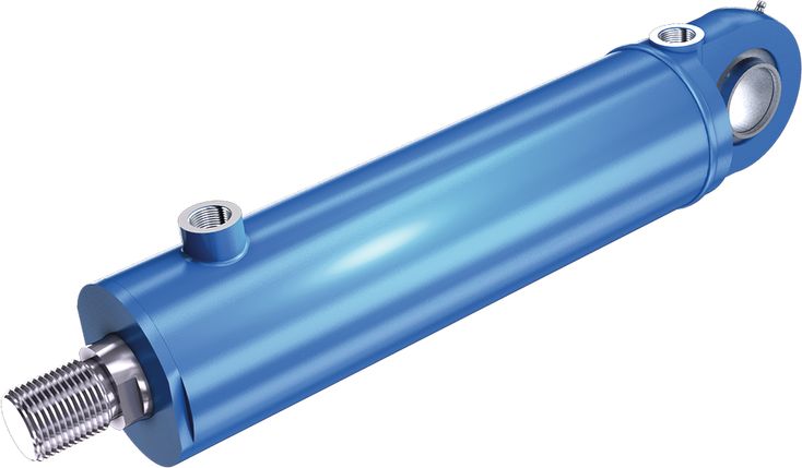
四种安装方式。
总成长度短。
01 | 02 | 03 | 04 | 05 | 06 | 07 | 08 | 09 | 10 | 11 | 12 | 13 | 14 | 15 | 16 | 17 | 18 | ||||
CD | L2 | / | / | / | 1X | / | B | 1 | 1 | C | U | W | * |
Type | ||
01 | Single rod cylinder | CD |
02 | Series L2 | L2 |
Types of mounting | ||
03 | Self-aligning clevis at cylinder base | MP5 |
Round flange at the cylinder head | MF31) | |
Trunnion | MT41;2) | |
Without mounting | M003) | |
04 | Piston Ø (ØAL) from 25 ... 200 mm; possible version see Technical data | ... |
05 | Piston rod Ø (ØMM) with nominal pressure 160 bar: 14, 18, 22, 28, 36, 45, 56 and 70 mm possible; see Technical data | ... |
Piston rod Ø (ØMM) with nominal pressure 250 bar: 25, 32, 40, 50, 63, 80, 100 and 125 mm possible; see Technical data | ||
06 | Stroke length in mm; observe admissible stroke lengths; see Project planning information | ... |
Design principle | ||
07 | Head and base screwed in | C3) |
Head screwed in, base welded | D4) | |
08 | Component series 10 ... 19 (10 ... 19: unchanged installation and connection dimensions) | 1X |
Line connection / version | ||
09 | Pipe thread according to ISO 228/1 | B |
Line connection/position at cylinder head | ||
10 | View to piston rod | 1 |
Line connection/position at cylinder base | ||
11 | View to piston rod | 1 |
Piston rod design | ||
12 | Hard chromium-plated | C |
Piston rod end | ||
13 | Thread | H4) |
Piston rod end \u201cH\u201d with mounted swivel head CGKD | K4) | |
With swivel head, cannot be disassembled | F4;5) | |
Internal thread | E3) | |
Piston rod end \u201cE\u201d with mounted swivel head CGKL | L3) | |
End position cushioning | ||
14 | Without end position cushioning | U |
Seal design | ||
15 | Standard seal system (suitable for mineral oils HL, HLP) | M |
Standard seal system FKM (for phosphate ester HFDR) | V | |
Option 1 | ||
16 | Without option | W |
Option 2 | ||
17 | Without option | W |
With piston rod extension \u201cLY\u201d in mm | Y6) | |
18 | Further details in the plain text | * |
| 1) | Only piston Ø (ØAL) 25 ... 125 mm |
| 2) | Trunnion position freely selectable. When ordering, always specify the dimension "XV/XU" in the plain text in mm (see order example) |
| 3) | Only piston Ø (ØAL) 25 ... 32 mm |
| 4) | Only piston Ø (ØAL) 40 ... 200 mm |
| 5) | Only MP5; MT4 |
| 6) | When ordering, always specify the piston rod extension dimension "LY" in the plain text in mm (see order example) |
| Order example: | |
| CDL2MT4/100/56/200D1X/B11CHUMWY, LY = 20 mm, XV = 245 mm | |
| CDL2MF3/80/45/100D1X/B11CHUMWW |
Installation position | Any | |
Ambient temperature range | °C | -20 \u2026 +80 |
Primer coat | Gentian blue (RAL 5010) | |
Minimum layer thickness of the priming 1) | µm | 40 |
| 1) | Other colors upon request. With cylinders and attachment parts, the following surfaces are not primed or painted: ▶ All fit diameters to the customer\u2019s side ▶ Sealing surfaces for line connection The unpainted surfaces are protected using a corrosion protection agent (MULTICOR LF 80). |
Piston rod Ø | mm | 14 | 18 | 22 | 25 | 28 | 32 | 36 | 40 | 45 | 50 | 56 | 63 | 70 | 80 | 100 | 125 |
Nominal pressure 1) | bar | 160 | 250 | 160 | 250 | 160 | 250 | 160 | 250 | 160 | 250 | 160 | 250 | ||||
Operating pressure, min. (without load) 2) (without load) 2) | bar | 10 | |||||||||||||||
Static test pressure | bar | 375 | |||||||||||||||
Hydraulic fluid temperature range | °C | -20 \u2026 +80 | |||||||||||||||
Operating viscosity range | mm²/s | 12 \u2026 380 | |||||||||||||||
Optimum viscosity at operating temperature | mm²/s | 20 \u2026 100 | |||||||||||||||
Maximum admissible degree of contamination of the hydraulic fluid, cleanliness class according to ISO 4406 (c) 3) | Class 20/18/15 according to ISO 4406 (c) | ||||||||||||||||
Maximum stroke velocity (depending on line connection) | m/s | 0.5 | |||||||||||||||
| 1) | The cylinders of this series have been designed for 2 million load cycles at their nominal pressure. Higher operating pressures upon request. If there are extreme loads, such as high sequence cycles, the suitability of mounting elements and threaded piston rod connections for the application must be checked due to standardized geometries. |
| 2) | A minimum operating pressure is required in order to guarantee good functioning of the cylinder. Without load, a minimum pressure is recommend, for lower pressures, please contact us. |
| 3) | The cleanliness classes specified for the components must be adhered to in hydraulic systems. Effective filtration prevents faults and simultaneously increases the life cycle of the components. For the selection of the filters, see www.boschrexroth.com/filter. |
Hydraulic fluid | Classification | Suitable sealing materials | Standards | |
Mineral oil | HL, HLP | FKM, NBR | DIN 51524 | |
Flame-resistant | Water-free | HFDR | FKM | ISO 12922 |
Piston | Piston rod | with 0 mm stroke length | per 100 mm stroke length | |||
ØAL | ØMM | MP5 | MF3 | MT4 | M00 | |
mm | kg | kg | kg | kg | kg | |
| 25 | 14 mm / - | 1 | 1 | 1 | 1 | 0.4 |
| 32 | 18 mm / - | 2 | 2 | 2 | 2 | 0.6 |
| 40 | 22 mm / - | 2 | 3 | 3 | - | 0.9 |
| 25 mm / - | 2 | 4 | 4 | - | 1.1 | |
| 50 | 28 mm / - | 3 | 4 | 5 | - | 1.2 |
| 32 mm / - | 4 | 5 | 7 | - | 1.5 | |
| 63 | 36 mm / - | 5 | 7 | 9 | - | 1.8 |
| 40 mm / - | 6 | 9 | 12 | - | 2.3 | |
| 80 | 45 mm / - | 9 | 13 | 15 | - | 2.9 |
| 50 mm / - | 11 | 15 | 20 | - | 3.8 | |
| 100 | 56 mm / - | 15 | 20 | 26 | - | 4.6 |
| 63 mm / - | 19 | 26 | 36 | - | 6 | |
| 125 | 70 mm / - | 29 | 35 | 46 | - | 7.2 |
| 80 mm / - | 38 | 43 | 67 | - | 10.1 | |
| 160 | 100 mm / - | 67 | - | - | - | 15.1 |
| 200 | 125 mm / - | 110 | - | - | - | 22 |
Rexroth 油缸符合工业应用的可靠性建议。在额定压力的 70 %、活塞杆不承受负载、最大速度 0.5 m/s 的条件下,连续空载运行可达到 ≥ 10,000,000 次往复行程,或活塞累计行程 3,000 km,故障率低于 5 %。
边界条件与应用条件
必须确保运动轴线,以及液压缸和活塞杆安装点的机械对中。应避免活塞杆与活塞导向部位承受侧向力。必要时,应考虑液压缸(MP5 或 MT4)或活塞杆的自重。
必须注意活塞杆和/或液压缸的屈曲长度/屈曲载荷。
液压缸在任何运行状态下,都必须遵守最大允许工作压力。应考虑环形面积与活塞面积之比所造成的压力增压,以及可能存在的节流部位。
应避免腐蚀性微细颗粒、蒸气、高温等有害环境影响,以及液压油的污染和劣化。
标准:
Rexroth 标准;活塞 Ø (ØAL) 与活塞杆 Ø (ØMM) 等主要尺寸符合 ISO 3320。
验收:
每个油缸均按 Rexroth 标准测试,并符合 ISO10100:2001。
安全说明:
液压缸的装配、调试和维护必须遵守操作说明 07100-B!保养和维修必须由 Bosch Rexroth AG 或为此经过专门培训的人员执行。因非 Bosch Rexroth AG 执行的装配、维护或维修造成的损坏,不予保修。
液压缸检查清单:
若油缸的特性和/或应用参数偏离数据表所列数值,则只能按要求作为特殊型号提供。询价时,必须在液压缸检查清单(07200)中说明特性和/或应用参数的变化。
本清单不保证完整。如对介质相容性,或超出边界条件、应用条件的情况有疑问,请联系我们。
ICS(交互式目录系统)是液压缸选型与项目规划辅助工具。它通过逻辑引导的型号代码查询,帮助机械和系统设计人员快速、可靠地找到合适的液压缸方案,使设计与项目规划工作更快捷高效。完成引导式产品选择后,用户即可快速、可靠地获得所选元件的准确技术参数,以及适用于各种常见 CAD 系统、采用相应文件格式的 2D 和 3D CAD 数据。
这使用户能够在降低成本的同时提升竞争力。
Piston | Piston rod at nominal pressure 160 bar | Area ratio | Areas | Force at 160 bar | Flow at 0.1 m/s | Maximum available stroke length | |||
Piston | Ring | Pressure | Traction | Off | On | ||||
ØAL | ØMM | φ A1/A3 | A1 | A3 | F1 | F3 | qV1 | qV3 | |
mm | cm² | cm² | kN | kN | l/min | l/min | mm | ||
| 25 | 14 mm / - | 1.46 | 4.91 | 3.37 | 7.85 1) | 5.39 | 2.94 2) | 2.02 | 600 |
| 32 | 18 mm / - | 1.46 | 8.04 | 5.5 | 12.86 1) | 8.79 | 4.82 2) | 3.3 | 800 |
| 40 | 22 mm / - | 1.43 | 12.56 | 8.76 | 20.1 1) | 14.02 | 7.54 2) | 5.26 | 1000 |
| 50 | 28 mm / - | 1.46 | 19.63 | 13.47 | 31.4 1) | 21.55 | 11.78 2) | 8.08 | 1200 |
| 63 | 36 mm / - | 1.49 | 31.16 | 20.98 | 49.85 1) | 33.57 | 18.69 2) | 12.59 | 1400 |
| 80 | 45 mm / - | 1.46 | 50.24 | 34.34 | 80.38 1) | 54.95 | 30.14 2) | 20.61 | 1700 |
| 100 | 56 mm / - | 1.46 | 78.5 | 53.88 | 125.6 1) | 86.21 | 47.1 2) | 32.33 | 2000 |
| 125 | 70 mm / - | 1.46 | 122.66 | 84.19 | 196.25 1) | 134.71 | 73.59 2) | 50.51 | 2300 |
| 1) | Theoretical static cylinder force (without consideration of the efficiency and admissible load for attachment parts such as swivel heads, plates, or valves, etc.) |
| 2) | Stroke velocity |
Piston | Piston rod at nominal pressure 250 bar | Area ratio | Areas | Force at 250 bar | Flow at 0.1 m/s | Maximum available stroke length | |||
Piston | Ring | Pressure | Traction | Off | On | ||||
ØAL | ØMM | φ A1/A3 | A1 | A3 | F1 | F3 | qV1 | qV3 | |
mm | cm² | cm² | kN | kN | l/min | l/min | mm | ||
| 40 | 25 mm / - | 1.64 | 12.56 | 7.65 | 31.4 1) | 19.13 | 7.54 2) | 4.59 | 1000 |
| 50 | 32 mm / - | 1.69 | 19.63 | 11.59 | 49.06 1) | 28.97 | 11.78 2) | 6.95 | 1200 |
| 63 | 40 mm / - | 1.68 | 31.16 | 18.6 | 77.89 1) | 46.49 | 18.69 2) | 11.16 | 1400 |
| 80 | 50 mm / - | 1.64 | 50.24 | 30.62 | 125.6 1) | 76.54 | 30.14 2) | 18.37 | 1700 |
| 100 | 63 mm / - | 1.66 | 78.5 | 47.34 | 196.25 1) | 118.36 | 47.1 2) | 28.41 | 2000 |
| 125 | 80 mm / - | 1.69 | 122.66 | 72.42 | 306.64 1) | 181.04 | 73.59 2) | 43.45 | 2300 |
| 160 | 100 mm / - | 1.64 | 200.96 | 122.46 | 502.4 1) | 306.15 | 120.58 2) | 73.48 | 2600 |
| 200 | 125 mm / - | 1.64 | 314 | 191.34 | 785 1) | 478.36 | 188.4 2) | 114.81 | 3000 |
| 1) | Theoretical static cylinder force (without consideration of the efficiency and admissible load for attachment parts such as swivel heads, plates, or valves, etc.) |
| 2) | Stroke velocity |
Installation dimensions | WC | XO/XF1) | XV/XU | |
Mounting type | MF3 | MP5 | MT4 | |
Stroke length in mm | Tolerances in mm | Stroke tolerances in mm | ||
≤ 1.250 | ±3 | ±2 | ±2 | +2,5 |
< 1.250 \u2026 ≤ 3.000 | ±4 | ±3 | ±4 | ±4 |
| 1) | Including stroke length |
Piston Ø (ØAL) 25 \u2026 32 mm
| 1) | X = stroke length |
Piston Ø (ØAL) 40 \u2026 200 mm
| 1) | X = stroke length |
| 2) | Related bolt Ø j6 |
| 3) | Lubricating nipple, cone head form A according to DIN 71412 |
ØAL | ØMM at nominal pressure 160 bar | KK | A | NV | W | WA | ØD | Y | YA | PJ | XO | XF | EE | X1 | X3 | LT | LF | MS | ØCX | EX | EP max. | EF | ØCN | EN | EU max. | |||||||
mm | mm | mm | mm | mm | mm | mm | mm | mm | mm | mm | mm | mm | mm | mm | mm | mm | mm | mm | mm | mm | mm | mm | mm | mm | mm | mm | mm | |||||
| 25 | 14 mm / - | M10 | 26 | 12 | 10 | - | 32 | 44 | - | 26 | 131 | 158 | G1/8 | 24.5 | ± 1 | - | - | 27 | - | 145 | ± 2 | - | - - | - | - | - | - | 10 | 0 - 0.008 | 9 | h12 | 7.5 |
| 32 | 18 mm / - | M12 | 28 | 15 | 11 | - | 40 | 48 | - | 31 | 148 | 180 | G1/4 | 33 | ± 1 | - | - | 32 | - | 17 | ± 2 | - | - - | - | - | - | - | 12 | 0 - 0.008 | 10 | h12 | 8.5 |
| 40 | 22 mm / - | M16 x 1.5 | 22 | 17 | 13 | 44 | 50 | 60 | 91 | 50 | 140 | 171 | G1/4 | 39 | ± 1 | 29 | ± 1 | 24 | 23 | 28 | ± 2 | 20 | H7 | 20 | 16 | 28 | ± 2 | - | - - | - | - - | - |
| 50 | 28 mm / - | M20 x 1.5 | 28 | 22 | 13 | 50 | 60 | 62 | 99 | 57 | 157 | 194 | G3/8 | 45 | ± 1 | 33 | ± 1 | 31 | 29 | 33 | ± 2 | 25 | H7 | 25 | 20 | 33 | ± 2 | - | - - | - | - - | - |
| 63 | 36 mm / - | M27 x 2 | 36 | 28 | 14 | 63 | 75 | 68 | 117 | 69 | 182 | 231 | G1/2 | 55 | ± 1 | 40 | ± 1 | 38 | 34 | 42 | ± 2 | 32 | H7 | 32 | 22 | 42 | ± 2 | - | - - | - | - - | - |
| 80 | 45 mm / - | M33 x 2 | 45 | 36 | 16 | 76 | 95 | 84 | 144 | 76 | 208 | 268 | G1/2 | 65 | ± 1 | 53 | ± 1 | 46 | 44 | 51 | ± 2 | 40 | H7 | 40 | 26 | 51 | ± 2 | - | - - | - | - - | - |
| 100 | 56 mm / - | M42 x 2 | 56 | 46 | 18 | 88 | 120 | 90 | 160 | 85 | 227 | 297 | G3/4 | 80 | ± 1 | 63 | ± 1 | 54 | 50 | 61 | ± 2 | 50 | H7 | 50 | 34 | 61 | ± 2 | - | - - | - | - - | - |
| 125 | 70 mm / - | M48 x 2 | 63 | 60 | 20 | 106 | 150 | 99 | 185 | 93 | 259 | 345 | G3/4 | 95 | ± 1 | 78 | ± 1 | 65 | 63 | 76 | ± 2 | 63 | H7 | 63 | 42 | 76 | ± 2 | - | - - | - | - - | - |
ØAL | ØMM at nominal pressure 250 bar | KK | A | NV | W | WA | ØD | Y | YA | PJ | XO | XF | EE | X1 | X3 | LT | LF | MS | ØCX | EX | EP max. | EF | ||||||
mm | mm | mm | mm | mm | mm | mm | mm | mm | mm | mm | mm | mm | mm | mm | mm | mm | mm | mm | mm | mm | mm | mm | mm | |||||
| 40 | 25 mm / - | M20 x 1.5 | 28 | 19 | 15 | 41 | 52 | 62 | 88 | 54 | 147 | 173 | G1/4 | 46 | ± 1 | 30 | ± 1 | 29 | 29 | 31 | ± 2 | 25 | H7 | 25 | h12 | 20 | 33 | ± 2 |
| 50 | 32 mm / - | M27 x 2 | 36 | 27 | 15 | 52 | 62 | 64 | 101 | 65 | 167 | 204 | G3/8 | 52 | ± 1 | 37 | ± 1 | 37 | 34 | 39 | ± 2 | 32 | H7 | 32 | h12 | 22 | 42 | ± 2 |
| 63 | 40 mm / - | M33 x 2 | 45 | 32 | 17 | 64 | 78 | 71 | 118 | 72 | 192 | 239 | G1/2 | 65 | ± 1 | 44 | ± 1 | 48 | 44 | 48 | ± 2 | 40 | H7 | 40 | h12 | 26 | 51 | ± 2 |
| 80 | 50 mm / - | M42 x 2 | 56 | 41 | 19 | 74 | 100 | 84 | 139 | 81 | 222 | 277 | G1/2 | 76 | ± 1 | 57 | ± 1 | 57 | 50 | 60 | ± 2 | 50 | H7 | 50 | h12 | 34 | 61 | ± 2 |
| 100 | 63 mm / - | M48 x 2 | 63 | 50 | 19 | 90 | 125 | 91 | 162 | 93 | 256 | 327 | G3/4 | 91 | ± 1 | 70 | ± 1 | 73 | 63 | 73 | ± 2 | 63 | H7 | 63 | h12 | 42 | 76 | ± 2 |
| 125 | 80 mm / - | M64 x 3 | 85 | 65 | 22 | 112 | 160 | 105 | 195 | 113 | 307 | 397 | G3/4 | 109 | ± 1 | 88 | ± 1 | 90 | 80 | 92 | ± 2 | 80 | H7 | 80 | h12 | 52 | 92 | ± 2 |
| 160 | 100 mm / - | M80 x 3 | 95 | 85 | 30 | 118 | 200 | 124 | 212 | 120 | 390 | 478 | G1 | 136 | ± 1 | 97 | ± 1 | 120 | - | 110 | ± 2 | 100 | H7 | 100 | h12 | 72 | 110 | ± 2 |
| 200 | 125 mm / - | M100 x 3 | 112 | 110 | 35 | 143 | 245 | 139 | 247 | 124 | 434 | 542 | G1 | 158 | ± 1 | 120 | ± 1 | 145 | - | 130 | ± 2 | 125 | H7 | 125 | h12 | 92 | 130 | ± 2 |
Piston Ø (ØAL) 25 \u2026 32 mm
| 1) | X = stroke length |
Piston Ø (ØAL) 40 \u2026 200 mm
| 1) | X = stroke length |
ØAL | ØMM at nominal pressure 160 bar | KK | A | AB | NV | ØB | VD | WC | NF | ØD | Y | PJ | EE | ØD4 | X1 | X2 | ZB | ØFB | ØFC | ØUC max. | Number of mounting bores | ||||
mm | mm | mm | mm | mm | mm | mm | mm | mm | mm | mm | mm | mm | mm | mm | mm | mm | mm | mm | mm | mm | |||||
| 25 | 14 mm / - | M10 | 26 | 21 | 12 | 32 | ± 0.3 | 6 | 16 | 12 | 32 | 44 | 26 | G1/8 | - | 245 | ± 1 | - | - | 104 | 66 | H13 | 55 | 68 | 4 |
| 32 | 18 mm / - | M12 | 28 | 25 | 15 | 40 | ± 0.3 | 6 | 17 | 12 | 40 | 48 | 31 | G1/4 | - | 33 | ± 1 | - | - | 116 | 9 | H13 | 65 | 78 | 4 |
| 40 | 22 mm / - | M16 x 1.5 | 22 | - | 17 | 50 | ± 0.3 | 7 | 20 | 14 | 50 | 60 | 50 | G1/4 | 23 | 39 | ± 1 | 22 | ± 1 | 124 | 11 | H13 | 85 | 108 | 4 |
| 50 | 28 mm / - | M20 x 1.5 | 28 | - | 22 | 60 | ± 0.3 | 7 | 20 | 16 | 60 | 62 | 57 | G3/8 | 27 | 45 | ± 1 | 27 | ± 1 | 135 | 135 | H13 | 100 | 128 | 4 |
| 63 | 36 mm / - | M27 x 2 | 36 | - | 28 | 75 | ± 0.3 | 7 | 21 | 20 | 75 | 68 | 71 | G1/2 | 36 | 55 | ± 1 | 335 | ± 1 | 159 | 175 | H13 | 120 | 148 | 4 |
| 80 | 45 mm / - | M33 x 2 | 45 | - | 36 | 93 | ± 0.3 | 7 | 23 | 25 | 95 | 84 | 80 | G1/2 | 36 | 65 | ± 1 | 445 | ± 1 | 185 | 22 | H13 | 150 | 188 | 4 |
| 100 | 56 mm / - | M42 x 2 | 56 | - | 46 | 120 | ± 0.3 | 8 | 26 | 25 | 120 | 90 | 89 | G3/4 | 43 | 80 | ± 1 | 57 | ± 1 | 202 | 22 | H13 | 180 | 218 | 4 |
| 125 | 70 mm / - | M48 x 2 | 63 | - | 60 | 150 | ± 0.5 | 9 | 29 | 32 | 150 | 99 | 97 | G3/4 | 43 | 95 | ± 1 | 72 | ± 1 | 221 | 175 | H13 | 200 | 238 | 8 |
ØAL | ØMM at nominal pressure 250 bar | KK | A | NV | ØB | VD | WC | NF | ØD | Y | PJ | EE | ØD4 | X1 | X2 | ZB | ØFB | ØFC | ØUC max. | Number of mounting bores | ||||
mm | mm | mm | mm | mm | mm | mm | mm | mm | mm | mm | mm | mm | mm | mm | mm | mm | mm | mm | mm | |||||
| 40 | 25 mm / - | M20 x 1.5 | 28 | 19 | 52 | ± 0.3 | 7 | 22 | 17 | 52 | 72 | 53 | G1/4 | 23 | 46 | ± 1 | 23 | ± 1 | 139 | 11 | H13 | 92 | 114 | 6 |
| 50 | 32 mm / - | M27 x 2 | 36 | 27 | 62 | ± 0.3 | 7 | 22 | 19 | 62 | 77 | 59 | G3/8 | 27 | 52 | ± 1 | 28 | ± 1 | 151 | 135 | H13 | 106 | 132 | 6 |
| 63 | 40 mm / - | M33 x 2 | 45 | 32 | 78 | ± 0.3 | 7 | 24 | 22 | 78 | 86 | 71 | G1/2 | 36 | 65 | ± 1 | 35 | ± 1 | 177 | 175 | H13 | 132 | 164 | 6 |
| 80 | 50 mm / - | M42 x 2 | 56 | 41 | 100 | ± 0.3 | 10 | 29 | 28 | 100 | 97 | 75 | G1/2 | 36 | 76 | ± 1 | 47 | ± 1 | 192 | 175 | H13 | 160 | 193 | 8 |
| 100 | 63 mm / - | M48 x 2 | 63 | 50 | 125 | ± 0.5 | 11 | 30 | 32 | 125 | 106 | 89 | G3/4 | 43 | 91 | ± 1 | 60 | ± 1 | 218 | 22 | H13 | 190 | 230 | 6 |
| 125 | 80 mm / - | M64 x 3 | 85 | 65 | 160 | ± 0.5 | 17 | 39 | 35 | 160 | 119 | 102 | G3/4 | 43 | 109 | ± 1 | 77 | ± 1 | 244 | 22 | H13 | 230 | 270 | 8 |
Piston Ø (ØAL) 25 \u2026 32 mm
| 1) | X = stroke length |
| 2) | Observe the minimum stroke length \u201cXmin.\u201c |
Piston Ø (ØAL) 40 \u2026 200 mm
| 1) | X = stroke length |
| 2) | Observe the minimum stroke length \u201cXmin.\u201c |
| 3) | Lubricating nipple, cone head form A according to DIN 71412 |
ØAL | ØMM at nominal pressure 160 bar | KK | A | AB | NV | W | WA | ØD | Y | YA | PJ | X min. | XV 1) min. 1) | XV max. | XU 1) min. 1) | XU 1) max. 1) | EE | ØD4 | X1 | X2 | ZB | ZV | BD | UV max. | TD | TL | TM | r | ØCX | EX | EP max. | EF | |||||||
mm | mm | mm | mm | mm | mm | mm | mm | mm | mm | mm | mm | mm | mm | mm | mm | mm | mm | mm | mm | mm | mm | mm | mm | mm | mm | mm | mm | mm | mm | mm | |||||||||
| 25 | 14 mm / - | M10 | 26 | 21 | 12 | 10 | - | 32 | 44 | - | 26 | 21 | 68 | 47 + X | - | - | G1/8 | - | 245 | ± 1 | - | - | 104 | - | 20 | 66 | 12 | f8 | 10 | 63 | h12 | 1 | - | - - | - | - - | - | - | - |
| 32 | 18 mm / - | M12 | 28 | 25 | 15 | 11 | - | 40 | 48 | - | 31 | 28 | 78 | 50 + X | - | - | G1/4 | - | 33 | ± 1 | - | - | 116 | - | 25 | 77 | 16 | f8 | 12 | 75 | h12 | 1 | - | - - | - | - - | - | - | - |
| 40 | 22 mm / - | M16 x 1.5 | 22 | - | 17 | 13 | 44 | 50 | 60 | 91 | 50 | 23 | 94 | 71 + X | 125 | 102 + X | G1/4 | 23 | 39 | ± 1 | 22 | ± 1 | 124 | 155 | 35 | 88 | 20 | f8 | 16 | 90 | h12 | 15 | 20 | H7 | 20 | h12 | 16 | 28 | ± 2 |
| 50 | 28 mm / - | M20 x 1.5 | 28 | - | 22 | 13 | 50 | 60 | 62 | 99 | 57 | 32 | 104 | 72 + X | 141 | 109 + X | G3/8 | 27 | 45 | ± 1 | 27 | ± 1 | 135 | 172 | 40 | 102 | 25 | f8 | 20 | 105 | h12 | 15 | 25 | H7 | 25 | h12 | 20 | 33 | ± 2 |
| 63 | 36 mm / - | M27 x 2 | 36 | - | 28 | 14 | 63 | 75 | 68 | 117 | 71 | 37 | 119 | 82 + X | 168 | 131 + X | G1/2 | 36 | 55 | ± 1 | 335 | ± 1 | 159 | 208 | 50 | 129 | 32 | f8 | 25 | 120 | h12 | 2 | 32 | H7 | 32 | h12 | 22 | 42 | ± 2 |
| 80 | 45 mm / - | M33 x 2 | 45 | - | 36 | 16 | 76 | 95 | 84 | 144 | 80 | 51 | 144 | 93 + X | 204 | 153 + X | G1/2 | 36 | 65 | ± 1 | 445 | ± 1 | 185 | 245 | 65 | 148 | 40 | f8 | 32 | 135 | h12 | 25 | 40 | H7 | 40 | h12 | 26 | 51 | ± 2 |
| 100 | 56 mm / - | M42 x 2 | 56 | - | 46 | 18 | 88 | 120 | 90 | 160 | 89 | 69 | 162 | 93 + X | 232 | 163 + X | G3/4 | 43 | 80 | ± 1 | 57 | ± 1 | 202 | 272 | 80 | 178 | 50 | f8 | 40 | 160 | h12 | 25 | 50 | H7 | 50 | h12 | 34 | 61 | ± 2 |
| 125 | 70 mm / - | M48 x 2 | 63 | - | 60 | 20 | 106 | 150 | 99 | 185 | 97 | 85 | 183 | 98 + X | 269 | 184 + X | G3/4 | 43 | 95 | ± 1 | 72 | ± 1 | 221 | 307 | 100 | 218 | 63 | f8 | 50 | 195 | h12 | 3 | 63 | H7 | 63 | h12 | 42 | 76 | ± 2 |
| 1) | Trunnion position freely selectable. When ordering, always specify the \u201cXV / XU\u201d dimensions in the plain text in mm. |
ØAL | ØMM at nominal pressure 250 bar | KK | A | AB | NV | W | WA | ØD | Y | YA | PJ | X min. | XV 1) min. 1) | XV max. | XU 1) min. 1) | XU 1) max. 1) | EE | ØD4 | X1 | X2 | ZB | ZV | BD | UV max. | TD | TL | TM | r | ØCX | EX | EP max. | EF | |||||||
mm | mm | mm | mm | mm | mm | mm | mm | mm | mm | mm | mm | mm | mm | mm | mm | mm | mm | mm | mm | mm | mm | mm | mm | mm | mm | mm | mm | mm | mm | ||||||||||
| 40 | 25 mm / - | M20 x 1.5 | 28 | - | 19 | 15 | 41 | 52 | 62 | 88 | 53 | 60 | 112 | 52 + X | 138 | 78 + X | G1/4 | 23 | 46 | ± 1 | 23 | ± 1 | 129 | 155 | 40 | 98 | 25 | f8 | 20 | 95 | h12 | 15 | 25 | H7 | 25 | h12 | 20 | 33 | ± 2 |
| 50 | 32 mm / - | M27 x 2 | 36 | - | 27 | 15 | 52 | 62 | 64 | 101 | 62 | 66 | 121 | 55 + X | 158 | 92 + X | G3/8 | 27 | 52 | ± 1 | 28 | ± 1 | 141 | 178 | 50 | 114 | 32 | f8 | 25 | 112 | h12 | 15 | 32 | H7 | 32 | h12 | 22 | 42 | ± 2 |
| 63 | 40 mm / - | M33 x 2 | 45 | - | 32 | 17 | 64 | 78 | 71 | 118 | 71 | 78 | 135 | 57 + X | 182 | 104 + X | G1/2 | 36 | 65 | ± 1 | 35 | ± 1 | 162 | 209 | 60 | 137 | 40 | f8 | 32 | 125 | h12 | 15 | 40 | H7 | 40 | h12 | 26 | 51 | ± 2 |
| 80 | 50 mm / - | M42 x 2 | 56 | - | 41 | 19 | 74 | 100 | 84 | 139 | 78 | 91 | 157 | 66 + X | 212 | 121 + X | G1/2 | 36 | 76 | ± 1 | 47 | ± 1 | 182 | 237 | 75 | 167 | 50 | f8 | 40 | 150 | h12 | 2 | 50 | H7 | 50 | h12 | 34 | 61 | ± 2 |
| 100 | 63 mm / - | M48 x 2 | 63 | - | 50 | 19 | 90 | 125 | 91 | 162 | 90 | 115 | 180 | 65 + X | 251 | 136 + X | G3/4 | 43 | 91 | ± 1 | 60 | ± 1 | 204 | 275 | 100 | 201 | 63 | f8 | 50 | 180 | h12 | 25 | 63 | H7 | 63 | h12 | 42 | 76 | ± 2 |
| 125 | 80 mm / - | M64 x 3 | 85 | - | 65 | 22 | 112 | 160 | 105 | 195 | 102 | 135 | 208 | 73 + X | 298 | 163 + X | G3/4 | 43 | 109 | ± 1 | 77 | ± 1 | 230 | 320 | 120 | 257 | 80 | f8 | 63 | 224 | h12 | 25 | 80 | H7 | 80 | h12 | 52 | 92 | ± 2 |
| 1) | Trunnion position freely selectable. When ordering, always specify the \u201cXV / XU\u201d dimensions in the plain text in mm. |
Piston Ø (ØAL) 25 \u2026 32 mm
| 1) | X = stroke length |
ØAL | ØMM at nominal pressure 160 bar | KK | A | AB | NV | W | ØD | Y | PJ | EE | X1 | ZB | |
mm | mm | mm | mm | mm | mm | mm | mm | mm | mm | mm | |||
| 25 | 14 mm / - | M10 | 26 | 21 | 12 | 10 | 32 | 44 | 26 | G1/8 | 24.5 | ± 1 | 104 |
| 32 | 18 mm / - | M12 | 28 | 25 | 15 | 11 | 40 | 48 | 31 | G1/4 | 33 | ± 1 | 116 |
对于柔性导向负载,以及抗屈曲安全系数为 3.5 的情况,允许行程长度请参见相应表格。油缸采用其他安装位置时,允许行程长度必须通过插值确定。
无导向负载情况下的允许行程长度,请咨询。
按以下公式进行屈曲计算:
1. 按 Euler 公式计算
当 λ > λ g 时
2. 按 Tetmajer 公式计算
当 λ ≤ λ g 时
E | = | module of elasticity in N/mm2 | |
= | 2.1 x 10⁵ for steel | ||
l | = | Geometrical moment of inertia in mm4 | |
for circular cross-section | | ||
v | = | 3.5 (safety factor) | |
LK | = | free kinking length in mm (dependent on type of mounting; see sketches A, B, C) | |
d | = | Piston rod Ø in mm | |
λ | = | Slenderness ratio | |
= | | | |
Re | = | Yield strength of the piston rod material | |
| | | |
ØAL | ØMM | admissible stroke length with | ||||||||
80 bar | 160 bar | 250 bar | ||||||||
0° | 45° | 90° | 0° | 45° | 90° | 0° | 45° | 90° | ||
mm | mm | mm | mm | mm | mm | mm | mm | mm | mm | |
| 25 | 14 mm / - | 170 | 175 | 185 | 105 | 105 | 110 | - | - | - |
| 32 | 18 mm / - | 230 | 230 | 250 | 145 | 145 | 150 | - | - | - |
| 40 | 22 mm / - | 285 | 290 | 315 | 185 | 190 | 195 | - | - | - |
| 25 mm / - | 370 | 380 | 425 | 255 | 260 | 270 | 190 | 190 | 195 | |
| 50 | 28 mm / - | 380 | 390 | 420 | 255 | 260 | 265 | - | - | - |
| 32 mm / - | 490 | 505 | 570 | 345 | 350 | 365 | 260 | 265 | 270 | |
| 63 | 36 mm / - | 500 | 515 | 565 | 345 | 350 | 360 | - | - | - |
| 40 mm / - | 600 | 625 | 715 | 435 | 440 | 465 | 330 | 335 | 340 | |
| 80 | 45 mm / - | 610 | 630 | 705 | 430 | 440 | 455 | - | - | - |
| 50 mm / - | 725 | 755 | 890 | 535 | 545 | 580 | 410 | 415 | 430 | |
| 100 | 56 mm / - | 755 | 780 | 890 | 545 | 555 | 580 | - | - | - |
| 63 mm / - | 910 | 950 | 1145 | 685 | 700 | 755 | 540 | 545 | 565 | |
| 125 | 70 mm / - | 935 | 975 | 1125 | 690 | 705 | 740 | - | - | - |
| 80 mm / - | 1125 | 1180 | 1485 | 870 | 895 | 985 | 695 | 705 | 740 | |
| 160 | 100 mm / - | 1350 | 1420 | 1810 | 1050 | 1085 | 1200 | 840 | 855 | 900 |
| 200 | 125 mm / - | 1645 | 1735 | 2250 | 1300 | 1340 | 1500 | 1045 | 1065 | 1130 |
| 1) | Adm. stroke length |
ØAL | ØMM | admissible stroke length with | ||||||||
80 bar | 160 bar | 250 bar | ||||||||
0° | 45° | 90° | 0° | 45° | 90° | 0° | 45° | 90° | ||
mm | mm | mm | mm | mm | mm | mm | mm | mm | mm | |
| 25 | 14 mm / - | 600 | 600 | 600 | 485 | 485 | 495 | - | - | - |
| 32 | 18 mm / - | 800 | 800 | 800 | 630 | 635 | 645 | - | - | - |
| 40 | 22 mm / - | 1000 | 1000 | 1000 | 735 | 740 | 755 | - | - | - |
| 25 mm / - | 1000 | 1000 | 1000 | 935 | 950 | 985 | 755 | 760 | 770 | |
| 50 | 28 mm / - | 1200 | 1200 | 1200 | 955 | 965 | 990 | - | - | - |
| 32 mm / - | 1200 | 1200 | 1200 | 1200 | 1200 | 1200 | 990 | 1000 | 1025 | |
| 63 | 36 mm / - | 1400 | 1400 | 1400 | 1250 | 1260 | 1310 | - | - | - |
| 40 mm / - | 1400 | 1400 | 1400 | 1400 | 1400 | 1400 | 1230 | 1240 | 1275 | |
| 80 | 45 mm / - | 1700 | 1700 | 1700 | 1530 | 1550 | 1620 | - | - | - |
| 50 mm / - | 1700 | 1700 | 1700 | 1700 | 1700 | 1700 | 1505 | 1520 | 1570 | |
| 100 | 56 mm / - | 2000 | 2000 | 2000 | 1875 | 1910 | 2000 | - | - | - |
| 63 mm / - | 2000 | 2000 | 2000 | 2000 | 2000 | 2000 | 1910 | 1935 | 2000 | |
| 125 | 70 mm / - | 2300 | 2300 | 2300 | 2300 | 2300 | 2300 | - | - | - |
| 80 mm / - | 2300 | 2300 | 2300 | 2300 | 2300 | 2300 | 2300 | 2300 | 2300 | |
| 1) | Adm. stroke length |
ØAL | ØMM | admissible stroke length with | ||||||||
80 bar | 160 bar | 250 bar | ||||||||
0° | 45° | 90° | 0° | 45° | 90° | 0° | 45° | 90° | ||
mm | mm | mm | mm | mm | mm | mm | mm | mm | mm | |
| 25 | 14 mm / - | 270 | 275 | 290 | 180 | 180 | 185 | - | - | - |
| 32 | 18 mm / - | 355 | 360 | 385 | 245 | 245 | 250 | - | - | - |
| 40 | 22 mm / - | 410 | 420 | 450 | 280 | 285 | 290 | - | - | - |
| 25 mm / - | 515 | 530 | 590 | 365 | 370 | 380 | 275 | 275 | 280 | |
| 50 | 28 mm / - | 540 | 555 | 595 | 375 | 380 | 390 | - | - | - |
| 32 mm / - | 680 | 705 | 790 | 495 | 500 | 520 | 380 | 380 | 390 | |
| 63 | 36 mm / - | 710 | 730 | 800 | 505 | 510 | 525 | - | - | - |
| 40 mm / - | 840 | 870 | 995 | 620 | 630 | 660 | 480 | 485 | 495 | |
| 80 | 45 mm / - | 860 | 885 | 985 | 620 | 625 | 650 | - | - | - |
| 50 mm / - | 1010 | 1055 | 1225 | 755 | 770 | 815 | 595 | 600 | 615 | |
| 100 | 56 mm / - | 1050 | 1090 | 1230 | 770 | 780 | 815 | - | - | - |
| 63 mm / - | 1265 | 1320 | 1580 | 965 | 990 | 1055 | 770 | 780 | 800 | |
| 125 | 70 mm / - | 1300 | 1350 | 1555 | 970 | 990 | 1040 | - | - | - |
| 80 mm / - | 1565 | 1645 | 2050 | 1230 | 1260 | 1380 | 995 | 1010 | 1050 | |
| 1) | Adm. stroke length |
ØAL | = | Piston Ø |
ØMM | = | Piston rod Ø |