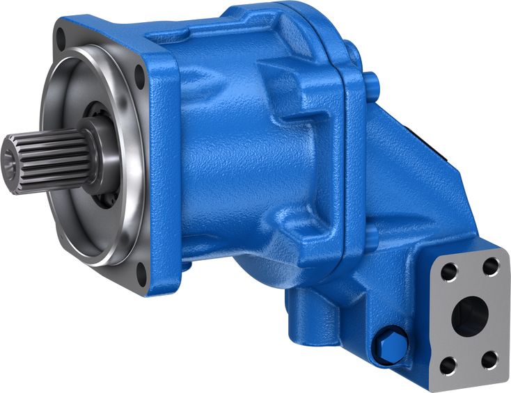
A2FM
Rexroth
三种压力范围,适应不同客户要求与应用。
功率密度很高。
总效率很高。
启动效率高。
坚固的40°斜轴技术。
可选集成冲洗阀。
斜轴式结构。
| 1) | For A2FM onlyN available (pressure range 300 to 350 bar) |
| 2) | Not for A2FMH available (pressure range 450 to 500 bar) |
| 1) | Not available for A2FMH |
Size | 56 | 63 | 80 | 90 | 107 | 45 | 56 | 63 | 80 | 90 | 45 | 56 | 63 | 80 | 90 | |||
Version | A2FMN | A2FMM | A2FMH | |||||||||||||||
Displacement | Vg | cm³ | 56.6 | 63 | 81.7 | 90.5 | 108.8 | 44.9 | 56.6 | 63 | 79.8 | 90.5 | 44.9 | 56.6 | 63 | 79.8 | 90.5 | |
Nominal pressure | pnom | bar | 300 | 300 | 300 | 300 | 300 | 400 | 400 | 400 | 400 | 400 | 450 | 450 | 450 | 450 | 450 | |
Maximum pressure | pmax | bar | 350 | 350 | 350 | 350 | 350 | 450 | 450 | 450 | 450 | 450 | 500 | 500 | 500 | 500 | 500 | |
Maximum speed | nnom 1) | rpm | 3750 | 3750 | 3375 | 3375 | 3000 | 5000 | 5000 | 5000 | 4500 | 4500 | 5000 | 5000 | 5000 | 4500 | 4500 | |
nmax 2) | rpm | 4125 | 4125 | 3700 | 3700 | 3300 | 5500 | 5500 | 5500 | 5000 | 5000 | 5500 | 5500 | 5500 | 5000 | 5000 | ||
Inlet flow | at nnom | qV | l/min | 210 | 236 | 270 | 270 | 321 | 225 | 280 | 315 | 360 | 405 | 225 | 280 | 315 | 360 | 405 |
Torque 3) | at pnom | M | Nm | 270 | 301 | 390 | 432 | 519 | 286 | 360 | 401 | 508 | 576 | 322 | 405 | 451 | 571 | 648 |
Rotary stiffness | c | kNm/rad | 6.83 | 8.09 | 7.94 | 9.84 | 10.9 | 4.52 | 6.83 | 8.09 | 9.09 | 9.84 | 4.52 | 6.83 | 8.09 | 9.09 | 9.84 | |
Moment of inertia for rotary group | JTW | kg·m² | 0.0032 | 0.0032 | 0.0034 | 0.0054 | 0.0061 | 0.0032 | 0.0032 | 0.0032 | 0.0058 | 0.0054 | 0.0032 | 0.0032 | 0.0032 | 0.0058 | 0.0054 | |
Maximum angular acceleration | ɑ | rad/s² | 10000 | 12200 | 19800 | 4500 | 6000 | 5400 | 9000 | 11100 | 4500 | 4500 | 5000 | 8550 | 10500 | 4500 | 4500 | |
Case volume | V | l | 0.6 | 0.6 | 0.6 | 0.65 | 0.65 | 0.6 | 0.6 | 0.6 | 0.65 | 0.65 | 0.6 | 0.6 | 0.6 | 0.65 | 0.65 | |
Weight (approx.) | m | kg | 17 | 17 | 17 | 23 | 23 | 17 | 17 | 17 | 23 | 23 | 17 | 17 | 17 | 23 | 23 | |
| 1) | These values are valid at: - for the optimum viscosity range from vopt = 36 to 16 mm2/s - with hydraulic fluid based on mineral oils |
| 2) | Intermittent maximum speed: overspeed for unload and overhauling processest, t < 5 s and Δp < 150 bar |
| 3) | Torque without radial force, with radial force see table "Permissible radial and axial forces of the drive shafts" |
最低转速 n min 无限制。如要求运动均匀,转速 n min 不得低于 50 rpm。
Determining the operating characteristics | ||
Inlet flow | | [l/min] |
Rotational speed | | [rpm] |
Torque | | [Nm] |
Power | | [kW] |
Key | |
Vg | Displacement per revolution [cm3] |
Δp | Differential pressure [bar] |
n | Rotational speed [rpm] |
ηv | Volumetric efficiency |
ηhm | Hydraulic-mechanical efficiency |
ηt | Total efficiency (ηt = ηv \u2022 ηhm) |
轴向柱塞单元设计用于符合 DIN 51524 的 HLP 矿物油。
开始项目规划之前,应查阅以下数据表,了解液压油的应用说明与要求:
90223: 难燃含水液压液 (HFAE, HFAS, HFB, HFC)
轴向柱塞单元不适合使用 HFA 液压液。
Viscosity | Shaft | Temperature1) | Comment | |
Cold start | νmax ≤ 1600 mm²/s | NBR2) | ϑSt ≥ -40 °C | t ≤ 3 min, without load (p ≤ 50 bar), n ≤ 1000 rpm, |
FKM | ϑSt ≥ -25 °C | |||
Warm-up phase | ν = 400 \u2026 1600 mm²/s | t ≤ 15 min, p ≤ 0.7 \u2022 pnom and n ≤ 0.5 \u2022 nnom | ||
Continuous operation | ν = 10 \u2026 400 mm²/s3) | NBR2) | ϑ ≤ +78 °C | measured at port T |
FKM | ϑ ≤ +103 °C | |||
νopt = 16 \u2026 36 mm²/s | range of optimum operating viscosity and efficiency | |||
Short-term operation | νmin = 7 \u2026 10 mm²/s | NBR2) | ϑ ≤ +78 °C | t ≤ 3 min, p ≤ 0.3 \u2022 pnom measured at port T |
FKM | ϑ ≤ +103 °C |
| 1) | If the specified temperatures cannot be maintained due to extreme operating parameters, please contact us. |
| 2) | Special version, please contact us. |
| 3) | Equates e.g. with the VG 46 a temperature range of +5 °C to +85 °C (see selection diagram) |
为降低轴向柱塞单元中液压油的高温,建议使用冲洗补油压力阀(见“扩展功能和型号”章节)。
Bosch Rexroth 按技术数据表 90235 中的液压油评级方法评估液压油。
以下技术数据表列出了在液压油评级中获得正面评价的液压油:
选择液压油时,应使工作温度范围内的工作黏度处于最佳范围 (ν opt;见选择图)。
更精细的过滤可提高液压油清洁度,从而延长轴向柱塞单元的寿命。
应按 ISO 4406 保持至少 20/18/15 的清洁度等级。
当泄油口处液压油黏度低于 10 mm²/s 时(例如高温短时运行),要求按 ISO 4406 达到至少 19/17/14 的清洁度等级。
例如,在以下情况下,黏度为 10 mm²/s:
Pressure at working port A or B (high-pressure side) | Definition | ||
Nominal pressure | pnom | see table of values | The nominal pressure corresponds to the maximum design pressure. |
Maximum pressure | pmax | see table of values | The maximum pressure corresponds to the maximum operating pressure within the single operating period. The sum of the single operating periods must not exceed the total operating period. |
Single operating period | 10 s | ||
Total operating period | 300 h | ||
Minimum pressure | pHP min | 25 bar | Minimum pressure on high-pressure side (port A or B) required to prevent damage to the axial piston unit. |
Minimum pressure at inlet (pump operating mode) | pE min | see diagram | To prevent damage to the axial piston motor in pump mode (change of high-pressure side with unchanged direction of rotation, e.g. when braking),a minimum pressure must be guaranteed at the working port (inlet). The minimum pressure depends on the rotational speed and displacement of the axial piston unit. |
Total pressure | pSu | 700 bar | The summation pressure is the sum of the pressures at both work ports (A and B). |
Rate of pressure change | Definition | ||
with integrated pressure relief valve | RA max | 9000 bar/s | Maximum permissible rate of pressure build-up and reduction during a pressure change over the entire pressure range. |
without pressure relief valve | RA max | 16000 bar/s | |
Case pressure at port T | Definition | ||
Continuous differential pressure | ΔpT cont | 2 bar | Maximum averaged differential pressure at the shaft seal (case to ambient) |
Pressure peaks | pT peak | 10 bar | t < 0.1 s |
本图仅适用于最佳黏度范围 v opt = 16 至 36 mm 2 /sec..
如不能确保上述条件,请联系我们。
| 1) | Total operating period = t1 + t2 + ... + tn |
Size | 56 | 63 | 80 | 90 | 107 | 45 | 56 | 63 | 80 | 90 | 45 | 56 | 63 | 80 | 90 | |||||||||||||||||||||||||||||||||||||
Version | A2FMN | A2FMM | A2FMH | |||||||||||||||||||||||||||||||||||||||||||||||||
Drive shaft | Code | V8 | S7 | P6 | P8 | V8 | S7 | P8 | V8 | S7 | P8 | P9 | V8 | S7 | P9 | V8 | S7 | P9 | S7 | P6 | V8 | S7 | P6 | P8 | V8 | S7 | P8 | V8 | S7 | P8 | P9 | V8 | S7 | P9 | S7 | P6 | V8 | S7 | P6 | P8 | V8 | S7 | P8 | V8 | S7 | P8 | P9 | V8 | S7 | P9 | ||
⌀ | in | 1 3/8 in | 1 1/4 in | 1 3/8 in | 1 1/4 in | 1 3/8 in | 1 1/4 in | 1 3/8 in | 1 1/4 in | 1 3/8 in | 1 1/4 in | 1 1/4 in | 1 3/8 in | 1 1/4 in | 1 3/8 in | 1 1/4 in | 1 3/8 in | 1 1/4 in | 1 3/8 in | 1 1/4 in | 1 1/4 in | 1 3/8 in | 1 1/4 in | 1 3/8 in | 1 1/4 in | 1 3/8 in | 1 1/4 in | 1 3/8 in | 1 1/4 in | |||||||||||||||||||||||
⌀ | mm | 30 | 35 | 35 | 35 | 40 | 40 | 40 | 30 | 30 | 35 | 35 | 35 | 40 | 40 | 30 | 30 | 35 | 35 | 35 | 40 | 40 | ||||||||||||||||||||||||||||||
Maximum radial force | | Fq max | kN | 6.1 | 6.7 | 6.1 | 6.1 | 7.6 | 7.6 | 6.9 | 8.8 | 9.5 | 8.7 | 7.6 | 9.8 | 9.4 | 9.8 | 11.9 | 9.4 | 10.4 | 7.2 | 7.6 | 8.2 | 9 | 9.5 | 8.1 | 9.2 | 9.5 | 9.2 | 11.7 | 9.4 | 11.6 | 10.2 | 13.1 | 9.4 | 11.5 | 8.1 | 8.6 | 9.2 | 9 | 10.7 | 9.2 | 10.3 | 9.5 | 10.3 | 13.1 | 9.5 | 10.3 | 11.5 | 13.1 | 9.4 | 12.9 |
a | mm | 24 | 24 | 18 | 18 | 24 | 24 | 18 | 24 | 24 | 18 | 18 | 24 | 24 | 20 | 24 | 24 | 20 | 24 | 18 | 24 | 24 | 18 | 18 | 24 | 24 | 18 | 24 | 24 | 20 | 20 | 24 | 24 | 20 | 24 | 18 | 24 | 24 | 18 | 18 | 24 | 24 | 18 | 24 | 24 | 20 | 20 | 24 | 24 | 20 | ||
Permitted torque at Fq max | Tq max | Nm | 267 | 267 | 267 | 267 | 301 | 301 | 301 | 382 | 376 | 382 | 382 | 430 | 372 | 430 | 519 | 372 | 519 | 286 | 286 | 357 | 357 | 357 | 357 | 401 | 376 | 401 | 509 | 373 | 509 | 509 | 573 | 372 | 573 | 322 | 322 | 401 | 357 | 401 | 401 | 451 | 376 | 451 | 573 | 376 | 573 | 573 | 573 | 372 | 645 | |
Permitted differential pressure at Fq max | Δpq max | bar | 300 | 300 | 300 | 300 | 300 | 300 | 300 | 300 | 295 | 300 | 300 | 300 | 260 | 300 | 300 | 215 | 300 | 400 | 400 | 400 | 400 | 400 | 400 | 400 | 375 | 400 | 400 | 293 | 400 | 400 | 400 | 260 | 400 | 450 | 450 | 450 | 400 | 450 | 450 | 450 | 375 | 450 | 450 | 375 | 450 | 450 | 400 | 260 | 450 | |
Maximum axial force, when standstill or in non-pressurized conditions | | + Fax max | N | 0 | 0 | 0 | 0 | 0 | 0 | 0 | 0 | 0 | 0 | 0 | 0 | 0 | 0 | 0 | 0 | 0 | 0 | 0 | 0 | 0 | 0 | 0 | 0 | 0 | 0 | 0 | 0 | 0 | 0 | 0 | 0 | 0 | 0 | 0 | 0 | 0 | 0 | 0 | 0 | 0 | 0 | 0 | 0 | 0 | 0 | 0 | 0 | 0 |
- Fax max | N | 800 | 800 | 800 | 800 | 800 | 800 | 800 | 800 | 800 | 800 | 800 | 1000 | 1000 | 1000 | 1000 | 1000 | 1000 | 800 | 800 | 800 | 800 | 800 | 800 | 800 | 800 | 800 | 1000 | 1000 | 1000 | 1000 | 1000 | 1000 | 1000 | 800 | 800 | 800 | 800 | 800 | 800 | 800 | 800 | 800 | 1000 | 800 | 1000 | 1000 | 1000 | 1000 | 1000 | ||
Maximum axial force, per bar operating pressure | + Fax max | N/bar | 8.7 | 8.7 | 8.7 | 8.7 | 8.7 | 8.7 | 8.7 | 8.7 | 8.7 | 8.7 | 8.7 | 10.6 | 10.6 | 10.6 | 10.6 | 10.6 | 10.6 | 8.7 | 8.7 | 8.7 | 8.7 | 8.7 | 8.7 | 8.7 | 8.7 | 8.7 | 10.6 | 10.6 | 10.6 | 10.6 | 10.6 | 10.6 | 10.6 | 8.7 | 8.7 | 8.7 | 8.7 | 8.7 | 8.7 | 8.7 | 8.7 | 8.7 | 10.6 | 8.7 | 10.6 | 10.6 | 10.6 | 10.6 | 10.6 | |
选择合适的径向力 F q 方向,可减小内部旋转组件作用力对轴承产生的载荷,从而优化轴承寿命。配对齿轮的推荐安装位置取决于旋转方向。示例:
1 | Direction of rotation "counter-clockwise", pressure at port B |
2 | Direction of rotation "clockwise", pressure at port A |
3 | Direction of rotation "bidirectional" |
遵守液压油过滤要求(见“项目规划信息”章节)。
SAE working ports at bottom
Version | Size | D1 | D3 | D4 | D7 | D8 | D9 | D12 | D13 | D14 | D15 | D17 | D18 | D19 | D20 | D25 | D26 | D29 | D33 | D40 | D41 | D42 | D46 | D47 |
mm | mm | mm | mm | mm | mm | mm | mm | mm | mm | mm | mm | mm | mm | mm | mm | mm | mm | mm | mm | mm | mm | mm | ||
| A2FMN | 56 | 127 | 196.7 | 122 | 162 | 20 | 12.7 | 86 | 172.7 | 122 | 172.7 | 30 | 150.2 | 127 | 117.2 | 146 | 146 | 14.3 | 141 | 23.8 | 50.8 | 19 | 75 | 20 |
| 63 | 127 | 196.7 | 122 | 162 | 20 | 12.7 | 86 | 172.7 | 122 | 172.7 | 30 | 150.2 | 127 | 117.2 | 146 | 146 | 14.3 | 141 | 23.8 | 50.8 | 19 | 75 | 20 | |
| 80 | 127 | 196.7 | 122 | 162 | 20 | 12.7 | 86 | 172.7 | 122 | 172.7 | 30 | 150.2 | 127 | 117.2 | 146 | 146 | 14.3 | 141 | 23.8 | 50.8 | 19 | 75 | 20 | |
| 90 | 127 | 222.5 | 148.5 | 162 | 20 | 12.7 | 101.5 | 195.5 | 142 | 195.5 | 30 | 169.5 | 127 | 135 | 146 | 142 | 14.3 | 159 | 27.8 | 57.2 | 25 | 84 | 25 | |
| 107 | 127 | 222.5 | 148.5 | 162 | 20 | 12.7 | 101.5 | 195.5 | 142 | 195.5 | 30 | 169.5 | 127 | 135 | 146 | 142 | 14.3 | 159 | 27.8 | 57.2 | 25 | 84 | 25 | |
| A2FMM | 45 | 127 | 196.7 | 122 | 162 | 20 | 12.7 | 86 | 172.7 | 122 | 172.7 | 30 | 150.2 | 127 | 117.2 | 146 | 146 | 14.3 | 141 | 23.8 | 50.8 | 19 | 75 | 20 |
| 56 | 127 | 196.7 | 122 | 162 | 20 | 12.7 | 86 | 172.7 | 122 | 172.7 | 30 | 150.2 | 127 | 117.2 | 146 | 146 | 14.3 | 141 | 23.8 | 50.8 | 19 | 75 | 20 | |
| 63 | 127 | 196.7 | 122 | 162 | 20 | 12.7 | 86 | 172.7 | 122 | 172.7 | 30 | 150.2 | 127 | 117.2 | 146 | 146 | 14.3 | 141 | 23.8 | 50.8 | 19 | 75 | 20 | |
| 80 | 127 | 222.5 | 148.5 | 162 | 20 | 12.7 | 101.5 | 195.5 | 142 | 195.5 | 30 | 169.5 | 127 | 135 | 146 | 142 | 14.3 | 159 | 27.8 | 57.2 | 25 | 84 | 25 | |
| 90 | 127 | 222.5 | 148.5 | 162 | 20 | 12.7 | 101.5 | 195.5 | 142 | 195.5 | 30 | 169.5 | 127 | 135 | 146 | 142 | 14.3 | 159 | 27.8 | 57.2 | 25 | 84 | 25 | |
| A2FMH | 45 | 127 | 172.7 | 122 | 162 | 20 | 12.7 | 86 | 172.7 | 122 | 172.7 | 30 | 150.2 | 127 | 117.2 | 146 | 146 | 14.3 | 141 | 23.8 | 50.8 | 19 | 75 | 20 |
| 56 | 127 | 172.7 | 122 | 162 | 20 | 12.7 | 86 | 172.7 | 122 | 172.7 | 30 | 150.2 | 127 | 117.2 | 146 | 146 | 14.3 | 141 | 23.8 | 50.8 | 19 | 75 | 20 | |
| 63 | 127 | 172.7 | 122 | 162 | 20 | 12.7 | 86 | 172.7 | 122 | 172.7 | 30 | 150.2 | 127 | 117.2 | 146 | 146 | 14.3 | 141 | 23.8 | 50.8 | 19 | 75 | 20 | |
| 80 | 127 | 162 | 20 | 12.7 | 101.5 | 195.5 | 142 | 195.5 | 30 | 169.5 | 127 | 135 | 146 | 142 | 14.3 | 159 | 27.8 | 57.2 | 25 | 84 | 25 | |||
| 90 | 127 | 162 | 20 | 12.7 | 101.5 | 195.5 | 142 | 195.5 | 30 | 169.5 | 127 | 135 | 146 | 142 | 14.3 | 159 | 27.8 | 57.2 | 25 | 84 | 25 |
SAE working ports at side, opposite
Version | Size | D1 | D3 | D4 | D7 | D8 | D9 | D12 | D13 | D14 | D15 | D17 | D18 | D19 | D20 | D25 | D26 | D29 | D33 | D40 | D41 | D42 | D46 | D47 |
mm | mm | mm | mm | mm | mm | mm | mm | mm | mm | mm | mm | mm | mm | mm | mm | mm | mm | mm | mm | mm | mm | mm | ||
| A2FMN | 56 | 127 | 196.7 | 122 | 162 | 20 | 12.7 | 86 | 172.7 | 122 | 172.7 | 30 | 150.2 | 127 | 117.2 | 146 | 146 | 14.3 | 141 | 23.8 | 50.8 | 19 | 75 | 20 |
| 63 | 127 | 196.7 | 122 | 162 | 20 | 12.7 | 86 | 172.7 | 122 | 172.7 | 30 | 150.2 | 127 | 117.2 | 146 | 146 | 14.3 | 141 | 23.8 | 50.8 | 19 | 75 | 20 | |
| 80 | 127 | 196.7 | 122 | 162 | 20 | 12.7 | 86 | 172.7 | 122 | 172.7 | 30 | 150.2 | 127 | 117.2 | 146 | 146 | 14.3 | 141 | 23.8 | 50.8 | 19 | 75 | 20 | |
| 90 | 127 | 222.5 | 148.5 | 162 | 20 | 12.7 | 101.5 | 195.5 | 142 | 195.5 | 30 | 169.5 | 127 | 135 | 146 | 142 | 14.3 | 159 | 27.8 | 57.2 | 25 | 84 | 25 | |
| 107 | 127 | 222.5 | 148.5 | 162 | 20 | 12.7 | 101.5 | 195.5 | 142 | 195.5 | 30 | 169.5 | 127 | 135 | 146 | 142 | 14.3 | 159 | 27.8 | 57.2 | 25 | 84 | 25 | |
| A2FMM | 45 | 127 | 196.7 | 122 | 162 | 20 | 12.7 | 86 | 172.7 | 122 | 172.7 | 30 | 150.2 | 127 | 117.2 | 146 | 146 | 14.3 | 141 | 23.8 | 50.8 | 19 | 75 | 20 |
| 56 | 127 | 196.7 | 122 | 162 | 20 | 12.7 | 86 | 172.7 | 122 | 172.7 | 30 | 150.2 | 127 | 117.2 | 146 | 146 | 14.3 | 141 | 23.8 | 50.8 | 19 | 75 | 20 | |
| 63 | 127 | 196.7 | 122 | 162 | 20 | 12.7 | 86 | 172.7 | 122 | 172.7 | 30 | 150.2 | 127 | 117.2 | 146 | 146 | 14.3 | 141 | 23.8 | 50.8 | 19 | 75 | 20 | |
| 80 | 127 | 222.5 | 148.5 | 162 | 20 | 12.7 | 101.5 | 195.5 | 142 | 195.5 | 30 | 169.5 | 127 | 135 | 146 | 142 | 14.3 | 159 | 27.8 | 57.2 | 25 | 84 | 25 | |
| 90 | 127 | 222.5 | 148.5 | 162 | 20 | 12.7 | 101.5 | 195.5 | 142 | 195.5 | 30 | 169.5 | 127 | 135 | 146 | 142 | 14.3 | 159 | 27.8 | 57.2 | 25 | 84 | 25 | |
| A2FMH | 45 | 127 | 172.7 | 122 | 162 | 20 | 12.7 | 86 | 172.7 | 122 | 172.7 | 30 | 150.2 | 127 | 117.2 | 146 | 146 | 14.3 | 141 | 23.8 | 50.8 | 19 | 75 | 20 |
| 56 | 127 | 172.7 | 122 | 162 | 20 | 12.7 | 86 | 172.7 | 122 | 172.7 | 30 | 150.2 | 127 | 117.2 | 146 | 146 | 14.3 | 141 | 23.8 | 50.8 | 19 | 75 | 20 | |
| 63 | 127 | 172.7 | 122 | 162 | 20 | 12.7 | 86 | 172.7 | 122 | 172.7 | 30 | 150.2 | 127 | 117.2 | 146 | 146 | 14.3 | 141 | 23.8 | 50.8 | 19 | 75 | 20 | |
| 80 | 127 | 162 | 20 | 12.7 | 101.5 | 195.5 | 142 | 195.5 | 30 | 169.5 | 127 | 135 | 146 | 142 | 14.3 | 159 | 27.8 | 57.2 | 25 | 84 | 25 | |||
| 90 | 127 | 162 | 20 | 12.7 | 101.5 | 195.5 | 142 | 195.5 | 30 | 169.5 | 127 | 135 | 146 | 142 | 14.3 | 159 | 27.8 | 57.2 | 25 | 84 | 25 |
| 1) | Involute spline according to ANSI B92.1a, 30° pressure angle, flat root, side fit, tolerance class 5 |
| 2) | Thread according to ASME B1.1 |
| 3) | Center bore according to DIN 332 (thread according to DIN 13) |
| 4) | For sizes to 63 and size 80 pressure range "N" |
| 5) | For sizes from 80, excluding size 80 pressure range "N" |
Size | 56 | 63 | 80 | 90 | 107 | 45 | 56 | 63 | 80 | 90 | 45 | 56 | 63 | 80 | 90 | ||
Version | A2FMN | A2FMM | A2FMH | ||||||||||||||
A, B | Working port | Size | 3/4 in | 1 in | 3/4 in | 1 in | 3/4 in | 1 in | |||||||||
Standard | Dimensions according to SAE J518 | ||||||||||||||||
Fastening thread | 3/8-16UNC-2B; 21 mm deep | 7/16-14UNC-2B; 19 mm deep | 3/8-16UNC-2B; 21 mm deep | 7/16-14UNC-2B; 19 mm deep | 3/8-16UNC-2B; 21 mm deep | 7/16-14UNC-2B; 19 mm deep | |||||||||||
State on delivery | With protective cover (must be connected) | ||||||||||||||||
T1 | Drain port | Size | 3/4-16UNF-2B; 15 mm deep | 7/8-14UNF-2B; 17 mm deep | 3/4-16UNF-2B; 15 mm deep | 7/8-14UNF-2B; 17 mm deep | 3/4-16UNF-2B; 15 mm deep | 7/8-14UNF-2B; 17 mm deep | |||||||||
Standard 1) | ISO 11926 | ||||||||||||||||
State on delivery | Plugged (observe installation instructions) | ||||||||||||||||
T2 | Drain port | Size | 3/4-16UNF-2B; 15 mm deep | 7/8-14UNF-2B; 17 mm deep | 3/4-16UNF-2B; 15 mm deep | 7/8-14UNF-2B; 7 mm deep | 3/4-16UNF-2B; 15 mm deep | 7/8-14UNF-2B; 17 mm deep | |||||||||
Standard 1) | ISO 11926 | ||||||||||||||||
State on delivery | With protective cover (observe installation instructions) | ||||||||||||||||
| 1) | The spot face can be deeper than specified in the appropriate standard. |
参见下列示例 1 至 8。
其他安装位置可按要求提供。建议安装位置:1 和 2。
注意
安装位置 4 和 8,即“轴朝上”时,需要设置排气口 R(订购时请以文字注明,特殊版本)。
油箱下方安装,是指轴向柱塞单元安装在油箱外部、最低液面以下。
油箱上方安装,是指轴向柱塞单元安装在油箱最低液面以上。
安装位置 8(传动轴朝上)的建议:在泄油管路中设置单向阀,开启压力为 0,5 bar,可防止泵壳内油液排空。
Key | |
F | Filling / Air bleeding |
R | Air bleed port |
T1, T2 | Drain port |
ht min | Minimum required immersion depth (200 mm) |
hmin | Minimum required spacing to reservoir bottom (100 mm) |