

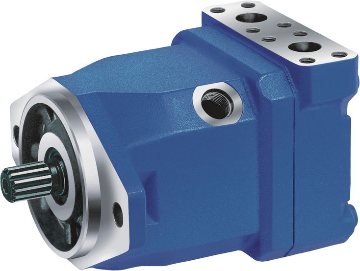

采用成熟的A10旋转组件技术。
获准用于高转速。
使用寿命长。
功率密度高。
运行噪声低。
可选集成防气蚀阀,例如用于风扇驱动。
可选转速传感器。
斜盘式结构。
采用成熟的A10旋转组件技术。
获准用于高转速。
使用寿命长。
功率密度高。
运行噪声低。
可选集成防气蚀阀,例如用于风扇驱动。
可选转速传感器。
斜盘式结构。
| 1) | Only necessary in conjunction with valve configuration "2" (integrated anti cavitation valve) |
Size | 18 | 23 | 28 | 37 | 45 | 58 | 63 | |||
Displacement | Vg | cm³ | 18 | 23.5 | 28.5 | 36.7 | 44.5 | 58 | 63.1 | |
Nominal pressure | pnom | bar | 280 | 280 | 280 | 280 | 280 | 280 | 280 | |
Maximum pressure | pmax | bar | 350 | 350 | 350 | 350 | 350 | 350 | 350 | |
Maximum speed 1) | nnom | rpm | 4200 | 4900 | 4700 | 4200 | 4000 | 3600 | 3400 | |
Inlet flow | at nnom | qV | l/min | 76 | 115 | 134 | 154 | 178 | 209 | 215 |
Power | at nnom and pnom | P | kW | 35.3 | 53.6 | 62.5 | 71.8 | 83.1 | 97.4 | 100.1 |
Starting torque | at nnom and pnom | M0 | Nm | 67.5 | 75 | 105 | 125 | 170 | 205 | 230 |
Torque | at pnom | M | Nm | 80 | 105 | 127 | 163 | 198 | 258 | 281 |
Rotary stiffness | Drive shaft R | c | kNm/rad | 14.835 | 28.478 | 28.478 | 46.859 | 46.859 | 80.59 | 80.59 |
Drive shaft W | c | kNm/rad | 38.489 | 38.489 | 60.907 | 60.907 | ||||
Drive shaft C | c | kNm/rad | 18.662 | 30.017 | 30.017 | 46.546 | 46.546 | 87.667 | 87.667 | |
Moment of inertia for rotary group | JTW | kg·m² | 0.00093 | 0.0017 | 0.0017 | 0.0033 | 0.0033 | 0.0056 | 0.0056 | |
Maximum angular acceleration | ɑ | rad/s² | 6800 | 5500 | 5500 | 4000 | 4000 | 3300 | 3300 | |
Case volume | V | l | 0.15 | 0.6 | 0.6 | 0.7 | 0.7 | 0.8 | 0.8 | |
Weight (approx.) | m | kg | 6.5 | 12 | 12 | 17 | 17 | 22 | 22 | |
| 1) | At least 18 bar required at low pressure side |
表中数值为理论值,未考虑效率和公差,并已取整。
超过允许最大值或低于允许最小值,可能导致轴向柱塞单元功能丧失、工作寿命缩短或完全损坏。建议通过试验或计算/仿真检验载荷,并与允许值进行比较。
Determining the operating characteristics | ||
Inlet flow | | [l/min] |
Rotational speed | | [rpm] |
Torque | | [Nm] |
Power | | [kW] |
Key | |
Vg | Displacement per revolution [cm3] |
Δp | Differential pressure [bar] |
n | Rotational speed [rpm] |
ηv | Volumetric efficiency |
ηhm | Hydraulic-mechanical efficiency |
ηt | Total efficiency (ηt = ηv \u2022 ηhm) |
轴向柱塞单元设计用于符合 DIN 51524 的 HLP 矿物油。
开始项目规划之前,应查阅以下数据表,了解液压油的应用说明与要求:
使用环境友好型液压油时,请咨询我们。
| Viscosity | Shaft | Temperature1) | Comment |
Cold start | νmax ≤ 1600 mm²/s | NBR2) | ϑSt ≥ -40 °C | t ≤ 1 min, without load (p ≤ 30 bar), n ≤ 1000 rpm, |
FKM | ϑSt ≥ -25 °C | |||
Warm-up phase | ν = 400 \u2026 1600 mm²/s |
| t ≤ 15 min, p ≤ 0.7 \u2022 pnom and n ≤ 0.5 \u2022 nnom | |
Continuous operation | ν = 10 \u2026 400 mm²/s3) | NBR2) | ϑ ≤ +78 °C | measured at port L |
FKM | ϑ ≤ +103 °C | |||
νopt = 16 \u2026 36 mm²/s | range of optimum operating viscosity and efficiency | |||
Short-term operation | νmin = 7 \u2026 10 mm²/s | NBR2) | ϑ ≤ +78 °C | t ≤ 3 min, p ≤ 0.3 \u2022 pnom measured at port L |
FKM | ϑ ≤ +103 °C |
| 1) | If the specified temperatures cannot be maintained due to extreme operating parameters, please contact us. |
| 2) | Special version, please contact us. |
| 3) | Equates e.g. with the VG 46 a temperature range of +5 °C to +85 °C (see selection diagram) |
Bosch Rexroth 按技术数据表 90235 中的液压油评级方法评估液压油。
以下技术数据表列出了在液压油评级中获得正面评价的液压油:
选择液压油时,应使工作温度范围内的工作黏度处于最佳范围 (ν opt;见选择图)。
更精细的过滤可提高液压油清洁度,从而延长轴向柱塞单元的寿命。
应按 ISO 4406 保持至少 20/18/15 的清洁度等级。
当泄油口处液压油黏度低于 10 mm²/s 时(例如高温短时运行),要求按 ISO 4406 达到至少 19/17/14 的清洁度等级。
例如,在以下情况下,黏度为 10 mm²/s:
HLP 32,温度为 73°C
HLP 46,温度为 85°C
Pressure at working port A or B | Definition | ||
Nominal pressure | pnom | see table of values | The nominal pressure corresponds to the maximum design pressure. |
Maximum pressure | pmax | see table of values | The maximum pressure corresponds to the maximum operating pressure within the single operating period. The sum of the single operating periods must not exceed the total operating period. |
Single operating period | 2.5 s | ||
Total operating period | 300 h | ||
Minimum pressure (high-pressure side) | pHP min | 10 bar | Minimum pressure on high- or low-pressure side (port A or B) required to prevent damage to the axial piston unit. |
Minimum pressure (low-pressure side) | pLP min | see diagram "Permissible rotational speed in relation to outlet pressure" | |
Rate of pressure change | Definition | ||
Rate of pressure change | RA max | 16000 bar/s | Maximum permissible rate of pressure build-up and reduction during a pressure change over the entire pressure range. |
Case pressure at port L | Definition | ||
Motor operation mode | pL max | 4 bar absolute | Maximum permissible case pressure measured at port L or L1 |
Pump operating mode | pL max | 2 bar absolute | |
工作压力范围适用于矿物油基液压油。其他液压液的适用值请联系我们。
| 1) | Total operating period = t1 + t2 + ... + tn |
Direction of rotation, viewed on drive shaft | |
clockwise | counter-clockwise |
A to B | B to A |
Size | 18 | 23 | 28 | 37 | 45 | 58 | 63 | ||||
Splined shaft | Code | R | R, W | R, W | R, W | R, W | R, W | R, W | |||
Tapered shaft | Code | C | C | C | C | C | C | C | |||
Maximum radial force | | | Fq max | N | 350 | 1200 | 1200 | 1500 | 1500 | 1700 | 1700 |
Maximum axial force | | ± Fax max | N | 700 | 1000 | 1000 | 1500 | 1500 | 2000 | 2000 | |
| 1) | Flange ISO 3019-1 |
| 1) | Flange ISO 3019-1 |
| 1) | Toothing data valid for basic number of teeth 48 |
Size | 23 | 28 | ||
A, B | Working port | Size | 3/4 in | |
Standard | Dimensions according to SAE J518 | |||
Fastening thread 1) | M10 × 1.5; 17 mm deep | |||
State on delivery | With protective cover (must be connected) | |||
A, B | Working port | Size | M27 × 2; 16 mm deep | |
Standard | DIN 3852 | |||
State on delivery | With protective cover (must be connected) | |||
L | Drain port | Size | 3/4-16 UNF-2B; 11 mm deep | |
Standard 2) | ISO 11926 | |||
State on delivery 3) | With protective cover (observe installation instructions) | |||
L1 | Drain port | Size | 3/4-16 UNF-2B; 11 mm deep | |
Standard 2) | ISO 11926 | |||
State on delivery 3) | Plugged (observe installation instructions) | |||
| 1) | Thread according to DIN 13 |
| 2) | The spot face can be deeper than specified in the appropriate standard. |
| 3) | Unless otherwise specified. Other layouts on request. |
| 1) | Flange ISO 3019-1 |
| 1) | Flange ISO 3019-1 |
| 1) | Toothing data valid for basic number of teeth 48 |
Size | 37 | 45 | ||
A, B | Working port | Size | 3/4 in | |
Standard | Dimensions according to SAE J518 | |||
Fastening thread 1) | M10 × 1.5; 17 mm deep | |||
State on delivery | With protective cover (must be connected) | |||
A, B | Working port | Size | M27 × 2; 16 mm deep | |
Standard | DIN 3852 | |||
State on delivery | With protective cover (must be connected) | |||
L | Drain port | Size | 7/8-14 UNF-2B; 13 mm deep | |
Standard 2) | ISO 11926 | |||
State on delivery 3) | With protective cover (observe installation instructions) | |||
L1 | Drain port | Size | 7/8-14 UNF-2B; 13 mm deep | |
Standard 2) | ISO 11926 | |||
State on delivery 3) | Plugged (observe installation instructions) | |||
| 1) | Thread according to DIN 13 |
| 2) | The spot face can be deeper than specified in the appropriate standard. |
| 3) | Unless otherwise specified. Other layouts on request. |
| 1) | Flange ISO 3019-1 |
| 1) | Flange ISO 3019-1 |
| 1) | Toothing data valid for basic number of teeth 48 |
Size | 58 | 63 | ||
A, B | Working port | Size | 3/4 in | |
Standard | Dimensions according to SAE J518 | |||
Fastening thread 1) | M10 × 1.5; 17 mm deep | |||
State on delivery | With protective cover (must be connected) | |||
A, B | Working port | Size | M27 × 2; 16 mm deep | |
Standard | DIN 3852 | |||
State on delivery | With protective cover (must be connected) | |||
L | Drain port | Size | 7/8-14 UNF-2B; 13 mm deep | |
Standard 2) | ISO 11926 | |||
State on delivery 3) | With protective cover (observe installation instructions) | |||
L1 | Drain port | Size | 7/8-14 UNF-2B; 13 mm deep | |
Standard 2) | ISO 11926 | |||
State on delivery 3) | Plugged (observe installation instructions) | |||
| 1) | Thread according to DIN 13 |
| 2) | The spot face can be deeper than specified in the appropriate standard. |
| 3) | Unless otherwise specified. Other layouts on request. |
调试和运行期间,轴向柱塞单元必须充满液压油并排尽空气。较长时间停机后也必须注意这一点,因为单元内的油液可能经液压管路流回油箱。
壳体内的泄油必须经位置最高的可用泄油口(L、L 1)引至油箱。
多个单元共用一条泄油管路时,必须确保不超过各单元相应的壳体压力。共用泄油管路的尺寸必须保证,在任何运行条件下,尤其是冷启动时,所有连接单元的最大允许壳体压力均不会被超过。如果无法满足,必须根据需要敷设独立的回油管路。
为获得较低的噪声,应使用弹性元件将所有连接管路解耦,并避免采用油箱上方安装。
在任何运行条件下,泄油管路都必须接入油箱最低液面以下。
参见下列示例 1 至 4。
其他安装位置可按要求提供。建议安装位置:1 和 2。
油箱下方安装,是指轴向柱塞单元安装在油箱外部、最低液面以下。
Installation position | Air bleeding | Filling |
1 | \u2012 | L1 |
2 | \u2012 | L |
油箱上方安装,是指轴向柱塞单元安装在油箱最低液面以上。
Installation position | Air bleeding | Filling |
3 | F | L1 (F) |
4 | F | L (F) |
Key | |
F | Filling / Air bleeding |
L, L2 | Drain port |
SB | Baffle (baffle plate) |
A, B | Working port |
接口 F 属于外部管路的一部分,必须由客户设置,以便简化充油与排气。
轴向柱塞单元设计用于开式和闭式回路。
轴向柱塞单元的项目规划、安装和调试,必须由具备资质的专业人员参与。
使用轴向柱塞单元前,请完整、仔细地阅读相应操作手册。必要时可向 Bosch Rexroth 索取。
最终确定设计前,请索取具有约束力的安装图。
必须遵守规定的数据及说明。
防锈保护:我们的轴向柱塞单元标准供货时,提供最长 12 个月的防锈保护。如需更长的保护时间,最长可达 24 个月,请在订购时以文字注明。上述保护时间仅适用于最佳储存条件;相关条件的详细说明参见数据表 90312 或操作手册。
液压系统中必须设置溢流阀。
必须遵守操作手册中有关连接螺纹及其他螺纹接头拧紧力矩的说明。
必须遵守操作手册中有关油口螺纹及其他螺纹连接拧紧力矩的规定。
油口和安装螺纹按允许的最大压力 p max 设计,参见操作手册。机器或系统制造商必须确保连接元件及管路,在必要安全系数下满足规定的运行条件,包括压力、流量、液压油及温度。
工作油口和功能油口仅用于连接液压管路。