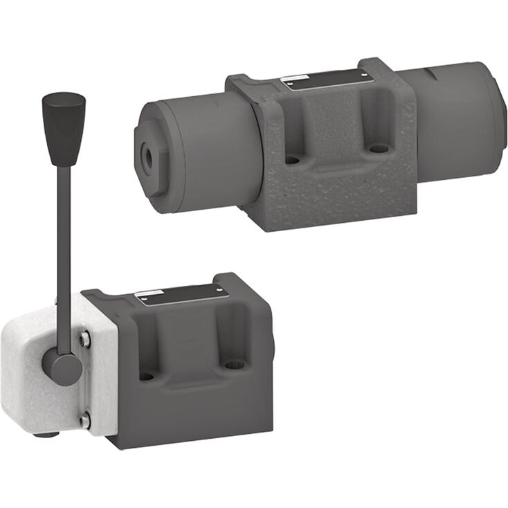
4WE 10 D5X/OFEG24N9K4/M
Rexroth
R983030770
三位四通、二位四通或二位三通型式。
油口布置符合ISO 4401-05-04-0-05。
驱动方式:手柄。
WMM型阀为手动驱动的滑阀换向阀。
用于控制液流的启动、停止及方向。
换向阀主要由阀体(1)、驱动装置(2.1,手柄)、控制阀芯(3)以及一个或两个复位弹簧(4)组成。
断电时,复位弹簧(4)使控制阀芯(3)保持中位或初始位置,“O”版本除外。
通过相应驱动方式,将控制阀芯(3)移至所需阀位。
4WMM 10 E5X/...型。
节流插芯。
若运行条件导致切换过程中出现超过阀性能极限的流量,则必须使用节流插芯。
01 | 02 | 03 | 04 | 05 | 06 | 07 | 08 | 09 | 10 | 11 | ||
WMM | 10 | 5X | / | / | – | * |
01 | 3 main ports | 3 | ||
4 main ports | 4 | |||
Types of actuation | ||||
02 | Manually: hand lever | WMM | ||
03 | Size 10 | 10 | ||
04 | Symbols e. g. C, E, EA, EB, etc.; for the possible version, see Symbols and Types of actuation | |||
05 | Component series 50 … 59 (50 … 59: unchanged installation and connection dimensions) | 5X | ||
06 | With spring return | no code | ||
With detent | F | |||
Corrosion protection | ||||
07 | Standard corrosion protection | no code | ||
Improved corrosion protection (720 h salt spray test according to EN ISO 9227) | J4 | |||
Throttle insert1) | ||||
08 | Without throttle insert | no code | ||
With throttle insert: | ||||
Connection | Throttle Ø in mm | |||
0,8 mm | 1,0 mm | 1,2 mm | ||
P | B08 | B10 | B12 | |
A | H08 | H10 | H12 | |
B | R08 | R10 | R12 | |
A and B | N08 | N10 | N12 | |
T 2) | X08 | X10 | X12 | |
Further throttle insert diameters upon request. | ||||
Seal material | ||||
09 | NBR seals | M | ||
FKM seals | V | |||
Seals for HFC hydraulic fluids | MH | |||
Observe compatibility of seals with hydraulic fluid used. | ||||
Pilot oil port | ||||
10 | Whitworth pipe thread G1/4 | ‒ | ||
11 | Further details in the plain text | * | ||
| 1) When the admissible valve performance limit is exceeded, throttle inserts are to be installed (see Performance limits). | |
| 2) When throttle inserts are used in channel T, the pressure in the working ports and in case of connection to the tank chambers must not exceed 210 bar. |
Size | 10 | ||
Weight | Valve with one actuation cylinder | kg | 3.6 |
Valve with two actuation cylinders | kg | 3.6 | |
Operating force | with detent "F" | N | 30 … 40 |
With spring return | N | 18 … 20 | |
Installation position | any | ||
Ambient temperature range | NBR seals | °C | -20 … +70 |
FKM seals | °C | -15 … +70 | |
Storage temperature range | °C | -20 … +50 | |
Size | 10 | ||
Maximum operating pressure | Port P | bar | 350 |
Port A | bar | 350 | |
Port B | bar | 350 | |
Port T 1) | bar | 210 | |
Maximum flow | l/min | 160 | |
Hydraulic fluid | see table | ||
Hydraulic fluid temperature range 2) | NBR seals | °C | -20 … +80 |
FKM seals | °C | -15 … +80 | |
Viscosity range | mm²/s | 2.8 … 500 | |
Maximum admissible degree of contamination of the hydraulic fluid 3) | Class 20/18/15 according to ISO 4406 (c) | ||
| 1) | With symbols A or B, port T must be used as leakage oil connection if the operating pressure exceeds the admissible tank pressure. |
| 2) | at the valve working ports of the valve |
| 3) | The cleanliness classes specified for the components must be adhered to in hydraulic systems. Effective filtration prevents faults and simultaneously increases the life cycle of the components. For the selection of the filters, see www.boschrexroth.com/filter. |
Hydraulic fluid | Classification | Suitable sealing materials | Standards | |
Mineral oils and related hydrocarbons | HL, HLP, HLPD, HVLP, HVLPD | NBR, FKM | DIN 51524 | |
Bio-degradable | Insoluble in water | HETG | NBR, FKM | VDMA 24568 |
HEES | FKM | |||
Soluble in water | HEPG | FKM | VDMA 24568 | |
Containing water | Water-free | HFDU, HFDR | FKM | ISO 12922 |
Containing water | HFC (Fuchs Hydrotherm 46M, Petrofer Ultra Safe 620) |
NBR
| ISO 12922 | |
Important information on hydraulic fluids!
Flame-resistant – containing water:
| ||||
Dimensions in mm
Dimensions in mm
1 | Valves with 2 spool positions, symbol B and .B |
2 | Valves with 2 switching positions, symbol A, C, D .A |
3 | Valves with 3 switching positions |
4 | Cover and hand lever |
5 | Name plate |
6 | Identical seal rings for port A, B, P, TA, TB |
7 | Additional port TB can optionally be used |
8 | Porting pattern according to ISO 4401-05-04-0-05 |
Notices!
Deviating from ISO 4401, port T is called TA and port T1 is called TB in this data sheet.
For valves with 2 switching positions and symbols B and .B, the hand lever is installed on valve side B.
The dimensions are nominal dimensions which are subject to tolerances.