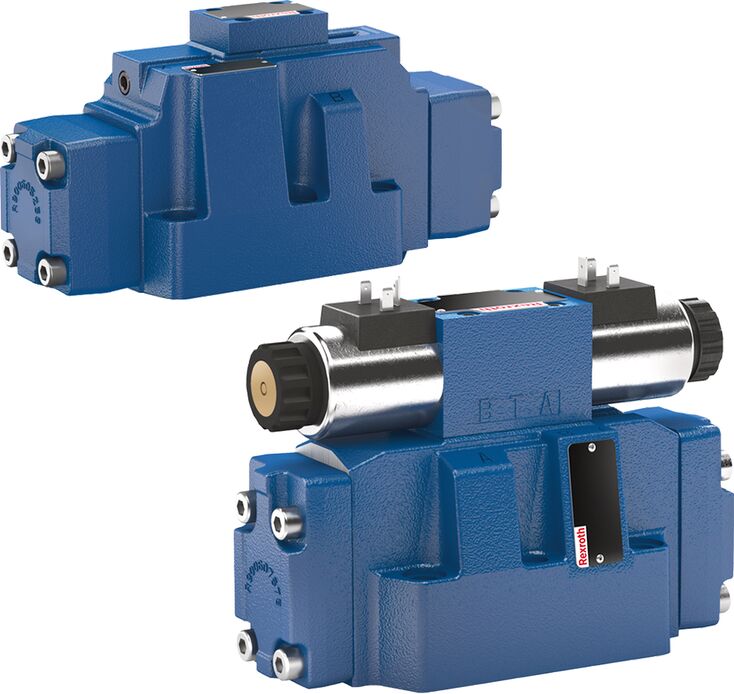
4WEH 16 J7X/6HG24N9ETK4/B10
Rexroth
R901272537
三位四通、二位四通或二位三通型式。
驱动方式可采用内部或外部先导控制:WEH型为电液驱动,WH型为液压驱动。
用于底板安装。
油口布置符合NFPA T3.5.1 R2-2002。
可采用弹簧或压力对中,以及弹簧端位或液压端位。
可选湿式直流或交流电磁铁。
电气连接可采用独立连接或集中连接。
可选版本包括手动应急操作、切换时间调节、主阀P通道预紧阀,以及行程设定和/或阀芯位置监测。
WEH型阀为电液驱动的滑阀换向阀,控制液流启动、停止及方向。主要由带阀体(1)的主阀、主阀芯(2)、一个或两个复位弹簧(3.1)、(3.2),以及带一个或两个电磁铁“a”(5.1)和/或“b”(5.2)的先导阀(4)组成。
为确保正常工作,必须正确排出液压系统内的空气。
对于三位阀,主阀中的主阀芯(2)由两根弹簧保持在零位或初始位置;对于二位阀,则由加压和弹簧共同保持。在初始位置,两个弹簧腔(6)和(8)经先导控制阀(4)无压接回油箱。先导油经控制油路(7)供给先导控制阀,可采用内部供油或外部供油(外部通过 X 口)。操纵先导控制阀时,例如给电磁铁“a”通电,先导阀芯(10)向左移动,使弹簧腔(8)承受先导压力,弹簧腔(6)则仍处于无压状态。先导压力作用于主阀芯(2)的左侧,克服弹簧(3.1)的作用使其移动,从而在主阀中接通 P 至 B、A 至 T。
电磁铁断电后,先导阀芯(10)返回初始位置,脉冲阀芯除外。弹簧腔(8)卸压至油箱。先导回油可采用内部方式(经 T 通道)或外部方式(经 Y 通道)。可选的手动应急操作装置(9)允许在电磁铁未通电时移动先导阀芯(10)。
注意:
即使阀垂直安装,在无先导压力时,弹簧腔(6)、(8)内的复位弹簧(3.1)、(3.2)也可使主阀芯(2)保持中位。
由于结构原理所限,阀存在固有的内泄漏,且内泄漏可能在使用周期内增加。
WH型阀是液压驱动的滑阀换向阀,控制液流启动、停止及方向。主要由阀体(1)、主阀芯(2)、弹簧复位或对中版本中的一个或两个复位弹簧(3.1)、(3.2),以及转接板(11)组成。
主阀芯(2)由压力直接驱动,通过弹簧或压力保持零位或初始位置。先导油供油与回油均为外部方式,参见“先导油供油”。
阀芯采用弹簧对中的三位四通换向阀
该版本中,两个复位弹簧(3.1)、(3.2)使主阀芯(2)保持零位。通过转接板(11),弹簧腔(6)与Y口相通,弹簧腔(8)与X口相通。
向主阀芯(2)两个端面之一施加先导压力时,阀芯移向相应阀位,接通所需油口。当受压端面卸压时,对侧弹簧使阀芯返回零位或初始位置。
主阀芯采用压力对中的三位四通换向阀
主阀中的主阀芯(2)通过两端面受压保持零位。一个对中衬套(12)抵靠阀体并确定阀芯位置。释放一个端面的压力后,主阀芯(2)移向相应阀位。
已卸压的阀芯端面将回流先导油经先导控制阀排至外部Y通道。
注意:
该版本的弹簧(3.1)、(3.2)不具有复位功能,仅在无压且水平安装时,使主阀芯(2)保持中位。
1 | Plug screw M6 according to DIN 906, wrench size 3 - Pilot oil return |
2 | Plug screw M6 according to DIN 906, wrench size 3 – pilot oil supply |
3 | Plug screw M12 x 1.5 according DIN 906, wrench size 6 |
Pilot oil supply | Pilot oil return | ||
External | 2, 3 closed | External | 1 closed |
Internal | 2, 3 open | Internal | 1 open |
WH…型。
先导油通过X、Y通道实现外部供油及回油。
WEH...型。
先导油通过X通道,由独立压力源从外部供给。
先导油经Y通道外部回油至油箱。
WEH…E…型。
先导油由主阀P通道内部供给,参见技术参数。
先导油经Y通道外部回油至油箱,底板中的X口封闭。
WEH…ET…型。
先导油由主阀P通道内部供给。
先导油经T通道内部回油至油箱,底板中的X口及Y口封闭。
WEH…T…型。
先导油通过X通道,由独立压力源从外部供给。
先导油经T通道内部回油至油箱,底板中的Y口封闭。
节流插芯。
若需限制先导阀P通道的先导供油量,必须使用节流插芯(5),并将其装入先导阀P通道。
4 | Pilot control valve |
5 | Main valve |
6 | Throttle insert |
注意事项:
先导油供油方式只能由获授权的专业人员或在工厂中改动。
外部先导供油 X 或外部回油 Y:
必须遵守先导控制阀允许的最大运行参数,参见样本23178。
最大先导压力:请遵守技术参数中的规定。
内部先导供油(“ET”和“E”型):
最小先导压力:请遵守技术参数中的规定。
为防止出现不允许的高压力峰值,必须在先导控制阀的 P 口安装“B10”节流插装件。
采用“H”型结构时,还需要配置减压阀“D3”,参见切换时间调节。
01 | 02 | 03 | 04 | 05 | 06 | 07 | 08 | 09 | 10 | 11 | 12 | 13 | 14 | 15 | 16 | 17 | 18 | 19 | 20 | 21 | 22 | ||
/ | / | * |
01 | Up to 4100 psi | no code |
Up to 5100 psi | H- | |
Main ports | ||
02 | 3-way version | 3 |
4-way version | 4 | |
Type of actuation | ||
03 | Hydraulic | WH |
Electro-hydraulic | WEH | |
Size | ||
04 | NG10 | 10 |
NG16 | 16 | |
NG25 (version "W.H 22") | 22 | |
NG25 (version "W.H 25") | 25 | |
Size 32 | 32 | |
Spool return in the main valve | ||
05 | By means of springs | no code |
Hydraulic 1) | H | |
06 | Symbols; for the possible version, see "Symbols/Circuit diagrams" | |
Component series | ||
07 | Component series 40 … 49 (40 … 49: unchanged installation and connection dimension) – NG10 | 4X |
Component series 60 … 69 (60 … 69: unchanged installation and connection dimension) – NG25 ("W.H 25") and NG32 | 6X | |
Component series 70 … 79 (70 … 79: unchanged installation and connection dimension) – NG16 (from series 72) andNG25 ("W.H 22") | 7X | |
Control spool return in the pilot control valve with 2 spool positions and 2 solenoids (only possible with symbols A, B, C, D, K, Z and hydraulic control spool return in the main valve) | ||
08 | With spring return | no code |
Without spring return | O | |
Without spring return with detent 2) | OF | |
Pilot control valve 2) | ||
09 | High-power valve (data sheet 23178) | 6E |
Electrical voltages 2) | ||
10 | Direct voltage 24 V | G24 |
Alternating voltage 230 V, 50/60 Hz | W230 | |
Manual override | ||
11 | Without manual override | no code |
With manual override | N | |
With concealed manual override | N9 | |
Corrosion resistance (outside) | ||
12 | None (valve housing primed) | no code |
Improved corrosion protection (240 h salt spray test according to EN ISO 9227) | J3 | |
Pilot oil flow 3) | ||
13 | External pilot oil supply, external pilot oil return 4) | no code |
Internal pilot oil supply, external pilot oil return 4; 5) | E | |
Pilot oil supply internal, pilot oil return internal 5) | ET | |
External pilot oil supply, internal pilot oil return 4) | T | |
Switching time adjustment | ||
14 | Without switching time adjustment | no code |
Switching time adjustment as supply control | S | |
Switching time adjustment as discharge control | S2 | |
Electrical connection 2) | ||
15 | Individual connection | |
Without mating connector, connector according to DIN EN 175301-803 | K4 6) | |
Spool position monitoring | ||
16 | Without position switch | no code |
Monitored spool position "a" | QMAG24 | |
Monitored spool position "b" | QMBG24 | |
Monitored spool position "a" and "b" | QMABG24 | |
Monitored rest position | QM0G24 | |
Stroke setting | ||
17 | Stroke setting on valve side A and B | 10 |
Stroke setting on valve side A | 11 | |
Stroke setting on valve side B | 12 | |
Throttle insert 2) | ||
18 | Without throttle insert | no code |
Throttle Ø 0.031 inch | B08 | |
Throttle Ø 0.039 inch | B10 | |
Throttle Ø 0.047 inch | B12 | |
Throttle Ø 0.059 inch | B15 | |
Throttle Ø 0.079 inch | B20 | |
Throttle Ø 0.098 inch | B25 | |
preload valve (not for NG10) 2) | ||
19 | Without pre-decompression | no code |
With preload valve | P4,5 | |
20 | Without pressure reducing valve | no code |
With pressure reducing valve | D3 7) | |
Seal material (observe compatibility of seals with hydraulic fluid used, see "Technical data") | ||
21 | NBR seals | no code |
FKM seals | V | |
22 | Further details in the plain text | * |
| 1) | – 2 spool positions (hydraulic end position): only symbols C, D, K, Z, Y – 3 switching positions (hydraulically centered): only NG16, NG25 ("4W.H 25") and NG32 |
| 2) | Only with electro-hydraulic actuation (type WEH) |
| 3) | For type WH... only "no code"; version "ET" and "T" with 3-spool position valve, pressure-centered only possible if ppilot ≥ 2 x ptank + ppilot min |
| 4) | Pilot oil supply X or return Y external: – Minimum pilot pressure: please observe "Technical data". – Maximum pilot pressure: please observe "Technical data". – The maximum admissible operating parameters of the pilot control valve must be observed (see data sheet 23178). |
| 5) | Pilot oil supply internal (version "ET" and "E"): – Minimum pilot pressure: please observe "Technical data". – Maximum pilot pressure: please observe "Technical data". – With a higher pilot pressure, use of a pressure reducing valve "D3" is required (if it is not used pilot pressure = operating pressure at the port). – In order to prevent inadmissibly high pressure peaks, a "B10" throttle insert has to be provided in port P of the pilot control valve (see "Product description"). – In connection with version "H", the pressure reducing valve "D3" is also required. |
| 6) | Mating connectors, separate order, see "Accessories" |
| 7) | Only in connection with the "B10" throttle insert |
Type | WH | H-WH | WEH | H-WEH | WH | H-WH | WEH | H-WEH | WH22 | H-WH22 | WEH22 | H-WEH22 | WH25 | H-WH25 | WEH25 | H-WEH25 | WH | H-WH | WEH | H-WEH | ||
Size | 10 | 16 | 25 | 32 | ||||||||||||||||||
Weight (approx.) | Valve with one solenoid | lbs | 14 | 19 | 25 | 39 | 39 | |||||||||||||||
Valve with two solenoids, spring-centered | lbs | 15 | 20 | 26 | 42 | 90 | ||||||||||||||||
Valve with two solenoids, pressure-centered | lbs | 15 | 20 | 26 | 42 | 90 | ||||||||||||||||
Valve witch hydraulic actuation (type WH...) | lbs | 12 | 16 | 23 | 36 | 87 | ||||||||||||||||
Switching time adjustment "S" and "S2" | lbs | 1.8 | ||||||||||||||||||||
Pressure reducing valve "D3" | lbs | 0.88 | ||||||||||||||||||||
Installation position | With suspended installation, higher sensitivity to contamination, horizontal is recommended. For valves with hydraulic control spool return "H" and symbol C, D, K, Z, Y, horizontal is required. | |||||||||||||||||||||
Ambient temperature range | NBR seals | °F | -4 … +122 | |||||||||||||||||||
FKM seals | °F | +5 … +122 | ||||||||||||||||||||
Version for HFC hydraulic fluid | °F | -4 … +122 | ||||||||||||||||||||
Storage temperature range | °F | +41 … +104 | ||||||||||||||||||||
Surface protection | Valve body | Coating, layer thickness max. 3937 µin | ||||||||||||||||||||
MTTFD values according to EN ISO 13849 | Years | 150 | 100 | 150 | 100 | 150 | 100 | 150 | 100 | 150 | 100 | |||||||||||
Type | WH | H-WH | WEH | H-WEH | WH | H-WH | WEH | H-WEH | WH22 | H-WH22 | WEH22 | H-WEH22 | WH25 | H-WH25 | WEH25 | H-WEH25 | WH | H-WH | WEH | H-WEH | |||
Size | 10 | 16 | 25 | 32 | |||||||||||||||||||
Maximum operating pressure | Port P | psi | 4100 | 5100 | 4100 | 5100 | 4100 | 5100 | 4100 | 5100 | 4100 | 5100 | 4100 | 5100 | 4100 | 5100 | 4100 | 5100 | 4100 | 5100 | 4100 | 5100 | |
Anschluss A | psi | 4100 | 5100 | 4100 | 5100 | 4100 | 5100 | 4100 | 5100 | 4100 | 5100 | 4100 | 5100 | 4100 | 5100 | 4100 | 5100 | 4100 | 5100 | 4100 | 5100 | ||
Port B | psi | 4100 | 5100 | 4100 | 5100 | 4100 | 5100 | 4100 | 5100 | 4100 | 5100 | 4100 | 5100 | 4100 | 5100 | 4100 | 5100 | 4100 | 5100 | 4100 | 5100 | ||
Port T | External pilot oil return Y | psi | 4100 | 4550 | 4100 | 4550 | 3600 | ||||||||||||||||
Internal pilot oil return Y (direct voltage) | psi | 3050 1) | 3050 1) | 3050 1) | 3050 1) | 3050 1) | |||||||||||||||||
Internal pilot oil return Y (alternating voltage) | psi | 2300 1) | 2300 1) | 2300 1) | 2300 1) | 2300 1) | |||||||||||||||||
Port Y | Pilot oil return, external | psi | 3600 | 3600 | 3050 | 3600 | 3600 | ||||||||||||||||
Pilot oil return, external (direct voltage) | psi | 3050 | 3050 | 3050 | 3050 | 3050 | |||||||||||||||||
Pilot oil return, external (alternating voltage) | psi | 2300 | 2300 | 2300 | 2300 | 2300 | |||||||||||||||||
Hydraulic fluid | see table "Hydraulic fluid" | ||||||||||||||||||||||
Hydraulic fluid temperature range | NBR seals | °F | -4 … +176 2) | ||||||||||||||||||||
FKM seals | °F | +5 … +176 2) | |||||||||||||||||||||
HFC hydraulic fluid | °F | -4 … +122 2) | |||||||||||||||||||||
Viscosity range | cSt | 2.8 … 500 | |||||||||||||||||||||
Maximum admissible degree of contamination of the hydraulic fluid, cleanliness class according to ISO 4406 (c) | Class 20/18/15 3) | ||||||||||||||||||||||
Maximum pilot pressure | psi | 3600 4) | 3050 4) | 3600 4) | |||||||||||||||||||
Minimum pilot pressure | External pilot oil supply X (all symbols), internal pilot oil supply (only symbols D, K, E, J, L, M, Q, R, U, W) | 3-spool position valve, spring-centered | psi | 175 | 200 | 150 | 180 | 150 | 180 | 190 | 123 | ||||||||||||
3-spool position valve, pressure-centered | psi | 230 | 260 | 123 | |||||||||||||||||||
2-spool position valve, spring end position | psi | 145 | 200 | 160 | 200 | 160 | 200 | 190 | 145 | ||||||||||||||
2-spool position valve, hydraulic end position | psi | 100 | 200 | 115 | 115 | 75 | |||||||||||||||||
Internal pilot oil supply X (with symbols C, F, G, H, P, T, V, Z, S) | psi | 108 5) | 65 6) | 65 6) | 65 6) | 65 6) | |||||||||||||||||
Free flow cross-sections in zero position with symbols Q, V and W | Symbol Q | A – T; B – T | in² | 0.02 | 0.05 | 0.12 | 0.13 | 0.12 | |||||||||||||||
Symbol V | P – A; P – B | in² | 0.02 | 0.05 | 0.11 | 0.13 | 0.11 | ||||||||||||||||
A – T; B – T | in² | 0.02 | 0.05 | 0.13 | |||||||||||||||||||
Symbol W | A – T; B – T | in² | 0.004 | 0.009 | 0.016 | 0.022 | 0.031 | ||||||||||||||||
Pilot volume for switching process | 3-spool position valve, spring-centered | in³ | 0.12 | 0.35 | 0.47 | 0.87 | 1.79 | ||||||||||||||||
2-spool position valve | in³ | 0.25 | 0.7 | 0.93 | 1.73 | 3.59 | |||||||||||||||||
3-spool position valve, pressure-centered | from zero position in switching position “a” | in³ | 0.17 | 0.44 | 0.88 | ||||||||||||||||||
from switching position “a” in zero position | in³ | 0.35 | 0.18 | 0.87 | 0.43 | 1.79 | 0.92 | ||||||||||||||||
from zero position in switching position “b” | in³ | 0.35 | 0.87 | 0.86 | 1.79 | ||||||||||||||||||
from switching position “b” in zero position | in³ | 0.52 | 0.17 | 1.21 | 0.35 | 2.67 | 0.88 | ||||||||||||||||
Pilot flow for shortest switching time, approx. | gpm | 9.2 | 11.9 | ||||||||||||||||||||
| 1) | As a 3-spool position valve, pressure-centered only possible if ppilot ≥ 2 x ptank + ppilot min |
| 2) | If type WH is used in potentially explosion-proof areas, see data sheet 07011. |
| 3) | The cleanliness classes specified for the components must be adhered to in hydraulic systems. Effective filtration prevents faults and simultaneously increases the life cycle of the components. For the selection of the filters, see www.boschrexroth.com/filter. |
| 4) | Pilot oil supply internal: |
| 5) | For symbols C, F, G, H, P, T, V, Z, an internal pilot oil supply is only possible if the flow from P to T in the central position (for 3-spool position valve) or while crossing the central position (for 2-spool position valve) is so large that the pressure differential of P to T reaches a value of at least 109 psi. For a pressure differential below 109 psi, a check valve with a cracking pressure of 109 psi is to be provided in the return line to the tank. An external pilot oil supply Y is required. |
| 6) | Pilot oil supply X internal is only possible for a pressure at P of minimum 65 psi. For symbols with negative overlap F, G, H, P, T, V, (S only NG16), a certain flow from P to T in the central position is necessary for this purpose (see "characteristic curves"). For symbols C, HC, Z, HZ, a flow of >42.3 US gpm is required during passing over the central position for NG16, for NG22, 25 and 32 a flow of >47.6 US gpm. If the required flows are not reached, a preload valve has to be used. When using a preload valve, the pressure differential of the preload valve of the corresponding size (see "Project planning information") is to be added to the corresponding pressure differential in case of direction of flow P ("see characteristic curves"). |
Hydraulic fluid | Classification | Suitable sealing materials | Standards | Data sheet | |
Mineral oils | HL, HLP, HLPD, HVLP, HVLPD | NBR, FKM | DIN 51524 | 90220 | |
Bio-degradable | Insoluble in water | HETG | NBR, FKM | ISO 15380 | 90221 |
HEES | FKM | ||||
Soluble in water | HEPG | FKM | ISO 15380 | ||
Flame-resistant | Water-free | HFDU (glycol base) | FKM | ISO 12922 | 90222 |
HFDU (ester base) | FKM | ||||
HFDR | FKM | ||||
Containing water | HFC (Fuchs: Hydrotherm 46M, Renosafe 500; | NBR | ISO 12922 | 90223 | |
Important information on hydraulic fluids:
| |||||
Pilot pressure | psi | 1015 | 3046 | 3626 | Spring | |
ON | OFF | |||||
NG10 | Without throttle insert | ms | 40 ... 60 | – | 40 ... 60 | 20 ... 30 |
With throttle insert | ms | 60 ... 90 | – | 50 ... 70 | 20 ... 30 | |
NG16 | Without throttle insert | ms | 50 ... 80 | – | 40 ... 60 | 50 ... 80 |
With throttle insert | ms | 110 ... 130 | – | 80 ... 100 | 50 ... 80 | |
NG25 (WEH 22) | Without throttle insert | ms | 40 ... 70 | 40 ... 60 | – | 50 ... 70 |
With throttle insert | ms | 140 ... 160 | 80 ... 110 | – | 50 ... 70 | |
NG25 (WEH 25) | Without throttle insert | ms | 70 ... 100 | – | 50 ... 70 | 100 ... 130 |
With throttle insert | ms | 200 ... 250 | – | 120 ... 150 | 100 ... 130 | |
NG32 | Without throttle insert | ms | 80 ... 130 | – | 70 ... 100 | 140 ... 160 |
With throttle insert | ms | 420 ... 560 | – | 230 ... 350 | 140 ... 160 | |
注意事项:
切换时间 = 先导控制阀触点接通至主阀控制边开始开启,且控制阀芯行程变化达到 95 % 所需的时间
切换时间按 ISO 6403 测得,使用 HLP46,ϑoil = 104 °F ±9 °F)。油温不同时,结果可能变化。
切换时间使用直流电磁铁测得。使用交流电磁铁时,约缩短 20 ms。
电磁铁断电时会产生电压峰值,可采用适当的二极管减小该峰值。
使用 "D3" 减压阀时,切换时间约增加 30 ms。
切换时间是在理想条件下测得的,根据具体应用条件,在系统中可能有所不同。
Dimensions in inch
| Required surface quality of the valve contact surface |
1 | Main valve |
2 | Pilot control valve type 4WE 6... (data sheet 23178) |
2.1 |
|
2.2 |
|
2.3 |
|
3.1 | Solenoid “a” |
3.2 | Solenoid "b" |
4 | Manual override "N" Actuation of the manual override is only possible up to a tank pressure of approx. 725 psi. Avoid damage to the bore of the manual override. (Special tool for the operation, separate order, material no. R900024943). When the manual override is blocked, the operation of the solenoid must be prevented. Simultaneous actuation of the solenoids must be prevented. |
5 | Solenoid without manual override |
6 | Solenoid with manual override |
7 | Height of the diversion plate with hydraulic actuation (type WH…) |
8 | Switching time adjustment (wrench size 6), optional |
9 | Pressure reducing valve, optional |
10.1 | Machined valve contact surface; porting pattern according to NFPA T3.5.1 R2-D05 |
11 | Name plate pilot control valve |
12 | Name plate complete valve |
13 | Seal rings |
14 | Space required to remove the mating connector |
Notice:
The dimensions are nominal dimensions which are subject to tolerances.
Size | Quantity | Hexagon socket head cap screws | Material number |
10 | 4 | ISO 4762 - M6 x 45 - 10.9-CM-Fe-ZnNi-5-Cn-T0-H-B (Friction coefficient μtotal = 0.09 … 0.14) Tightening torque MA = 10 lb-ft ±10 % | R913043777 |
or | |||
4 | 1/4-20 UNC x 1 3/4” ASTM-A574 | Not included in the Rexroth delivery range | |
Dimensions in inch
| Required surface quality of the valve contact surface |
1 | Main valve |
2 | Pilot control valve type 4WE 6... (data sheet 23178) |
2.1 |
|
2.2 |
|
2.3 |
|
3.1 | Solenoid “a” |
3.2 | Solenoid "b" |
4 | Manual override "N" Actuation of the manual override is only possible up to a tank pressure of approx. 725 psi. Avoid damage to the bore of the manual override. (Special tool for the operation, separate order, material no. R900024943). When the manual override is blocked, the operation of the solenoid must be prevented. Simultaneous actuation of the solenoids must be prevented. |
5 | Solenoid without manual override |
6 | Solenoid with manual override |
7 | Height of the diversion plate with hydraulic actuation (type WH…) |
8 | Switching time adjustment (wrench size 6), optional |
9 | Pressure reducing valve, optional |
10.2 | machined valve contact surface; porting pattern according to NFPA T3.5.1 R2-D07 |
11 | Name plate pilot control valve |
12 | Name plate complete valve |
13 | Seal rings |
14 | Space required to remove the mating connector |
15 | 2-spool position valves with spring end position in the mainvalve (symbols A, C, D, K, Z) |
16 | 2-spool position valves with spring end position in the main valve (symbols B, Y) |
17 | 3-spool position valves, spring-centered; 2-spool position valves with hydraulic end position in the main valve |
18 | 3-spool position valves, pressure-centered |
19 | Locking pin |
Notice:
The dimensions are nominal dimensions which are subject to tolerances.
Size | Quantity | Hexagon socket head cap screws | Material number |
16 | 4 | ISO 4762 - M10 x 60 - 10.9-flZn/nc/480h/C (Friction coefficient μtotal = 0.09 … 0.14) Tightening torque MA = 43 lb-ft ±20 % | R913014770 |
2 | ISO 4762 - M6 x 60 - 10.9-CM-Fe-ZnNi-5-Cn-T0-H-B (Friction coefficient μtotal = 0.09 … 0.14) Tightening torque MA = 9.2 lb-ft ±10 % | R913043410 | |
or | |||
4 | UNC 3/8-16 UNC x 2 1/4” ASTM-A574 | Not included in the Rexroth delivery range | |
2 | UNC 1/4-20 UNC x 2 1/4” ASTM-A574 | ||
Dimensions in inch
| 1) | Port L only for valves with pressure-centered zero position |
| Required surface quality of the valve contact surface |
1 | Main valve |
2 | Pilot control valve type 4WE 6... (data sheet 23178) |
2.1 |
|
2.2 |
|
2.3 |
|
3.1 | Solenoid “a” |
3.2 | Solenoid "b" |
4 | Manual override "N" Actuation of the manual override is only possible up to a tank pressure of approx. 725 psi. Avoid damage to the bore of the manual override. (Special tool for the operation, separate order, material no. R900024943). When the manual override is blocked, the operation of the solenoid must be prevented. Simultaneous actuation of the solenoids must be prevented. |
5 | Solenoid without manual override |
6 | Solenoid with manual override |
7 | Height of the diversion plate with hydraulic actuation (type WH…) |
8 | Switching time adjustment (wrench size 6), optional |
9 | Pressure reducing valve, optional |
10.3 | machined valve contact surface; porting pattern according to NFPA T3.5.1 R2-D08 |
11 | Name plate pilot control valve |
12 | Name plate complete valve |
13 | Seal rings |
14 | Space required to remove the mating connector |
19 | Locking pin |
Notice:
The dimensions are nominal dimensions which are subject to tolerances.
Size | Quantity | Hexagon socket head cap screws | Material number |
25 | 6 | ISO 4762 - M12 x 60 - 10.9-flZn/nc/480h/C (Friction coefficient μtotal = 0.09 … 0.14) Tightening torque MA = 74 lb-ft ±10 % | R913015613 |
or | |||
6 | UNC 1/2-13 UNC x 2 1/2” ASTM-A574 | Not included in the Rexroth delivery range | |
Dimensions in inch
| 1) | Port L only for valves with pressure-centered zero position |
| Required surface quality of the valve contact surface |
1 | Main valve |
2 | Pilot control valve type 4WE 6... (data sheet 23178) |
2.1 |
|
2.2 |
|
2.3 |
|
3.1 | Solenoid “a” |
3.2 | Solenoid "b" |
4 | Manual override "N" Actuation of the manual override is only possible up to a tank pressure of approx. 725 psi. Avoid damage to the bore of the manual override. (Special tool for the operation, separate order, material no. R900024943). When the manual override is blocked, the operation of the solenoid must be prevented. Simultaneous actuation of the solenoids must be prevented. |
5 | Solenoid without manual override |
6 | Solenoid with manual override |
7 | Height of the diversion plate with hydraulic actuation (type WH…) |
8 | Switching time adjustment (wrench size 6), optional |
9 | Pressure reducing valve, optional |
10.3 | machined valve contact surface; porting pattern according to NFPA T3.5.1 R2-D08 |
11 | Name plate pilot control valve |
12 | Name plate complete valve |
13 | Seal rings |
14 | Space required to remove the mating connector |
15 | 2-spool position valves with spring end position in the mainvalve (symbols A, C, D, K, Z) |
16 | 2-spool position valves with spring end position in the main valve (symbols B, Y) |
17 | 3-spool position valves, spring-centered; 2-spool position valves with hydraulic end position in the main valve |
18 | 3-spool position valves, pressure-centered |
19 | Locking pin |
Notice:
The dimensions are nominal dimensions which are subject to tolerances.
Size | Quantity | Hexagon socket head cap screws | Material number |
25 | 6 | ISO 4762 - M12 x 60 - 10.9-flZn/nc/480h/C (Friction coefficient μtotal = 0.09 … 0.14) Tightening torque MA = 74 lb-ft ±10 % | R913015613 |
or | |||
6 | UNC 1/2-13 UNC x 2 1/2” ASTM-A574 | Not included in the Rexroth delivery range | |
Dimensions in inch
| Required surface quality of the valve contact surface |
1 | Main valve |
2 | Pilot control valve type 4WE 6... (data sheet 23178) |
2.1 |
|
2.2 |
|
2.3 |
|
3.1 | Solenoid “a” |
3.2 | Solenoid "b" |
4 | Manual override "N" Actuation of the manual override is only possible up to a tank pressure of approx. 725 psi. Avoid damage to the bore of the manual override. (Special tool for the operation, separate order, material no. R900024943). When the manual override is blocked, the operation of the solenoid must be prevented. Simultaneous actuation of the solenoids must be prevented. |
5 | Solenoid without manual override |
6 | Solenoid with manual override |
7 | Height of the diversion plate with hydraulic actuation (type WH…) |
8 | Switching time adjustment (wrench size 6), optional |
9 | Pressure reducing valve, optional |
10.4 | Machined valve contact surface; porting pattern according to NFPA T3.5.1 R2-D10 |
11 | Name plate pilot control valve |
12 | Name plate complete valve |
13 | Seal rings |
14 | Space required to remove the mating connector |
15 | 2-spool position valves with spring end position in the mainvalve (symbols A, C, D, K, Z) |
16 | 2-spool position valves with spring end position in the main valve (symbols B, Y) |
17 | 3-spool position valves, spring-centered; 2-spool position valves with hydraulic end position in the main valve |
18 | 3-spool position valves, pressure-centered |
19 | Locking pin |
Notice:
The dimensions are nominal dimensions which are subject to tolerances.
Size | Quantity | Hexagon socket head cap screws | Material number |
32 | 6 | ISO 4762 - M20 x 80 - 10.9-flZn/nc/480h/C (Friction coefficient μtotal = 0.09 … 0.14) Tightening torque MA = 251 lb-ft ±10 % | R913008472 |
or | |||
6 | UNC 3/4-10 UNC x 3 1/4” ASTM-A574 | Not included in the Rexroth delivery range | |
Subplates (separate order) with porting pattern according to ISO 4401 see data sheet 45100.
The stroke of the control spool is limited by the stroke setting (1). The control spool stroke is shortened by loosening the lock nut (2) and clockwise rotation of the adjustment spindle (3). The control chamber (4) must be depressurized for this.
5 | Adjustment range |
|
Mounting options | Ordering code | NG | Spring end position | Hydraulic end position | ||||||||
A, C, D, K, Z | B, Y | HC, HD, HK, HZ, HY | ||||||||||
L1 (inch) | L2 (inch) | L3 (inch) | L1 (inch) | L2 (inch) | L3 (inch) | L1 (inch) | L2 (inch) | L3 (inch) | L4 (inch) | |||
Stroke setting on valve side A and B | 10 | 10 | 3.54 | 5.67 | 9.21 | 3.54 | 5.67 | 9.21 | 3.54 | 5.67 | 9.21 | 0.26 |
16 | – | – | – | – | – | – | 3.94 | 7.87 | 11.81 | 0.39 | ||
25 1) | 3.77 | 9.49 | 13.27 | 3.77 | 9.49 | 13.27 | 3.77 | 9.49 | 13.27 | 0.37 | ||
25 2) | – | – | – | – | – | – | 4.84 | 10.87 | 15.71 | 0.49 | ||
32 | – | – | – | – | – | – | 5.24 | 13.54 | 18.78 | 0.59 | ||
Stroke setting on valve side A | 11 | 10 | 3.54 | 4.17 | 7.72 | – | – | – | 3.54 | 4.17 | 7.72 | 0.26 |
16 | 3.94 | 7.09 | 11.02 | – | – | – | 3.94 | 6.14 | 10.08 | 0.39 | ||
25 1) | 3.77 | 7.60 | 11.38 | 3.77 | 7.60 | 11.38 | 3.77 | 7.60 | 11.38 | 0.37 | ||
25 2) | 4.84 | 9.96 | 14.8 | – | – | – | 4.84 | 8.86 | 13.70 | 0.49 | ||
32 | 5.24 | 12.44 | 17.68 | – | – | – | 5.24 | 11.30 | 16.53 | 0.59 | ||
Stroke setting on valve side B | 12 | 10 | 2.05 | 5.67 | 7.72 | 2.05 | 5.67 | 7.72 | 2.05 | 5.67 | 7.72 | 0.26 |
16 | – | – | – | 3.15 | 7.87 | 11.02 | 2.21 | 7.87 | 10.08 | 0.39 | ||
25 1) | 1.89 | 9.49 | 11.38 | 1.89 | 9.49 | 11.38 | 1.89 | 9.49 | 11.38 | 0.37 | ||
25 2) | – | – | – | 3.94 | 10.87 | 14.80 | 2.84 | 10.87 | 13.70 | 0.49 | ||
32 | – | – | – | 4.13 | 13.54 | 17.68 | 2.99 | 13.54 | 16.53 | 0.59 | ||
| 1) | Version "W.H 22" |
| 2) | Version "W.H 25" |
Mounting options | Ordering code | NG | Spring-centered | Pressure-centered | |||||
L1 (inch) | L2 (inch) | L3 (inch) | L1 (inch) | L2 (inch) | L3 (inch) | L4 (inch) | |||
Stroke setting on valve side A and B | 10 | 10 | 3.54 | 5.67 | 9.21 | – | – | – | 0.26 |
16 | 3.94 | 7.87 | 11.81 | – | – | – | 0.39 | ||
25 1) | 3.77 | 9.49 | 13.27 | – | – | – | 0.37 | ||
25 2) | 4.84 | 10.87 | 15.71 | – | – | – | 0.49 | ||
32 | 5.24 | 13.54 | 18.78 | – | – | – | 0.59 | ||
Stroke setting on valve side A | 11 3) | 10 | 3.54 | 4.17 | 7.72 | – | – | – | 0.26 |
16 | 3.94 | 6.14 | 10.80 | – | – | – | 0.39 | ||
25 1) | 3.77 | 7.60 | 11.38 | – | – | – | 0.37 | ||
25 2) | 4.84 | 8.86 | 13.70 | – | – | – | 0.49 | ||
32 | 5.24 | 11.30 | 16.54 | – | – | – | 0.59 | ||
Stroke setting on valve side B | 12 3) | 10 | 2.05 | 5.67 | 7.72 | – | – | – | 0.26 |
16 | 2.20 | 7.87 | 10.80 | 3.19 | 7.87 | 11.06 | 0.39 | ||
25 1) | 1.89 | 9.49 | 11.38 | – | – | – | 0.37 | ||
25 2) | 2.83 | 10.87 | 13.70 | 4.21 | 10.87 | 11.14 | 0.49 | ||
32 | 2.99 | 13.54 | 16.54 | 4.72 | 13.54 | 18.27 | 0.59 | ||
| 1) | Version "W.H 22" |
| 2) | Version "W.H 25" |
| 3) | With symbol A only version "11", with symbol B only version "12" possible. |
Notice:
The dimensions are nominal dimensions which are subject to tolerances.