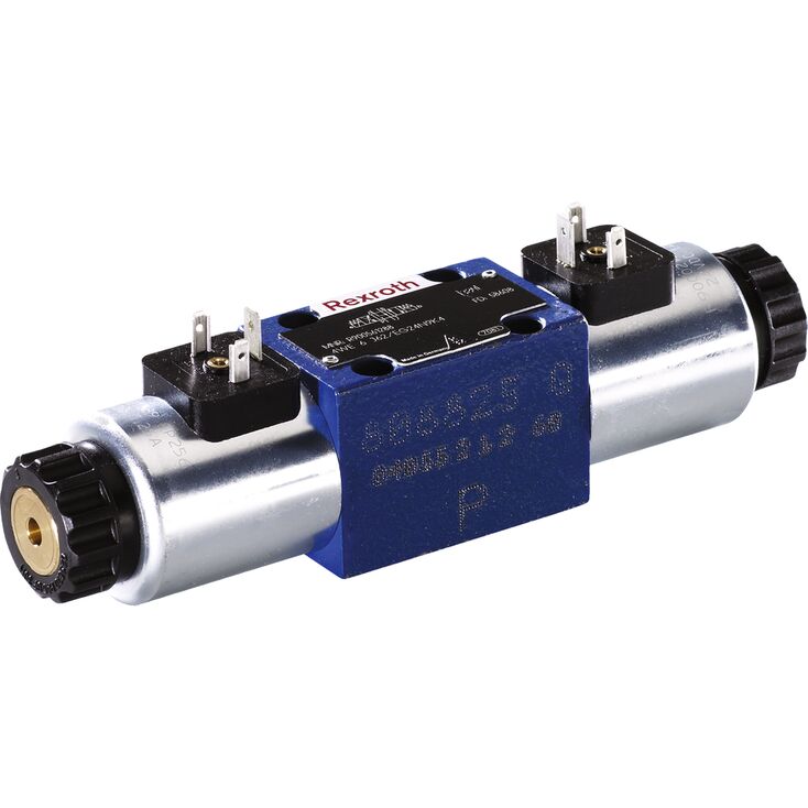
4WE6D6X/OFEG24N9K4
Rexroth
R900567512
三位四通、二位四通或二位三通型式。
油口布置符合ISO 4401-03-02-0-05,可带或不带定位孔。
高功率电磁铁,可选旋转90°的结构。
电气连接可采用独立连接或集中连接。
可选辅助操纵装置。
可选阀芯位置监测。
对于高于50 VAC或75 VDC的电压,符合低电压指令2014/35/EU的CE要求。
电磁线圈可选作为认可部件,带符合1982版UL 906的UR标志。
可选符合CSA C22.2第139-1982号的认证。
WE 型换向阀为电磁铁驱动的滑阀式换向阀,可作为电磁控制元件使用,用于控制油流的通断及方向。
换向阀主要由阀体(1)、一个或两个电磁铁(2)、控制阀芯(3)及复位弹簧(4)组成。
断电状态下,控制阀芯(3)由复位弹簧(4)保持在中位或初始位置,“O”型除外。
油中切换的电磁铁(2)通电后,控制阀芯(3)从静止位置移向所需端位,接通所选符号要求的流向。
电磁铁(2)断电后,控制阀芯(3)被推回中位或初始位置,带“OF”定位机构的阀以及“O”型无弹簧阀除外。
辅助操作装置(5)允许在电磁铁未供电时手动切换阀。
液压系统必须正确排气,以确保正常功能。
“O”:无弹簧复位,仅适用于A、C、D机能。
该版本为带两个切换位置、两个电磁铁但不带定位装置的换向阀。控制阀芯(3)无弹簧复位,断电时没有确定的基本位置。
“OF”:无弹簧复位,带定位装置,仅适用于A、C、D机能。
该版本为带两个切换位置、两个电磁铁及定位装置的换向阀。定位装置将控制阀芯(3)固定在相应切换位置,运行期间无需持续给电磁铁供电,有助于节能。
“.73...A12”版本,具有柔和切换特性。
控制阀芯与电磁铁的组合可显著减小阀通断时的切换冲击。与标准阀相比,按加速度a测得的切换冲击可降低约85%,具体取决于阀芯版本,参见“加速度值”。
注意事项:
两个或多个阀共用泄油管时,管路中的压力峰值可能使带定位机构的阀发生意外阀芯移动。建议分别敷设回油管,或在泄油管中安装单向阀。
由于结构原理所限,阀存在固有的内泄漏,且内泄漏可能在使用寿命内增加。
4WE 6 E6X/...E...型。
节流插芯。
若运行条件导致切换过程中出现超过阀性能极限的流量,则必须使用节流插芯。
01 | 02 | 03 | 04 | 05 | 06 | 07 | 08 | 09 | 10 | 11 | 12 | 13 | 14 | 15 | 16 | 17 | 18 | 19 | 20 | 21 | ||
WE | 6 | 6X | / | E | / | * |
01 | 3 main ports | 3 | ||||||||
4 main ports | 4 | |||||||||
02 | Directional valve | WE | ||||||||
03 | Size 6 | 6 | ||||||||
04 | Symbols; for the possible version, see "Symbols/Circuit diagrams" | |||||||||
05 | Component series 60 … 69 (60 … 69: unchanged installation and connection dimensions) | 6X | ||||||||
06 | With spring return | no code | ||||||||
Without spring return | O | |||||||||
Without spring return with detent | OF | |||||||||
07 | High-power solenoid, wet-pin, with detachable coil | E | ||||||||
Electrical voltages | ||||||||||
08 | For ordering code see "Electrical connections and available voltages" below. | e.g. G24 | ||||||||
Manual override 1) | ||||||||||
09 | Without manual override | no code | ||||||||
With manual override | N 3) | |||||||||
With manual override "mushroom button" (small) | N2 3) | |||||||||
With lockable manual override "mushroom button" (small) | N4 2; 3) | |||||||||
With lockable manual override "mushroom button" (large) | N5 2); 3; 4) | |||||||||
With manual override "mushroom button" (large), not lockable | N6 3; 4) | |||||||||
With lockable manual override "nut" | N72; 3) | |||||||||
With concealed manual override (standard) | N9 | |||||||||
Corrosion resistance (outside) (for the availability, refer to the following table) | ||||||||||
10 | None (valve housing primed) | no code | ||||||||
Improved corrosion protection (240 h salt spray test according to EN ISO 9227) | J3 | |||||||||
High corrosion protection (720 h salt spray test according to EN ISO 9227) | J5 | |||||||||
Electrical connection | ||||||||||
11 | Individual connection or central connection | |||||||||
For ordering code see "Electrical connections and available voltages" below. | e.g. K4 | |||||||||
Spool position monitoring (For more information, see data sheet 24830) | ||||||||||
12 | Without position switch | no code | ||||||||
Inductive position switch type QM (valves with 2 spool positions) | ||||||||||
Monitored spool position "a" | QMAG24 | |||||||||
Monitored spool position "b" | QMBG24 | |||||||||
Monitored rest position | QM0G24 | |||||||||
Inductive position switch type QR (valves with 3 spool positions) | ||||||||||
Monitored rest position | QM0G24 | |||||||||
Monitored spool position "a" and "b" | QRABG24E | |||||||||
Inductive position switch type QS | ||||||||||
Monitored spool position "a" | QSAG24W | |||||||||
Monitored spool position "b" | QSBG24W | |||||||||
Monitored spool position "0" | QS0G24W | |||||||||
Monitored spool position "0" and "a" | QS0AG24W | |||||||||
Monitored spool position "0" and "b" | QS0BG24W | |||||||||
Monitored spool position "a" and "b" | QSABG24W | |||||||||
Switching time increase | ||||||||||
13 | Without switching time increase | no code | ||||||||
With switching time increase (only with direct voltage and only with version "N9" and symbol "73") | A12 | |||||||||
Throttle insert | ||||||||||
14 | Without throttle insert (standard) | no code | ||||||||
With throttle insert (when the admissible valve performance limit is exceeded, refer to "Performance limits"): | ||||||||||
Connection | Throttle Ø in mm | |||||||||
0,6 mm | 0,8 mm | 1,0 mm | 1,2 mm | 1,5 mm | 2,0 mm | 2,5 mm | 3,0 mm | 4,0 mm | ||
P | = B06 | = B08 | = B10 | = B12 | = B15 | = B20 | = B25 | = B30 | = B40 | |
A | = H06 | = H08 | = H10 | = H12 | = H15 | = H20 | = H25 | = H30 | = H40 | |
B | = R06 | = R08 | = R10 | = R12 | = R15 | = R20 | = R25 | = R30 | = R40 | |
A and B | = N06 | = N08 | = N10 | = N12 | = N15 | = N20 | = N25 | = N30 | = N40 | |
T | = X06 | = X08 | = X10 | = X12 | = X15 | = X20 | = X25 | = X30 | = X40 | |
Clamping length | ||||||||||
15 | 42 mm (standard) | no code | ||||||||
22 mm | Z | |||||||||
Control spool play | ||||||||||
16 | Standard (recommended) | no code | ||||||||
Minimum (selection for reduced leakage values; higher oil cleanliness required) | T06 | |||||||||
Increased (selection with high temperature difference hydraulic fluid/environment; leads to higher internal leakage values) | T12 | |||||||||
Seal material (observe compatibility of seals with hydraulic fluid used, see "Technical data") | ||||||||||
17 | NBR seals | no code | ||||||||
FKM seals | V | |||||||||
Recommended for operation with HFC hydraulic fluids together with high temperatures | MH | |||||||||
Low-temperature version (only with version "Without manual override") | MT | |||||||||
18 | Standard | no code | ||||||||
Solenoid coil as approved component with UR marking according to UL 906, edition 1982 5) | = UR | |||||||||
Approval according to CSA C22.2 no. 139-1982 | = CSA | |||||||||
Porting pattern according to ANSI B93.9 6) | = AN | |||||||||
19 | Without locating hole | no code | ||||||||
With locating hole and locking pin ISO 8752-3x8-St | /62 | |||||||||
20 | Standard | no code | ||||||||
With reduced electric power consumption (only versions "G24" as well as "K4", "DL" and "DKL") | SO407 | |||||||||
21 | Further details in the plain text | * | ||||||||
| 1) | Operation of the manual override only possible up to 50 bar [725 psi] tank pressure. Avoid damage to the bore of the manual override. (Special tool for the operation, separate order, material no. R900024943). If the manual override is blocked, operation of the opposite solenoid is to be excluded. The manual override cannot be allocated a safety function. |
| 2) | With tank pressures higher than 50 bar, it is not guaranteed that the valve remains in the position into which it was switched by the lockable manual override ("N4", "N5", "N7"). |
| 3) | Only direct voltage; not for version "= UR" |
| 4) | Only direct voltage; not for version "SO407" |
| 5) | Only for version "K4" with "G12", "G24" and "W110" |
| 6) | With power supply to - solenoid "a", channel P is connected to a - solenoid "b", channel P is connected to B |
Electrical connection | Manual override | ||||||||
"K4" | "DL" | "K40", "C4" | |||||||
"G12" | "G24" | "G24" | "G48" | "G12" | "G24" | "G26" | Ohne | "N" | |
"J3" | ✔ | ✔ | ✔ | ✔ | - | - | - | ✔ | ✔ |
"J5" | - | - | - | - | ✔ | ✔ | ✔ | ✔ | ✔ |
(special voltages upon request)
Connector | Ordering code | Electrical voltages | Protection class according to EN 60529 1) | Protection class according to VDE 0580 | |||||||||
12 V | 24 V | 26 V | 48 V | 96 V | 110 V | 125 V | 205 V | 220 V | |||||
Ordering code | |||||||||||||
G12 | G24 | G26 | G48 | G96 | G110 | G125 | G205 | G220 | |||||
3-pole connector (2+PE) according to DIN EN 175301-803 |
| K4 | ✔ | ✔ | - | ✔ | ✔ | ✔ | ✔ | ✔ | ✔ | IP65 | I 2) |
| K4K | ✔ | ✔ | ✔ | - | - | - | - | - | - | IP65 | I 2) | |
Connector 2-pole, DT04-2PA (Deutsch type) | K40 | ✔ | ✔ | ✔ | - | - | - | - | - | - | IP65 | III 3) | |
Connector, 4-pole, M12x1 according to DIN EN 61076-2-101, with suppressor diode, coding A |
| K72L | - | ✔ | - | - | - | - | - | - | - | IP65 | III 3) |
| K73L | - | ✔ | - | - | - | - | - | - | - | IP65 | III 3) | |
Connector 2-pole (Junior-Timer type) |
| C4 | ✔ | ✔ | ✔ | - | - | - | - | - | - | IP65 | III 3) |
Maximum admissible overvoltages according to DIN EN 60664-1:2008-01 (VDE 0110-1) (overvoltage category II): | |||||||||||||
Nominal voltage UNom | V | 12 | 24 | 26 | 48 | 96 | 110 | 125 | 205 | 220 | |||
Rated current INom | A | 2,5 | 1,25 | 1,17 | 0,66 | 0,33 | 0,25 | 0,17 | 0,16 | 0,14 | |||
Maximum admissible switch-off overvoltage according to VDE 0580 | V | 500 | 500 | 500 | 500 | 500 | 500 | 500 | 500 | 500 | |||
Recommended interference protection circuit with 2 x mains voltage | V | 24 | 48 | 52 | 96 | 192 | 220 | 250 | 410 | 440 | |||
| 1) | Only with correctly mounted valve with a mating connector suitable for the protection class. |
| 2) | Protection class I with properly connected protective grounding conductor (PE) and valve mounting surface connected to the protective grounding conductor system. |
| 3) | With protection class III, a protective extra-low voltage with isolation transformer (PELV, SELV) is to be provided. |
Notice:
Solenoid valves induce voltage peaks during switch-off. In order to prevent electro-magnetic interference at the system and damage to the valve control, an interference protection circuit has to be provided on the system side. Alternatively, you can also select a connector with integrated interference protection circuit.
Connector | Ordering code | Electrical voltages | Protection class according to EN 60529 1) | Protection class according to VDE 0580 | |||||||
12 V | 24 V | 48 V | 96 V | 110 V | 125 V | 220 V | |||||
Ordering code | |||||||||||
G12 | G24 | G48 | G96 | G110 | G125 | G220 | |||||
Cable gland, terminal area 6 … 12 mm | With indicator light | DL | ✔ | ✔ | ✔ | ✔ | ✔ | ✔ | ✔ | IP65 | I 2) |
With indicator light and interference protection circuit | DL1 | ✔ | ✔ | ✔ | ✔ | ✔ | ✔ | ✔ | IP65 | I 2) | |
Cable gland, threaded connection 1/2"-14 NPT | With indicator light | DAL | ✔ | ✔ | - | - | - | ✔ | - | IP65 | I 2) |
With indicator light and interference protection circuit | DAL1 | ✔ | ✔ | - | - | - | ✔ | - | IP65 | I 2) | |
7-pole connector (6+PE) according to DIN EN 175201-804 | With indicator light | DK6L | - | ✔ | ✔ | - | ✔ | ✔ | ✔ | IP65 | I 2) |
With indicator light and interference protection circuit | DK6L1 | - | ✔ | ✔ | - | ✔ | ✔ | ✔ | IP65 | I 2) | |
Connector according to ANSI/B93.55M-1981 (Brad Harrison Mini-Change) | With indicator light, 3-pole | DK23L | - | ✔ | - | - | - | - | - | IP65 | I 2) |
With indicator light, 5-pole | DK25L | - | ✔ | - | - | - | - | - | IP65 | I 2) | |
Connector, 4-pole, M12x1 according to DIN EN 61076-2-101 | With indicator light | DK24L | - | ✔ | - | - | - | - | - | IP65 | III 3) |
With indicator light and interference protection circuit | DK24L1 | - | ✔ | - | - | - | - | - | IP65 | III 3) | |
With indicator light and interference protection circuit | DK35L | - | ✔ | - | - | - | - | - | IP65 | III 3) | |
Maximum admissible overvoltages according to DIN EN 60664-1:2008-01 (VDE 0110-1) (overvoltage category II): | |||||||||||
Nominal voltage UNom | V | 12 | 24 | 48 | 96 | 110 | 125 | 220 | |||
Rated current INom | A | 2,5 | 1,25 | 0,66 | 0,33 | 0,25 | 0,17 | 0,14 | |||
Maximum admissible switch-off overvoltage according to VDE 0580 | V | 500 | 500 | 500 | 500 | 500 | 500 | 500 | |||
Recommended interference protection circuit with 2 x mains voltage | V | 24 | 48 | 96 | 192 | 220 | 250 | 440 | |||
| 1) | Only with correctly mounted valve with a mating connector suitable for the protection class. |
| 2) | Protection class I with properly connected protective grounding conductor (PE) and valve mounting surface connected to the protective grounding conductor system. |
| 3) | With protection class III, a protective extra-low voltage with isolation transformer (PELV, SELV) is to be provided. |
Notice:
Solenoid valves induce voltage peaks during switch-off. In order to prevent electro-magnetic interference at the system and damage to the valve control, an interference protection circuit has to be provided on the system side. Alternatively, you can also select a connector with integrated interference protection circuit.
Connector | Ordering code | Electrical voltages | Protection class according to EN 60529 1) | Protection class according to VDE 0580 | ||||||||||
100 V 50/60 Hz | 100 V 50/60 Hz | 110 V 50/60 Hz | 110 V 50/60 Hz | 120 V 60 Hz | 120 V 60 Hz | 200 V 50 Hz | 200 V 50 Hz | 230 V 50/60 Hz | 230 V 50/60 Hz | |||||
Ordering code | ||||||||||||||
G96 | W110 | G96 | W110 | G110 | W110 | G180 | W200 | G205 | W230 | |||||
3-pole connector (2+PE) according to DIN EN 175301-803 | Standard | K4 | ✔ | ✔ | ✔ | ✔ | ✔ | ✔ | ✔ | ✔ | ✔ | ✔ | IP65 | I 2) |
Rectifier required (see "Accessories") | ✔ | ✔ | ✔ | - | ✔ | - | ✔ | - | ✔ | - | ||||
Maximum admissible overvoltages according to DIN EN 60664-1:2008-01 (VDE 0110-1) (overvoltage category II): | ||||||||||||||
Nominal voltage UNom | V | 100 | 100 | 110 | 110 | 120 | 120 | 200 | 200 | 230 | 230 | |||
Rated current INom |
| A | 0,31 | 0,56 | 0,34 | 0,52 | - | - | 0,18 | 0,29 | 0,16 | 0,23 | ||
| A | 0,31 | 0,44 | 0,34 | 0,39 | 0,30 | 0,45 | - | - | 0,16 | 0,17 | |||
Lower rated current |
| A | - | 0,65 | - | 0,6 | - | - | - | 0,33 | - | 0,27 | ||
| A | - | 0,51 | - | 0,45 | - | 0,52 | - | - | - | 0,2 | |||
Upper rated current |
| A | - | 0,9 | - | 0,9 | - | - | - | 0,6 | - | 0,36 | ||
| A | - | 0,9 | - | 0,6 | - | 0,9 | - | - | - | 0,36 | |||
Maximum admissible switch-off overvoltage according to VDE 0580 | V | 500 | 500 | 500 | 500 | 500 | 500 | 500 | 500 | 500 | 500 | |||
Recommended interference protection circuit with 2 x mains voltage | V | 200 | 200 | 220 | 220 | 240 | 240 | 400 | 400 | 460 | 460 | |||
| 1) | Only with correctly mounted valve with a mating connector suitable for the protection class. |
| 2) | Protection class I with properly connected protective grounding conductor (PE) and valve mounting surface connected to the protective grounding conductor system. |
Notices:
Solenoid valves induce voltage peaks during switch-off. In order to prevent electro-magnetic interference at the system and damage to the valve control, an interference protection circuit has to be provided on the system side. Alternatively, you can also select a connector with integrated interference protection circuit.
Depending on the rated current INom, circuit breakers according to tripping characteristic "K" are to be provided.
The tripping current must lie within a time interval of 0.6 s with 8 to 10 times the nominal power supply.
The required non-tripping current of the fuse must not fall below the "lower rated current" value (see preceding table). The maximum tripping current must not exceed the "upper rated current" value (see preceding table).
The temperature dependence of the tripping behavior of the circuit breakers has to be considered according to the manufacturer's specifications.
Connector | Ordering code | Electrical voltages | Protection class according to EN 60529 1) | Protection class according to VDE 0580 | ||||||||
100?V?50/60?Hz | 110 V 50/60 Hz | 110 V 50/60 Hz | 120 V 60 Hz | 120 V 60 Hz | 200 V 50 Hz | 230 V 50/60 Hz | 230 V 50/60 Hz | |||||
Ordering code | ||||||||||||
W100 | W110R | W110 | W120R | W110 | W200 | W230R | W230 | |||||
Cable gland, terminal area 6 … 12 mm | With indicator light | DL | ✔ | ✔ | ✔ | ✔ | ✔ | ✔ | ✔ | ✔ | IP65 | I 2) |
With indicator light and interference protection circuit | DL1 | ✔ | ✔ | ✔ | ✔ | ✔ | ✔ | ✔ | ✔ | IP65 | I 2) | |
With indicator light and interference protection circuit 3) | DJL | ✔ | - | - | - | - | ✔ | - | - | IP65 | I 2) | |
Cable gland, threaded connection 1/2"-14 NPT | With indicator light | DAL | ✔ | ✔ | ✔ | ✔ | ✔ | - | ✔ | ✔ | IP65 | I 2) |
With indicator light and interference protection circuit | DAL1 | - | ✔ | ✔ | ✔ | ✔ | - | ✔ | ✔ | IP65 | I 2) | |
7-pole connector (6+PE) according to DIN EN 175201-804 | With indicator light | DK6L | - | ✔ | ✔ | ✔ | ✔ | - | - | - | IP65 | I 2) |
With indicator light and interference protection circuit | DK6L1 | - | ✔ | ✔ | ✔ | ✔ | - | - | - | IP65 | I 2) | |
Connector according to ANSI/B93.55M-1981 (Brad Harrison Mini-Change) | With indicator light, 3-pole | DK23L | - | ✔ | ✔ | ✔ | ✔ | - | - | - | IP65 | I 2) |
With indicator light, 5-pole | DK25L | - | ✔ | ✔ | ✔ | ✔ | - | - | - | IP65 | I 2) | |
Maximum admissible overvoltages according to DIN EN 60664-1:2008-01 (VDE 0110-1) (overvoltage category II): | IP65 | I 2) | ||||||||||
Nominal voltage UNom | V | 100 | 110 | 110 | 120 | 120 | 200 | 230 | 230 | |||
Rated current INom |
| A | 0,56 | 0,34 | 0,52 | - | - | 0,29 | 0,16 | 0,23 | ||
| A | 0,44 | 0,34 | 0,39 | 0,30 | 0,45 | - | 0,16 | 0,17 | |||
Lower rated current |
| A | 0,65 | - | 0,6 | - | - | 0,33 | - | 0,27 | ||
| A | 0,51 | - | 0,45 | - | 0,52 | - | - | 0,2 | |||
Upper rated current |
| A | 0,9 | - | 0,9 | - | - | 0,6 | - | 0,36 | ||
| A | 0,9 | - | 0,6 | - | 0,9 | - | - | 0,36 | |||
Maximum admissible switch-off overvoltage according to VDE 0580 | V | 500 | 500 | 500 | 500 | 500 | 500 | 500 | 500 | |||
Recommended interference protection circuit with 2 x mains voltage | V | 200 | 220 | 220 | 220 | 240 | 400 | 460 | 460 | |||
| 1) | Only with correctly mounted valve with a mating connector suitable for the protection class. |
| 2) | Protection class I with properly connected protective grounding conductor (PE) and valve mounting surface connected to the protective grounding conductor system. |
| 3) | Wire bridge between pin 2- and 4-. |
Notices:
Solenoid valves induce voltage peaks during switch-off. In order to prevent electro-magnetic interference at the system and damage to the valve control, an interference protection circuit has to be provided on the system side. Alternatively, you can also select a connector with integrated interference protection circuit.
Depending on the rated current INom, circuit breakers according to tripping characteristic "K" are to be provided.
The tripping current must lie within a time interval of 0.6 s with 8 to 10 times the nominal power supply.
The required non-tripping current of the fuse must not fall below the "lower rated current" value (see preceding table). The maximum tripping current must not exceed the "upper rated current" value (see preceding table).
The temperature dependence of the tripping behavior of the circuit breakers has to be considered according to the manufacturer's specifications.
Size | 6 | ||
Weight | Valve with one solenoid | kg | 1.45 |
Valve with two solenoids | kg | 1.95 | |
Installation position | any | ||
Ambient temperature range | NBR seals | °C | -20 … +50 |
FKM seals | °C | -15 … +50 | |
Version for HFC hydraulic fluid | °C | -20 … +50 | |
Low-temperature version 1) | °C | -40 … +50 | |
Storage temperature range | °C | +5 … +40 | |
MTTFD values according to EN ISO 13849 2) | Years | 300 | |
| 1) | For the use at low temperatures, see Project planning information |
| 2) | For further details, see data sheet 08012 |
Size | 6 | |||
Maximum operating pressure | Port P | Standard version | bar | 350 |
Version "SO407" | bar | 315 | ||
Port A | Standard version | bar | 350 | |
Version "SO407" | bar | 315 | ||
Port B | Standard version | bar | 350 | |
Version "SO407" | bar | 315 | ||
Port T | Direct voltage 1) | bar | 210 | |
AC voltage 1) | bar | 160 | ||
Maximum flow | Direct voltage | Standard version | l/min | 80 |
Version "SO407" | l/min | 60 | ||
AC voltage | l/min | 60 | ||
Flow cross-section (spool position 0) | Symbol Q | approx. 6 % of nominal cross-section | ||
Symbol W | approx. 3 % of nominal cross-section | |||
Hydraulic fluid | see table "Hydraulic fluid" | |||
Hydraulic fluid temperature range | NBR seals | °C | -20 … +80 | |
FKM seals | °C | -15 … +80 | ||
Version for HFC hydraulic fluid | °C | -20 … +50 | ||
Low-temperature version 2) | °C | -40 … +50 | ||
Viscosity range | mm²/s | 2.8 … 500 | ||
Maximum admissible degree of contamination of the hydraulic fluid, cleanliness class according to ISO 4406 (c) 3) | Class 20/18/15 | |||
| 1) | With symbols A and B, port T must be used as leakage oil connection if the operating pressure exceeds the admissible tank pressure. |
| 2) | For the use at low temperatures, see Project planning information |
| 3) | The cleanliness classes specified for the components must be adhered to in hydraulic systems. Effective filtration prevents faults and simultaneously increases the life cycle of the components. For the selection of the filters, see www.boschrexroth.com/filter. |
Hydraulic fluid | Classification | Suitable sealing materials | Standards | Data sheet | |
Mineral oils | HL, HLP, HLPD, HVLP, HVLPD | NBR, FKM | DIN 51524 | 90220 | |
Bio-degradable | Insoluble in water | HETG | FKM | ISO 15380 | 90221 |
HEES | FKM | ||||
Soluble in water | HEPG | FKM | ISO 15380 | ||
Flame-resistant | Water-free | HFDU (glycol base) | FKM | ISO 12922 | 90222 |
HFDU (ester base) | FKM | ||||
HFDR | FKM | ||||
Containing water | HFC (Fuchs: Hydrotherm 46M, Renosafe 500; | NBR | ISO 12922 | 90223 | |
Important information on hydraulic fluids:
| |||||
Voltage type | Direct voltage | AC voltage 50/60 Hz | |||
Nominal voltage according to VDE 0580 | See "Type codes" | ||||
Voltage tolerance (nominal voltage) | % | ± 10 | |||
Nominal power according to VDE 0580 | Standard version | W | 30 | - | |
Version "SO407" | W | 8 | - | ||
Version "= UR" | W | 34 | - | ||
Holding power | VA | - | 50 | ||
Switch-on power | VA | - | 220 | ||
Duty cycle | 100% (S1 according to VDE 0580) | ||||
Switching time according to ISO 6403 1) | ON | ms | 25 … 45 | 10 … 20 | |
OFF | ms | 10 … 25 | 15 … 40 | ||
Maximum switching frequency | Standard version | 1/s | 4.2 | 2 | |
Version "SO407" | 1/s | 2 | - | ||
Maximum surface temperature of the coil 2) | Standard version | °C | 120 | 180 | |
Version "SO407" | °C | 85 | - | ||
Version "= UR" | °C | 120 | - | ||
Insulation class VDE 0580 | Standard | F | H | ||
Version "= UR" | Version "G12", "G24" | F | |||
Version "G110", "W120R" | H | ||||
Protection class according to EN 60529 | See "Type codes" | ||||
Protection class according to VDE 0580 | See "Type codes" | ||||
Electrical fuse protection | Maximum admissible switch-off overvoltage see "Type codes". Every solenoid must be protected individually, using a suitable fuse with tripping characteristics K (inductive loads). | ||||
Protective earthing conductor and screening | The valve must be installed on a surface that is included in the equipotential bonding. Connector pin assignment (CE-compliant installation) see "Electrical connection". | ||||
Conformity | CE according to Low-Voltage Directive 2014/35/EU checked according to EN 60204-1:2006-01 and DIN VDE 0580, classified as component. | ||||
| 1) | Measured without flow. The switching times were determined for a hydraulic fluid temperature of 40 °C and a viscosity of 46 mm2/s. Switching times change dependent on hydraulic fluid temperatures, operating time and application conditions. |
| 2) | Due to the temperatures occurring at the surfaces of the solenoid coils, the standards ISO 13732-1 and ISO 4413 need to be adhered to!The specified surface temperature in AC solenoids is valid for fault-free operation. In the error case (e.g. blocking of the control spool), the surface temperature may increase above 180 °C. Thus, the system must be checked for possible dangers considering the ignition temperature of the hydraulic fluid used. As fuse protection, circuit breakers must be used, unless the creation of an ignitable atmosphere can be excluded in a different way. In this way, the surface temperature in an error case can be limited to a maximum of 220 °C. You have to use cables that have been approved of for a working temperature of more than 50 °C (individual connection) and/or 90 °C (central connection). |
注意事项:
不得对电磁线圈涂漆。
必须防止同一阀的 2 个电磁铁同时通电。
快速接通:为加快电磁铁侧的接通速度,采用独立连接、额定电压为 12 V 或 24 V 的阀,可在最长 100 ms 内以两倍电压驱动(脉宽调制见数据表 30362)。采用这种方式时,最大允许切换频率降至 3 1/s。
缓冲切换:对于 "A12" 型阀,可对接通和断开过程进行阻尼缓冲,实现平缓切换,从而显著减小系统切换冲击。
Dimensions in mm
| Required surface quality of the valve contact surface |
1 | Solenoid “a” |
2 | Solenoid “b” |
10 | Mating connector without circuitry for connector "K4", separate order, see "Accessories" |
11 | Mating connector (AMP Junior Timer) with connector "C4”, separate order, see "Accessories" |
12 | Mating connector DT 4-2PA (Deutsch plug) with connector "K40", separate order, see "Accessories" |
13 | Mating connector angled with M12x1 plug-in connection and status LED for connector "K72L", separate order, see "Accessories" |
14 | Mating connector with circuitry for “K4” connector, separate order, see "Accessories" |
18 | Name plate |
19 | Identical seal rings for ports A, B, P, T |
20 | Plug screw for valves with one solenoid on B side |
21 | Plug screw for valves with one solenoid on A side |
22 | Space required to remove the mating connector/angled socket |
23 | Space required to remove the coil; dimensions () version "= UR" |
24 | Mounting nut, tightening torque MA = 4+1 Nm |
25 | Porting pattern according toISO 4401-03-02-0-05 (with locating hole for locking pin ISO 8752-3x8-St, material no. R900005694, separate order) |
26 | Alternative clamping length (): 22 mm |
Dimensions in mm
| Required surface quality of the valve contact surface |
1 | Solenoid “a” |
2 | Solenoid “b” |
15 | Cable gland "DL" |
16 | Central plug-in connection "DK6L" |
17 | Mating connectors for valves with central connection and connector "DK6L", separate order, see "Accessories" |
18 | Name plate |
19 | Identical seal rings for ports A, B, P, T |
20 | Plug screw for valves with one solenoid on B side |
21 | Plug screw for valves with one solenoid on A side |
22 | Space required to remove the mating connector/angled socket |
23 | Space required to remove the coil; dimensions () version "= UR" |
24 | Mounting nut, tightening torque MA = 4+1 Nm |
25 | Porting pattern according toISO 4401-03-02-0-05 (with locating hole for locking pin ISO 8752-3x8-St, material no. R900005694, separate order) |
26 | Alternative clamping length (): 22 mm |
27 | Cover |
Dimensions in mm
| Required surface quality of the valve contact surface |
3 | Without manual override |
4 | Concealed manual override "N9" (standard); dimensions () version "= UR" |
5 | Manual override "N" |
6 | Lockable manual override "mushroom button" (small) "N4" |
7 | Lockable manual override "nut" "N7" |
8 | Lockable manual override "mushroom button" (large) "N5" |
9 | Manual override "mushroom button" (large), not lockable "N6" |
Dimensions in mm
| Required surface quality of the valve contact surface |
1 | Solenoid “a” |
2 | Solenoid “b” |
3 | Without manual override |
5 | Manual override "N" |
6 | Lockable manual override "mushroom button" (small) "N4" |
10 | Mating connector without circuitry for connector "K4", separate order, see "Accessories" |
14 | Mating connector with circuitry for “K4” connector, separate order, see "Accessories" |
18 | Name plate |
19 | Identical seal rings for ports A, B, P, T |
20 | Plug screw for valves with one solenoid on B side |
21 | Plug screw for valves with one solenoid on A side |
22 | Space required to remove the mating connector/angled socket |
23 | Space required to remove the coil; dimensions () version "= UR" |
24 | Mounting nut, tightening torque MA = 4+1 Nm |
25 | Porting pattern according toISO 4401-03-02-0-05 (with locating hole for locking pin ISO 8752-3x8-St, material no. R900005694, separate order) |
26 | Alternative clamping length (): 22 mm |
Dimensions in mm
| Required surface quality of the valve contact surface |
1 | Solenoid “a” |
2 | Solenoid “b” |
3 | Without manual override |
5 | Manual override "N" |
6 | Lockable manual override "mushroom button" (small) "N4" |
15 | Cable gland "DL" |
16 | Central plug-in connection "DK6L" |
17 | Mating connectors for valves with central connection and connector "DK6L", separate order, see "Accessories" |
18 | Name plate |
19 | Identical seal rings for ports A, B, P, T |
20 | Plug screw for valves with one solenoid on B side |
21 | Plug screw for valves with one solenoid on A side |
22 | Space required to remove the mating connector/angled socket |
23 | Space required to remove the coil; dimensions () version "= UR" |
24 | Mounting nut, tightening torque MA = 4+1 Nm |
25 | Porting pattern according toISO 4401-03-02-0-05 (with locating hole for locking pin ISO 8752-3x8-St, material no. R900005694, separate order) |
26 | Alternative clamping length (): 22 mm |
27 | Cover |
Clamping length | Quantity | Hexagon socket head cap screws | Material number |
42 mm | 4 | ISO 4762 - M5 x? 50 - 10.9-flZn-240h-L (Friction coefficient μtotal = 0.09 … 0.14) Tightening torque MA = 7 Nm ±10 % | R913043758 |
or | |||
4 | ISO 4762 - M5 x 50? - 10.9 (Friction coefficient μtotal = 0,12 … 0,17) Tightening torque MA = 8,1 Nm ±10 % | Not included in the Rexroth delivery range | |
or | |||
4 | UNC 10-24 UNC x 2" ASTM-A574 (Friction coefficient μtotal = 0,19 … 0,24) Tightening torque MA = 11 Nm ±15 % | R978800693 | |
UNC 10-24 UNC x 2" ASTM-A574 (Friction coefficient μtotal = 0,12 … 0,17) Tightening torque MA = 8 Nm ±10 % | |||
22 mm | 4 | ISO 4762 - M5 x 30 - 10.9-flZn-240h-L (Friction coefficient μtotal = 0.09 … 0.14) Tightening torque MA = 7 Nm ±10 % | R913048086 |
or | |||
4 | ISO 4762 - M5 x 30 - 10.9 (Friction coefficient μtotal = 0,12 … 0,17) Tightening torque MA = 8,1 Nm ±10 % | Not included in the Rexroth delivery range | |
or | |||
4 | UNC 10-24 UNC x 2" ASTM-A574 (Friction coefficient μtotal = 0,19 … 0,24) Tightening torque MA = 11 Nm ±15 % | R978802879 | |
UNC 10-24 UNC x 2" ASTM-A574 (Friction coefficient μtotal = 0,12 … 0,17) Tightening torque MA = 8 Nm ±10 % | |||