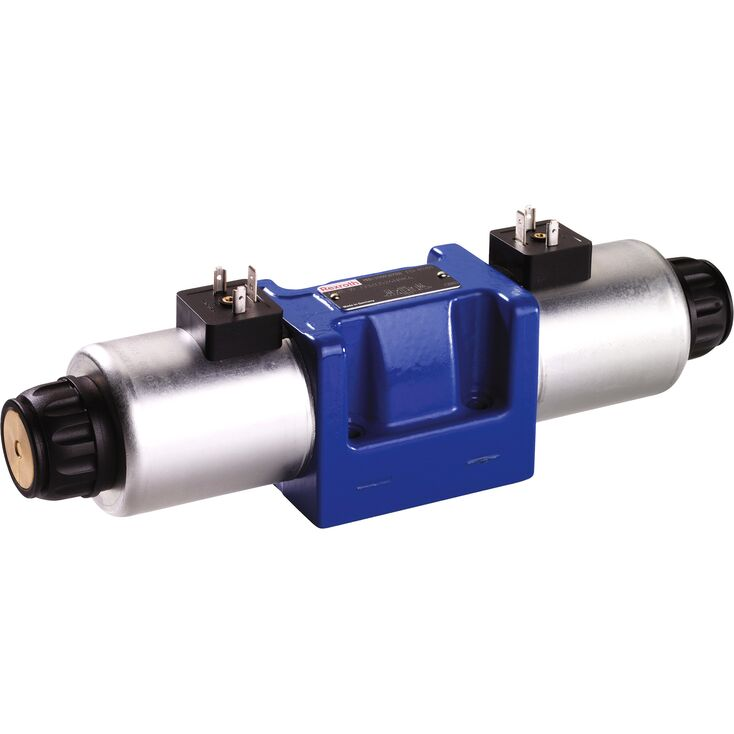
4WE 10 E5X/HG24N9K4/M
Rexroth
R901390857
三位四通、二位四通或二位三通型式。
油口布置符合ISO 4401-05-04-0-05。
高功率电磁铁,可选旋转90°的结构。
电气连接可采用独立连接或集中连接。
可选用PWM连接器,以实现快速开关放大及降低能耗。
可选辅助操纵装置。
对于高于50 VAC或75 VDC的电压,符合低电压指令2006/95/EC的CE要求。
电磁线圈获得UL 429的UR认可。
可选符合CSA C22.2第139-10号的认证。
WE型换向阀是电磁驱动的滑阀换向阀,可用作电磁元件,控制液流的启动、停止及方向。
换向阀主要由阀体(1)、一个或两个电磁铁(2)、控制阀芯(3)及复位弹簧(4)组成。
断电状态下,控制阀芯(3)由复位弹簧(4)保持在中位或初始位置,“O”型除外。
湿式电磁铁(2)通电后,控制阀芯(3)从静止位置移至所需终端位置,从而按所选机能符号接通相应的流动方向。
电磁铁(2)断电后,控制阀芯(3)被推回中位或初始位置,带“OF”定位机构的阀以及“O”型无弹簧阀除外。
手动应急操作装置(6)允许在电磁铁未通电时手动切换阀。
为确保正常功能,必须使电磁铁的耐压腔充满油液。
更多功能请参阅功能说明。
“B..”节流插芯。
在P、A、B或T通道中使用节流插芯(7),可增大阀的流动阻力。运行条件导致切换过程中出现超过阀性能极限的流量时,必须采用该插芯。
“O”:无弹簧复位,仅适用于A、C、D机能。
该版本为带两个阀位、两个电磁铁但不带定位装置的换向阀。控制阀芯(3)无弹簧复位,因此断电时没有确定的基本位置。
“OF”:无弹簧复位,带定位装置,仅适用于A、C、D机能。
该版本为带两个阀位、两个电磁铁及定位装置的换向阀。定位装置将控制阀芯(3)锁定在相应阀位,因此运行期间无需持续向电磁铁供电,有助于节能。
注意!
两个或多个阀共用油箱回油管时,管路中的压力峰值可能使带定位机构的阀发生意外阀芯移动!因此,建议分别敷设回油管,或在回油管中安装单向阀。
01 | 02 | 03 | 04 | 05 | 06 | 07 | 08 | 09 | 10 | 11 | 12 | 13 | 14 | 15 | 16 | 17 | ||
WE | 10 | 5X | / | E | / | * |
01 | 3 main ports | 3 | ||
4 main ports | 4 | |||
02 | Directional valve | WE | ||
03 | Size 10 | 10 | ||
04 | Symbols e. g. C, E, EA, EB, etc.; for the possible version, see Symbols | z. B. C | ||
05 | Component series 50 … 59 (50 … 59: unchanged installation and connection dimensions) | 5X | ||
06 | With spring return | no code | ||
With reinforced compression spring | D | |||
Without spring return | O | |||
Without spring return with detent | OF | |||
07 | High-power solenoid, wet-pin, with detachable coil | E | ||
08 | Direct voltage 12 V | G12 | ||
Direct voltage 24 V | G24 | |||
Direct voltage 26 V | G26 | |||
Direct voltage 48 V | G48 | |||
Nominal voltage 96 V at DC solenoid in operation with AC voltage mains (AC voltage mains 100/110 V - 50/60 Hz with an admissible voltage tolerance of +/- 10 %) | G96 | |||
Direct voltage 110 V | G1101) | |||
Direct voltage 125 V | G125 | |||
Nominal voltage 180 V at DC solenoid in operation with AC voltage (AC voltage mains 200 V - 50/60 Hz with an admissible voltage tolerance of +/- 10 %) | G180 | |||
Nominal voltage 205 V at DC solenoid with operation with AC voltage mains (AC voltage mains 230 V – 50/60 Hz with an admissible voltage tolerance of +/- 10 %) | G205 | |||
Direct voltage 220 V | G220 | |||
Alternating voltage 100 V | W100R1) | |||
Alternating voltage 110 V | W110R1) | |||
Alternating voltage 120 V | W120R1) | |||
Alternating voltage 200 V | W200R1) | |||
Alternating voltage 230 V | W230R1) | |||
Connection to AC voltage mains via control with rectifier (see table Mating connectors) 2) | ||||
Electrical connections and available voltages see Technical data | ||||
09 | Without manual override | no code | ||
With concealed manual override (standard) | N93) | |||
With concealed manual override and protective cap 5) | N83) | |||
With lockable manual override "mushroom button" (large) | N53; 4) | |||
With manual override "mushroom button" (large), not lockable | N63) | |||
Corrosion resistance (outside) | ||||
10 | None (valve housing primed) | no code | ||
Improved corrosion protection (240 h salt spray test according to EN ISO 9227) (see also Technical data) | J3 | |||
Electrical connection | ||||
11 | Individual connection | |||
Without mating connector; connector DIN EN 175301-803 | K46) | |||
Without mating connector; connector DIN EN 175301-803 (coil with potted-in connector base and sealing element to valve housing (IP67)) | K4K6) 7) | |||
Without mating connector, 4-pole with connector M12 x 1 according to IEC 60947-5-2, integrated interference protection circuit and status LED | K72L 6) | |||
Without mating connector; connector AMP Junior-Timer | C4Z6) | |||
Central connection | ||||
Cable entry at the cover, with indicator light | DL | |||
Central plug-in connection at the cover, with indicator light (without mating connector); connector according to DIN EN 175201-804 | DK6L | |||
Without mating connector; threaded connection 1/2“-14 NPT | DAL | |||
Cable gland at the cover, with indicator light and cable bridge at the ground connection | DJL | |||
Mini-charge connector, 5-pole | DK25L | |||
For further electrical connections and available voltages, see Technical data | ||||
Switching time increase | ||||
12 | Without switching time increase | no code | ||
With switching time increase (only with symbol ".73"; not for version "D" with reinforced compression spring; more information upon request) | A12 | |||
13 | Without throttle insert | no code | ||
With throttle insert 8; 9); | ||||
Connection | Throttle Ø in mm | |||
0,8 mm | 1,0 mm | 1,2 mm | ||
P | B08 | B10 | B12 | |
A | H08 | H10 | H12 | |
B | R08 | R10 | R12 | |
A and B | N08 | N10 | N12 | |
T 10) | X08 | X10 | X12 | |
Further throttle insert diameters upon request. | ||||
Control spool play | ||||
14 | Standard | no code | ||
Minimum (to be selected in case of reduced leakage → higher level of oil cleanliness recommended) | T06 | |||
Increased (to be selected in case of a hydraulic fluid/environment temperature difference >25 K → increased internal leakage) | T12 | |||
Seal material | ||||
15 | NBR seals | M | ||
FKM seals | V | |||
Seals for HFC hydraulic fluids | MH | |||
Low-temperature version | MT | |||
Observe compatibility of seals with hydraulic fluid used. | ||||
16 | Approval according to CSA C22.2 no. 139-10 | CSA | ||
Porting pattern according to ANSI B93.9 (if solenoid "a" is energized, channel P is connected to A) | AN | |||
17 | Further details in the plain text | * | ||
| 1) Only for “central connection” version | |
| 2) Only for “individual connection” version | |
| 3) The manual override cannot be allocated a safety function. The manual override units may only be used up to a tank pressure of 50 bar. | |
| 4) With tank pressures above 50 bar, it cannot be guaranteed that the valve remains in the position switched by the manual override "N5". | |
| 5) Protective cap must be removed prior to actuation. | |
| 6) Mating connectors, separate order, see Mating connectors and data sheet 08006. | |
| 7) Recommended for mobile applications; with additional sealing between solenoid coil and pole tube. | |
| 8) When the admissible valve performance limit is exceeded, throttle inserts are to be installed (see Performance limits). | |
| 9) Not with low-temperature version "MT". | |
| 10) When throttle inserts are used in channel T, the pressure in the working ports and in case of connection to the tank chambers must not exceed 210 bar. |
Notice:
For directional spool valves NG10 with spool position monitoring, see data sheet 23352.
Size | 10 | ||||
Type | Einzelanschluss | Zentralanschluss | |||
Weight | Valve with one solenoid | kg | 3.9 | 4 | |
Valve with two solenoids | kg | 5.5 | 5.6 | ||
Installation position 1) | any | ||||
Ambient temperature range | NBR seals | °C | -20 … +70 | ||
FKM seals | °C | -15 … +70 | |||
HFC hydraulic fluid 2) | °C | -20 … +50 | |||
Low-temperature version | °C | -40 … +50 | |||
Storage temperature range | °C | -20 … +50 | |||
MTTFD values according to EN ISO 13849 3) | Years | 300 | |||
| 1) | With suspended installation, higher sensitivity to contamination. Horizontal installation is recommended. |
| 2) | For the use at low temperatures, see Project planning information |
| 3) | For further details, see data sheet 08012 |
Size | 10 | ||
Maximum operating pressure | Port P | bar | 350 |
Port A | bar | 350 | |
Port B | bar | 350 | |
Port T 1) | bar | 210 | |
Maximum flow | l/min | 160 | |
Flow cross-section (spool position 0) | Symbol Q | approx. 6 % of nominal cross-section | |
Symbol W | approx. 3 % of nominal cross-section | ||
Hydraulic fluid | see table | ||
Hydraulic fluid temperature range 2) | NBR seals | °C | -20 … +80 |
FKM seals | °C | -15 … +80 | |
HFC hydraulic fluid | °C | -20 … +50 | |
Low-temperature version | °C | -40 … +50 | |
Viscosity range | mm²/s | 2.8 … 500 | |
Maximum admissible degree of contamination of the hydraulic fluid 3) | Class 20/18/15 according to ISO 4406 (c) | ||
| 1) | With symbols A and B, port T must be used as leakage oil connection if the operating pressure exceeds the admissible tank pressure. |
| 2) | at the valve working ports of the valve |
| 3) | The cleanliness classes specified for the components must be adhered to in hydraulic systems. Effective filtration prevents faults and simultaneously increases the life cycle of the components. For the selection of the filters, see www.boschrexroth.com/filter. |
Hydraulic fluid | Classification | Suitable sealing materials | Standards | Data sheet | |
Mineral oils | HL, HLP, HLPD, HVLP, HVLPD | NBR, FKM | DIN 51524 | 90220 | |
Bio-degradable | Insoluble in water | HETG | NBR, FKM | ISO 15380 | 90221 |
HEES | FKM | ||||
Soluble in water | HEPG | FKM | ISO 15380 | ||
Containing water | Water-free | HFDU, HFDR | FKM | ISO 12922 | 90222 |
Containing water | HFC (Fuchs Hydrotherm 46M, Petrofer Ultra Safe 620 ) | NBR | ISO 12922 | 90223 | |
Important information on hydraulic fluids:
Flame-resistant – containing water:
Bio-degradable and flame-resistant: When using hydraulic fluids that are simultaneously zinc-solving, zinc may accumulate (700 mg zinc per pole tube). | |||||
Voltage type | Direct voltage | AC voltage | |||
Nominal voltage according to VDE 0580 | V | 12 24 26 48 96 110 125 180 205 220 | 100 1) 110 1) 120 1) 200 1) 230 1) | ||
Voltage tolerance (nominal voltage) | % | ± 10 | |||
Nominal power according to VDE 0580 | W | 40 2) | 40 | ||
Duty cycle | % | 100 3) | |||
Switching time | ON (pressure change 5 %) | ms | 60 … 104 4) | ||
ON (pressure change 95 %) | ms | 90 … 165 4) | |||
OFF (pressure change 5 %) | ms | 12 … 50 5) | 230 … 330 5) | ||
OFF (pressure change 95 %) | ms | 48 … 104 5) | 250 … 360 5) | ||
Switching time according to ISO 6403 | ON | ms | 45 … 60 6) | ||
OFF | ms | 20 … 30 6) | 250 … 360 6) | ||
Maximum switching frequency | 1/h | 15000 | 7200 | ||
Maximum surface temperature of the coil | °C | 140 7) | |||
Insulation class VDE 0580 | F | ||||
Electrical fuse protection | Every solenoid must be protected individually using a suitable fuse with tripping characteristics K (inductive loads). The valve must be installed on a surface that is included in the equipotential bonding. | ||||
Protective earthing conductor and screening | see connector pin assignment (CE-compliant installation) | ||||
Conformity | CE according to Low-Voltage Directive 2006/95/EC tested according to DIN EN 60204-1 (VDE0113-1): 2010-05 and DIN VDE 0580: 2000-07 | ||||
| 1) | Possible with central connection or via rectifier. Mating connectors with rectifier (separate order). Rectifiers must comply with the relevant standards as well as the coil performance data! With a central connection, the rectifier is on the board. |
| 2) | Reduction of the nominal power by approx. 40 % when using a 24 V coil with connector switching amplifier type VT-SSBA1-PWM-1X/V002/5 (separate order, material no. R901265633, see data sheet 30362) |
| 3) | Operating mode according to VDE 0580 |
| 4) | Measured with flow, 80 % performance limit and horizontal installation position. Not with symbols A, B and .73. Reduction of the switching time by approx. 50 % when using a 12 V coil with connector switching amplifier type VT-SSBA1-PWM-1X/V001/5 (separate order, material no. R901265633, see data sheet 30362) |
| 5) | Measured with flow, 80% performance limit and horizontal installation position. |
| 6) | Measured without flow |
| 7) | Surface temperature > 50 °C, provide contact protection. |
注意事项!
不得对电磁线圈涂漆。
仅当油箱压力不超过约 50 bar 时,才能进行手动应急操作。避免损坏手动应急操作装置的孔!应使用专用操作工具(需单独订购,物料号 R900024943)。手动应急操作装置锁定时,必须防止对侧电磁铁通电!
必须防止同一阀的 2 个电磁铁同时通电!
使用获准用于高于 105 °C 工作温度的电缆。
采用独立连接、供电电压为 12 V 或 24 V 的阀,可用两倍电压运行以缩短切换时间。为此,必须在 100 ms 后通过脉宽调制将电压降至阀的额定电压。最大允许切换频率为 3 1 /s。
由于电路板可能过载,采用集中连接的阀不得以两倍电压运行。
若无法满足 VDE 0580 规定的标准环境条件,必须对阀采取专门保护措施!
Electrical connections and available voltages | ||||||||||||||||||
Ordering code connector | Ordering code | Protection class according to DIN EN 60529 1) | Protection class according to VDE 0580 | |||||||||||||||
Direct voltage | AC voltage | |||||||||||||||||
G12 | G24 | G26 | G48 | G96 | G110 | G180 | G205 | G220 | W100R | W110R | W120R | W200R | W230R | |||||
Individual connection | Without mating connector, individual connection with connector according to DIN EN 175301-803 | K4 | ✔ | ✔ | – | ✔ | ✔ | – | ✔ | ✔ | ✔ 3) | – | – | – | – | – | IP65 | | |
K4K2) | ✔ 3) | ✔ 3) | ✔ 3) | – | – | – | – | – | – | – | – | – | – | – | IP65, IP67 | | | ||
Without mating connector, 4-pole with connector M12 x 1 according to IEC 60947-5-2, integrated interference protection circuit and status LED | K72L | – | ✔ 3) | – | – | – | – | – | – | – | – | – | – | – | – | IP65 | ||| 5) | |
Without mating connector; connector AMP Junior-Timer | C4Z | – | – | ✔ 3) | – | – | – | ✔ | – | – | – | – | – | – | – | IP66 | ||| 5) | |
Central connection | Without mating connector; threaded connection 1/2“-14 NPT | DAL | ✔ | ✔ | – | – | ✔ | – | – | ✔ | ✔ | ✔ | ✔ | ✔ | ✔ | ✔ | IP65 6) | | |
Central plug-in connection at the cover, with indicator light (without mating connector); connector according to DIN EN 175201-804 | DK6L7) | ✔ | ✔ | – | – | ✔ | ✔ | – | ✔ | ✔ | ✔ | ✔ | ✔ | ✔ | ✔ | IP65 | | | |
Cable gland at the cover, with indicator light (terminal area 6 … 12 mm) | DL4) | ✔ | ✔ | – | – | ✔ | ✔ | – | ✔ | ✔ | ✔ | ✔ | ✔ | ✔ | ✔ | IP65 | | | |
Cable gland at the cover, with indicator light and cable bridge at the ground connection | DJL4) | – | ✔ | – | – | – | ✔ | – | – | – | ✔ | ✔ | – | ✔ | ✔ | IP65 | | | |
Mini-change connector, 5-pole according to ANSI/B93.55M-1981 | DK25L7) | – | ✔ | – | – | ✔ | – | – | – | – | ✔ | ✔ | ✔ | ✔ | ✔ | IP65 | | | |
| 1) | Only with correctly mounted valve with a mating connector suitable for the protection class. |
| 2) | Recommended for mobile applications; with additional sealing between solenoid coil and pole tube. |
| 3) | Solenoid coils without "Recognized component" according to UL 429 |
| 4) | Possible with version “J3”. |
| 5) | With protection class III, a protective extra-low voltage with isolation transformer (PELV, SELV) is to be provided. |
| 6) | Only with professionally designed connection with appropriate sealing to the central connection. |
| 7) | Connector pin assignment see Electrical connections. |
电气连接时,应按规定连接保护接地导线(PE,接地)。
注意事项:
所使用的插接连接器,不适合在正常带载运行时插入或断开。
阀只能配合适用且已锁紧的配套连接器运行。
Symbol | Direction of flow | |||
P –A | P – B | A – T | B – T | |
A; B | 6 | 6 | – | – |
A73, B73 | 23 | 23 | – | – |
C | 1 | 2 | 5 | 7 |
D | 2 | 2 | 5 | 7 |
D73 | 25 | 26 | 26 | 27 |
E | 17 | 16 | 19 | 21 |
E67 | 4 | 4 | 11 | 24 |
E73 | 17 | 18 | 21 | 21 |
F | 2 | 3 | 22 | 23 |
G | 4 | 4 | 24 | 24 |
G73 | 18 | 18 | 24 | 24 |
H | 14 | 14 | 20 | 21 |
H73 | 14 | 14 | 6 | 9 |
J | 3 | 3 | 9 | 11 |
J73 | 22 | 21 | 23 | 24 |
L | 3 | 3 | 9 | 9 |
L73 | 22 | 10 | 11 | 24 |
M | 14 | 14 | 6 | 8 |
P | 17 | 14 | 20 | 23 |
Q | 16 | 17 | 4 | 8 |
R | 18 | 21 | 18 | 24 |
R73 | 24 | 24 | 23 | 24 |
T | 18 | 4 | 10 | 24 |
U | 3 | 3 | 6 | 11 |
U10 | upon request | |||
U73 | 22 | 22 | 23 | 24 |
V | 17 | 17 | 18 | 20 |
W | upon request | |||
X7 | upon request | |||
X34 | upon request | |||
Y | 17 | 16 | 18 | 21 |
Y11 | 3 | 2 | 4 | 9 |
Y73 | 26 | 26 | 26 | 28 |
Central position: | |||||
Symbol | Direction of flow | ||||
P – A | P – B | B – T | A – T | P – T | |
H | 12 | 12 | 13 | 13 | 15 |
(使用 HLP46 测量,ϑOil = 40 ±5 °C)
注意:
规定的性能极限适用于同时具有两个流动方向的使用情况,例如从 P 到 A,同时从 B 到 T 回流。
由于阀内液动力的作用,在仅有一个流动方向时,例如从 P 到 A 而油口 B 被封闭,允许的性能极限可能显著降低!
此类使用情况,请向我们咨询!
性能极限是在电磁铁达到工作温度、欠压 10 %、且油箱无预加压力的条件下测定的。
Characteristic curve | Symbol |
1 | L |
2 | A |
3 | B |
4 | Y |
5 | E73, Q |
6 | F |
7 | G73 |
8 | M; V |
9 | P |
10 | A73 |
11 | H73 |
Characteristic curve | Symbol |
1 | L |
12 | A/O |
13 | J |
14 | H |
15 | D73 |
16 | B73 |
17 | Y11 |
18 | C; D; E73 |
19 | E67 |
20 | G |
(使用 HLP46 测量,ϑOil = 40 ±5 °C)
注意:
规定的性能极限适用于同时具有两个流动方向的使用情况,例如从 P 到 A,同时从 B 到 T 回流。
由于阀内液动力的作用,在仅有一个流动方向时,例如从 P 到 A 而油口 B 被封闭,允许的性能极限可能显著降低!
此类使用情况,请向我们咨询!
性能极限是在电磁铁达到工作温度、欠压 10 %、且油箱无预加压力的条件下测定的。
Characteristic curve | Symbol |
21 | A; B |
22 | G73 |
23 | F; L73 |
24 | E |
25 | C/O; D/O |
26 | J73 |
27 | U |
Characteristic curve | Symbol |
28 | Q |
29 | V |
30 | P |
31 | R |
32 | R73 |
33 | T |
34 | U73 |
35 | Y73 |