| Availability: | |
|---|---|
| Quantity: | |

M-3SEW6U3X/420MG24N9K4
Rexroth
R900566283
2/2-, 3/2- or 4/2-way version
Porting pattern according to DIN 24340 form A
Porting pattern according to ISO 4401-03-02-0-05
Air-gap DC solenoids with detachable coil
Solenoid coil is rotatable by 90°
The coil can be changed without having to open the pressure-tight chamber
Electrical connection as individual connection
Optional auxiliary operating device
Inductive position switch and proximity sensors (contactless)
General
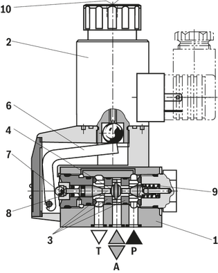
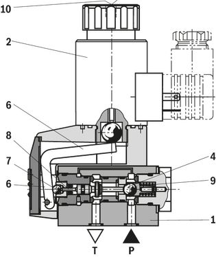
The SEW type directional valve is a directional seat valve with solenoid actuation. It controls the start, stop and direction of flow.
The valve basically consists of the housing (1), the solenoid (2), the hardened valve system (3) as well as the ball/the spool (4) as closing element.
Basic principle
In the initial position, the ball/the spool (4) is pressed onto the seat by the spring (9) and by the solenoid (2) in the switching position. The force of the solenoid (2) acts via the angled lever (6) and the ball (7) on the actuating plunger (8) that is sealed on two sides. The chamber between the two sealing elements is connected to port P. Therefore, the valve system (3) is pressure-compensated in relation to the actuating forces (solenoid or return spring). Therefore, the valves can be used up to 630 bar.
Notices!
3/2-directional seat valves feature "negative spool overlap". Therefore, port T must always be connected. That means that during the switching process – from the starting of the opening of one valve seat to the closing of the other valve seat – ports P–A–T are connected with each other. However, this process takes place within such a short time that it is irrelevant in nearly all cases of use.
The manual override (10) allows for the switching of the valve without solenoid energization.
It is to be ensured that the maximum flow indicated is not exceeded!If applicable, a throttle insert for flow limitation is to be inserted (see functional description).
Type M-3SEW 6 U …
Type M-2SEW 6 N …
With a sandwich plate, the Plus-1 plate, under the 3/2 directional seat valve, the function of a 4/2 directional seat valve is achieved.
Function of the Plus-1 plate
Initial position:
The main valve is not operated. The spring (9) holds the ball (4.1) on the seat (11). Port P is blocked and A is connected to T. Apart from that, one control line is connected from A to the large area of the control spool (12), which is thus unloaded to the tank. The pressure applied via P now pushes the ball (13) onto the seat (14). Now, P is connected to B, and A to T.
Transition position:
When the main valve is actuated, the spool (4.2) is shifted against the spring (9) and pressed onto the seat (15). During this, port T is blocked, while P, A, and B are briefly connected to each other.
Switching position:
P is connected to A. As the pump pressure acts via A on the large area of the control spool (12), the ball (13) is pressed onto the seat (16). Thus, B is connected to T, and P to A. The ball (13) in the Plus-1 plate has a "positive spool overlap".
Notices!
If the annulus area of differential cylinders is not connected to port A, a pressure peak is created in port B during the switching process due to the pressure intensification. This pressure peak may exceed the maximum operating pressure over the permissible limit.
Type M-4SEW 6 Y …

The use of a throttle insert is required when due to prevailing operating conditions, flows can occur during the switching processes, which exceed the performance limit of the valve.
Examples:
Accumulator operation,
use as pilot control valve with internal pilot fluid tapping.
2/2- and 3/2 directional seat valve
The throttle insert is inserted into port P of the seat valve
.
4/2 directional seat valve (see functional description)
The throttle insert is inserted into port P of the Plus-1 plate.
The check valve insert allows a free flow from P to A and closes A to P in a leak-free form.
2/2- and 3/2 directional seat valve (see functional description)
The check valve insert is inserted into port P of the seat valve.
4/2 directional seat valve (see functional description)
The check valve insert is inserted into port P of the Plus-1 plate.
General
The SEW type directional valve is a directional seat valve with solenoid actuation. It controls the start, stop and direction of flow.
The valve basically consists of the housing (1), the solenoid (2), the hardened valve system (3) as well as the ball/the spool (4) as closing element.
Basic principle
In the initial position, the ball/the spool (4) is pressed onto the seat by the spring (9) and by the solenoid (2) in the switching position. The force of the solenoid (2) acts via the angled lever (6) and the ball (7) on the actuating plunger (8) that is sealed on two sides. The chamber between the two sealing elements is connected to port P. Therefore, the valve system (3) is pressure-compensated in relation to the actuating forces (solenoid or return spring). Therefore, the valves can be used up to 630 bar.
Notices!
3/2-directional seat valves feature "negative spool overlap". Therefore, port T must always be connected. That means that during the switching process – from the starting of the opening of one valve seat to the closing of the other valve seat – ports P–A–T are connected with each other. However, this process takes place within such a short time that it is irrelevant in nearly all cases of use.
The manual override (10) allows for the switching of the valve without solenoid energization.
It is to be ensured that the maximum flow indicated is not exceeded!If applicable, a throttle insert for flow limitation is to be inserted (see functional description).
Type M-3SEW 6 U …
Type M-2SEW 6 N …
With a sandwich plate, the Plus-1 plate, under the 3/2 directional seat valve, the function of a 4/2 directional seat valve is achieved.
Function of the Plus-1 plate
Initial position:
The main valve is not operated. The spring (9) holds the ball (4.1) on the seat (11). Port P is blocked and A is connected to T. Apart from that, one control line is connected from A to the large area of the control spool (12), which is thus unloaded to the tank. The pressure applied via P now pushes the ball (13) onto the seat (14). Now, P is connected to B, and A to T.
Transition position:
When the main valve is actuated, the spool (4.2) is shifted against the spring (9) and pressed onto the seat (15). During this, port T is blocked, while P, A, and B are briefly connected to each other.
Switching position:
P is connected to A. As the pump pressure acts via A on the large area of the control spool (12), the ball (13) is pressed onto the seat (16). Thus, B is connected to T, and P to A. The ball (13) in the Plus-1 plate has a "positive spool overlap".
Notices!
If the annulus area of differential cylinders is not connected to port A, a pressure peak is created in port B during the switching process due to the pressure intensification. This pressure peak may exceed the maximum operating pressure over the permissible limit.
Type M-4SEW 6 Y …
The use of a throttle insert is required when due to prevailing operating conditions, flows can occur during the switching processes, which exceed the performance limit of the valve.
Examples:
Accumulator operation,
use as pilot control valve with internal pilot fluid tapping.
2/2- and 3/2 directional seat valve
The throttle insert is inserted into port P of the seat valve
.
4/2 directional seat valve (see functional description)
The throttle insert is inserted into port P of the Plus-1 plate.
The check valve insert allows a free flow from P to A and closes A to P in a leak-free form.
2/2- and 3/2 directional seat valve (see functional description)
The check valve insert is inserted into port P of the seat valve.
4/2 directional seat valve (see functional description)
The check valve insert is inserted into port P of the Plus-1 plate.
01 | 02 | 03 | 04 | 05 | 06 | 07 | 08 | 09 | 10 | 11 | 12 | 13 | 14 | 15 | 16 | ||
M | – | SEW | 6 | 3X | / | M | K4 | / | * |
01 | Mineral oil | M | |||
02 | 2 main ports | 2 | |||
3 main ports | 3 | ||||
4 main ports | 4 | ||||
03 | Seat valve, direct operated | SEW | |||
04 | Size 6 | 6 | |||
05 | Symbols | Main ports | ● = available | ||
2 | 3 | 4 | |||
 | ● | – | – | P | |
 | ● | – | – | N | |
 | – | ● | – | U | |
 | – | ● | – | C | |
 | – | – | ● | D | |
 | – | – | ● | Y | |
06 | Component series 30 ... 39 (30 ... 39: unchanged installation and connection dimensions) | 3X | |||
07 | Operating pressure 420 bar | 420 bar | |||
Operating pressure 630 bar | 630 bar | ||||
08 | High-power solenoid (air-gap) with detachable coil | M | |||
09 | Nominal voltage 96 V at DC solenoid with operation with AC voltage mains (AC voltage mains 110 V/120 V - 50/60 Hz with an admissible voltage tolerance of +/- 10 %) | G96 | |||
Nominal voltage 110 V at DC solenoid with operation with AC voltage mains (AC voltage mains 110 V/120 V – 50/60 Hz with an admissible voltage tolerance of +/-10 %) | G110 | ||||
Nominal voltage 205 V at DC solenoid with operation with AC voltage mains (AC voltage mains 230 V - 50/60 Hz with an admissible voltage tolerance of +/- 10 %) | G205 | ||||
Connection to the AC voltage mains via control with rectifier. Further ordering codes for other voltages are provided in the Technical data | |||||
10 | With concealed manual override (standard) | N9 | |||
Without manual override | no code | ||||
Electrical connection | |||||
11 | Individual connection | ||||
Without mating connector; connector DIN EN 175301-803 | K41) | ||||
Spool position monitoring | |||||
12 | Without position switch | no code | |||
Inductive position switch type QM | |||||
Monitored spool position "a" | QMAG24 2) | ||||
Monitored spool position "b" | QMBG25 2) | ||||
13 | Without check valve insert, without throttle insert | no code | |||
With check valve insert | P | ||||
Throttle Ø 1.2 mm | B12 | ||||
Throttle Ø 1.5 mm | B15 | ||||
Throttle Ø 1.8 mm | B18 | ||||
Throttle Ø 2.0 mm | B20 | ||||
Throttle Ø 2.2 mm | B22 | ||||
Other orifices on request | |||||
Seal material | |||||
14 | NBR seals | no code | |||
FKM seals | V | ||||
Observe compatibility of seals with hydraulic fluid used. (Other seals upon request) | |||||
15 | Without locating hole | no code | |||
With locating hole and locking pin ISO 8752-3x8-St | /62 | ||||
16 | Further details in the plain text | * | |||
1) Mating connectors, separate order.
2) Version “420” only
Notice!
For other types of actuation (e.g. pneumatic, hydraulic, rotary knob, rotary knob with lock, stylus, touching lever, roller actuation), see data sheet 22340 or contact us!
01 | 02 | 03 | 04 | 05 | 06 | 07 | 08 | 09 | 10 | 11 | 12 | 13 | 14 | 15 | 16 | ||
M | – | SEW | 6 | 3X | / | M | K4 | / | * |
01 | Mineral oil | M | |||
02 | 2 main ports | 2 | |||
3 main ports | 3 | ||||
4 main ports | 4 | ||||
03 | Seat valve, direct operated | SEW | |||
04 | Size 6 | 6 | |||
05 | Symbols | Main ports | ● = available | ||
2 | 3 | 4 | |||
| | ● | – | – | P | |
| | ● | – | – | N | |
| | – | ● | – | U | |
| | – | ● | – | C | |
| | – | – | ● | D | |
| | – | – | ● | Y | |
06 | Component series 30 ... 39 (30 ... 39: unchanged installation and connection dimensions) | 3X | |||
07 | Operating pressure 420 bar | 420 bar | |||
Operating pressure 630 bar | 630 bar | ||||
08 | High-power solenoid (air-gap) with detachable coil | M | |||
09 | Nominal voltage 96 V at DC solenoid with operation with AC voltage mains (AC voltage mains 110 V/120 V - 50/60 Hz with an admissible voltage tolerance of +/- 10 %) | G96 | |||
Nominal voltage 110 V at DC solenoid with operation with AC voltage mains (AC voltage mains 110 V/120 V – 50/60 Hz with an admissible voltage tolerance of +/-10 %) | G110 | ||||
Nominal voltage 205 V at DC solenoid with operation with AC voltage mains (AC voltage mains 230 V - 50/60 Hz with an admissible voltage tolerance of +/- 10 %) | G205 | ||||
Connection to the AC voltage mains via control with rectifier. Further ordering codes for other voltages are provided in the Technical data | |||||
10 | With concealed manual override (standard) | N9 | |||
Without manual override | no code | ||||
Electrical connection | |||||
11 | Individual connection | ||||
Without mating connector; connector DIN EN 175301-803 | K41) | ||||
Spool position monitoring | |||||
12 | Without position switch | no code | |||
Inductive position switch type QM | |||||
Monitored spool position "a" | QMAG24 2) | ||||
Monitored spool position "b" | QMBG25 2) | ||||
13 | Without check valve insert, without throttle insert | no code | |||
With check valve insert | P | ||||
Throttle Ø 1.2 mm | B12 | ||||
Throttle Ø 1.5 mm | B15 | ||||
Throttle Ø 1.8 mm | B18 | ||||
Throttle Ø 2.0 mm | B20 | ||||
Throttle Ø 2.2 mm | B22 | ||||
Other orifices on request | |||||
Seal material | |||||
14 | NBR seals | no code | |||
FKM seals | V | ||||
Observe compatibility of seals with hydraulic fluid used. (Other seals upon request) | |||||
15 | Without locating hole | no code | |||
With locating hole and locking pin ISO 8752-3x8-St | /62 | ||||
16 | Further details in the plain text | * | |||
1) Mating connectors, separate order.
2) Version “420” only
Notice!
For other types of actuation (e.g. pneumatic, hydraulic, rotary knob, rotary knob with lock, stylus, touching lever, roller actuation), see data sheet 22340 or contact us!
Size | 6 | ||
Weight | 2/2 directional seat valve | kg | 1.5 |
3/2 directional seat valve | kg | 1.5 | |
4/2 directional seat valve | kg | 2.3 | |
Installation position | any | ||
Ambient temperature range | NBR seals | °C | -30 … +50 |
FKM seals | °C | -20 … +50 | |
Size | 6 | ||
Maximum operating pressure | Port P | bar | 420 630 |
Port A | bar | 420 630 | |
Port B | bar | 420 630 | |
Maximum flow | l/min | 25 | |
Hydraulic fluid | see table | ||
Hydraulic fluid temperature range | NBR seals | °C | -30 … +80 |
FKM seals | °C | -20 … +80 | |
Viscosity range | mm²/s | 2.8 … 500 | |
Maximum admissible degree of contamination of the hydraulic fluid, cleanliness class according to ISO 4406 (c) 1) | Class 20/18/15 according to ISO 4406 (c) | ||
| 1) | The cleanliness classes specified for the components must be adhered to in hydraulic systems. Effective filtration prevents faults and simultaneously increases the life cycle of the components. For the selection of the filters, see www.boschrexroth.com/filter. |
Hydraulic fluid | Classification | Suitable sealing materials | Standards | |
Mineral oils | HL, HLP, HLPD, HVLP, HVLPD | NBR, FKM | DIN 51524 | |
Bio-degradable | Insoluble in water | HETG | NBR, FKM | VDMA 24568 |
HEES | FKM | |||
Soluble in water | HEPG | FKM | VDMA 24568 | |
Containing water | Water-free | HFDU, HFDR | FKM | ISO 12922 |
Containing water | HFC (Fuchs Hydrotherm 46M, Petrofer Ultra Safe 620) | NBR, HNBR | ISO 12922 | |
Important information on hydraulic fluids!
Flame-resistant – containing water:
| ||||
Voltage type | Direct voltage | AC voltage | ||
Available voltages | V | 12 / 24 / 42 / 96 / 110 / 205 / 220 1) | 110 / 120 / 230 | |
Voltage tolerance (nominal voltage) | % | ± 10 | ||
Power consumption | W | 30 | ||
Duty cycle | % | 100 | ||
Switching time according to ISO 6403 | ON (without rectifier) | ms | 25 … 40 | |
ON (with rectifier) | ms | 30 … 55 | ||
OFF (without rectifier) | ms | 10 … 15 | ||
OFF (with rectifier) | ms | 35 … 55 | ||
Maximum switching frequency | Operating pressure ≤350 bar | 1/h | 15000 | |
Operating pressure >350 bar | 1/h | 3600 | ||
Protection class according to EN 60529 | IP65 (If a suitable and a correctly mounted mating connector are used.) | |||
Maximum surface temperature of the coil 2) | °C | 120 | ||
| 1) | Special voltages available upon request |
| 2) | Surface temperature > 50 °C, provide contact protection. |
In the electrical connection, the protective earthing conductor (PE, grounded) is to be connected in accordance with the stipulations.
Connection voltage (DC voltage) | V | 24 | ||
Voltage tolerance (connection voltage) | +30 %/-15 % | |||
Admissible residual ripple | % | ≤ 10 | ||
Max. load capacity | mA | 400 | ||
Switching outputs 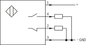 | PNP transistor outputs, load between switching outputs and GND | |||
Pinout  | 1 | V | 24 | |
2, 4 | Switching output | mA | 400 | |
3 | Earthing (GND) | V | 0 | |
The electric connection is realized via a 4-pole mating connector (separate order) with connection thread M12 x 1.
| High-performance version | Reduced power consumption “SO407” | |||
M12x1 plug-in connections 1) | K72L | |||
Available voltages 2) | V | 24 | ||
Limited switch-off voltage peak | V | -44 … -55 | ||
Voltage tolerance (nominal voltage) | % | ± 10 | ||
Power consumption | W | 30 | 8 | |
Duty cycle | % | 100 | ||
Switching time according to ISO 6403 | ON (without rectifier) | ms | 25 … 40 | - |
ON (with rectifier) | ms | 30 … 55 | - | |
ON (spool symbol “C”) | ms | - | 50 | |
ON (spool symbol “U”) | ms | - | 55 | |
OFF (without rectifier) | ms | 10 … 15 | - | |
OFF (with rectifier) | ms | 35 … 55 | - | |
OFF (spool symbol “C”) | ms | - | 50 | |
OFF (spool symbol “U”) | ms | - | 15 | |
Maximum switching frequency | Standard | 1/h | 15000 | 7200 |
Protection class according to EN 60529 3) | IP40 | |||
Protection class according to DIN EN 61140 | III | |||
Maximum coil temperature | °C | 150 4) | 110 5) | |
| 1) | Mating connectors according to IEC 60947-5-2, separate order, see data sheet 08006 |
| 2) | Connection to functional low voltage with secure separation only = PELV/SELV |
| 3) | Only with the use of the mating connectors indicated by us and with correct installation. |
| 4) | Due to the surface temperatures of the solenoid coils, the standards ISO 13732-1 and EN 982 need to be adhered to! |
| 5) | Due to the surface temperatures occurring at the solenoid coils, the European standards ISO 13732-1 and EN 982 need to be adhered to. |
Size | 6 | ||
Weight | 2/2 directional seat valve | kg | 1.5 |
3/2 directional seat valve | kg | 1.5 | |
4/2 directional seat valve | kg | 2.3 | |
Installation position | any | ||
Ambient temperature range | NBR seals | °C | -30 … +50 |
FKM seals | °C | -20 … +50 | |
Size | 6 | ||
Maximum operating pressure | Port P | bar | 420 630 |
Port A | bar | 420 630 | |
Port B | bar | 420 630 | |
Maximum flow | l/min | 25 | |
Hydraulic fluid | see table | ||
Hydraulic fluid temperature range | NBR seals | °C | -30 … +80 |
FKM seals | °C | -20 … +80 | |
Viscosity range | mm²/s | 2.8 … 500 | |
Maximum admissible degree of contamination of the hydraulic fluid, cleanliness class according to ISO 4406 (c) 1) | Class 20/18/15 according to ISO 4406 (c) | ||
| 1) | The cleanliness classes specified for the components must be adhered to in hydraulic systems. Effective filtration prevents faults and simultaneously increases the life cycle of the components. For the selection of the filters, see www.boschrexroth.com/filter. |
Hydraulic fluid | Classification | Suitable sealing materials | Standards | |
Mineral oils | HL, HLP, HLPD, HVLP, HVLPD | NBR, FKM | DIN 51524 | |
Bio-degradable | Insoluble in water | HETG | NBR, FKM | VDMA 24568 |
HEES | FKM | |||
Soluble in water | HEPG | FKM | VDMA 24568 | |
Containing water | Water-free | HFDU, HFDR | FKM | ISO 12922 |
Containing water | HFC (Fuchs Hydrotherm 46M, Petrofer Ultra Safe 620) | NBR, HNBR | ISO 12922 | |
Important information on hydraulic fluids!
Flame-resistant – containing water:
| ||||
Voltage type | Direct voltage | AC voltage | ||
Available voltages | V | 12 / 24 / 42 / 96 / 110 / 205 / 220 1) | 110 / 120 / 230 | |
Voltage tolerance (nominal voltage) | % | ± 10 | ||
Power consumption | W | 30 | ||
Duty cycle | % | 100 | ||
Switching time according to ISO 6403 | ON (without rectifier) | ms | 25 … 40 | |
ON (with rectifier) | ms | 30 … 55 | ||
OFF (without rectifier) | ms | 10 … 15 | ||
OFF (with rectifier) | ms | 35 … 55 | ||
Maximum switching frequency | Operating pressure ≤350 bar | 1/h | 15000 | |
Operating pressure >350 bar | 1/h | 3600 | ||
Protection class according to EN 60529 | IP65 (If a suitable and a correctly mounted mating connector are used.) | |||
Maximum surface temperature of the coil 2) | °C | 120 | ||
| 1) | Special voltages available upon request |
| 2) | Surface temperature > 50 °C, provide contact protection. |
In the electrical connection, the protective earthing conductor (PE, grounded) is to be connected in accordance with the stipulations.
Connection voltage (DC voltage) | V | 24 | ||
Voltage tolerance (connection voltage) | +30 %/-15 % | |||
Admissible residual ripple | % | ≤ 10 | ||
Max. load capacity | mA | 400 | ||
Switching outputs | PNP transistor outputs, load between switching outputs and GND | |||
Pinout | 1 | V | 24 | |
2, 4 | Switching output | mA | 400 | |
3 | Earthing (GND) | V | 0 | |
The electric connection is realized via a 4-pole mating connector (separate order) with connection thread M12 x 1.
| High-performance version | Reduced power consumption “SO407” | |||
M12x1 plug-in connections 1) | K72L | |||
Available voltages 2) | V | 24 | ||
Limited switch-off voltage peak | V | -44 … -55 | ||
Voltage tolerance (nominal voltage) | % | ± 10 | ||
Power consumption | W | 30 | 8 | |
Duty cycle | % | 100 | ||
Switching time according to ISO 6403 | ON (without rectifier) | ms | 25 … 40 | - |
ON (with rectifier) | ms | 30 … 55 | - | |
ON (spool symbol “C”) | ms | - | 50 | |
ON (spool symbol “U”) | ms | - | 55 | |
OFF (without rectifier) | ms | 10 … 15 | - | |
OFF (with rectifier) | ms | 35 … 55 | - | |
OFF (spool symbol “C”) | ms | - | 50 | |
OFF (spool symbol “U”) | ms | - | 15 | |
Maximum switching frequency | Standard | 1/h | 15000 | 7200 |
Protection class according to EN 60529 3) | IP40 | |||
Protection class according to DIN EN 61140 | III | |||
Maximum coil temperature | °C | 150 4) | 110 5) | |
| 1) | Mating connectors according to IEC 60947-5-2, separate order, see data sheet 08006 |
| 2) | Connection to functional low voltage with secure separation only = PELV/SELV |
| 3) | Only with the use of the mating connectors indicated by us and with correct installation. |
| 4) | Due to the surface temperatures of the solenoid coils, the standards ISO 13732-1 and EN 982 need to be adhered to! |
| 5) | Due to the surface temperatures occurring at the solenoid coils, the European standards ISO 13732-1 and EN 982 need to be adhered to. |
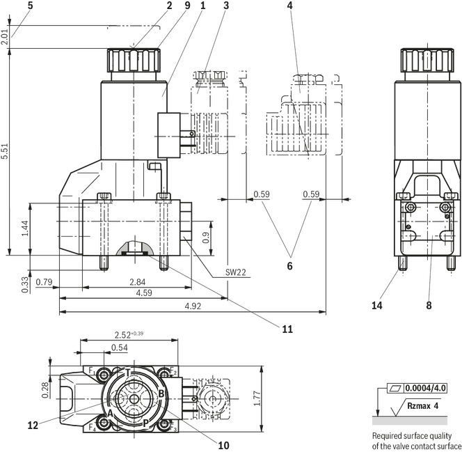
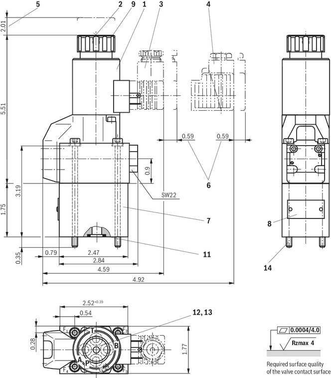
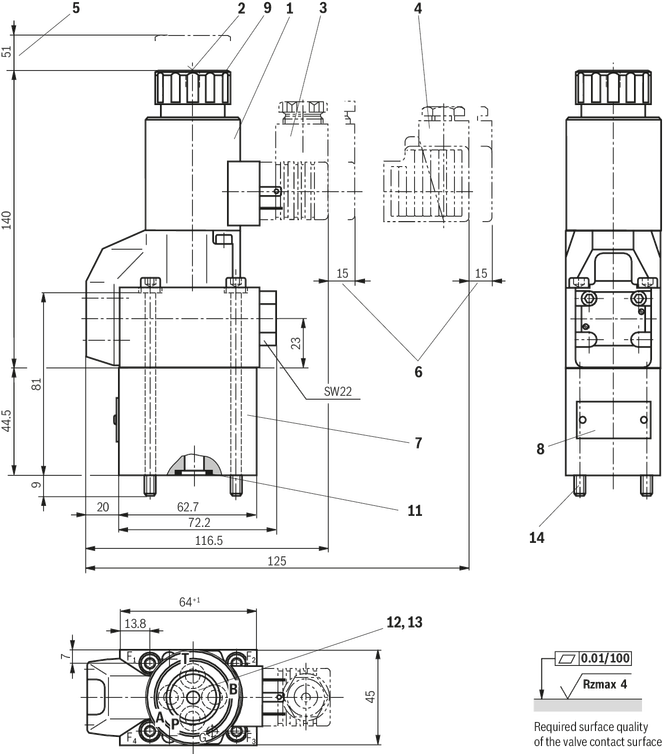
Dimensions in mm

Dimensions in mm

1 | Solenoid “a” |
2 | Concealed manual override “N9” |
3 | Mating connector without circuitry (separate order) |
4 | Mating connector without circuitry (separate order) |
5 | Space required to remove the coil |
6 | Space required to remove the mating connector |
8 | Name plate |
9 | Mounting nut, tightening torque MA = 4 Nm |
10 |
|
11 | Identical seal rings for ports A, B, and T; seal ring for port P |
13 | Porting pattern according to ISO 4401-03-02-0-05 (with locating hole for locking pin ISO 8752-3x8-St, material no. R900005694, included in the scope of delivery) |
14 | Valve mounting screws |
Dimensions in mm

Dimensions in mm
1 | Solenoid “a” |
2 | Concealed manual override “N9” |
3 | Mating connector without circuitry (separate order) |
4 | Mating connector without circuitry (separate order) |
5 | Space required to remove the coil |
6 | Space required to remove the mating connector |
8 | Name plate |
9 | Mounting nut, tightening torque MA = 4 Nm |
10 |
|
11 | Identical seal rings for ports A, B, and T; seal ring for port P |
12 | Porting pattern according to DIN 24340, form A |
14 | Valve mounting screws |
Dimensions in mm
Dimensions in mm
1 | Solenoid “a” |
2 | Concealed manual override “N9” |
3 | Mating connector without circuitry (separate order) |
4 | Mating connector with circuitry (separate order, see page data separate order, see data sheet 08006) |
5 | Space required to remove the coil |
6 | Space required to remove the mating connector |
7 | Plus-1 plate |
8 | Name plate |
9 | Mounting nut, tightening torque MA = 4 Nm |
11 | Identical seal rings for ports A, B, and T; seal ring for port P |
12 | Porting pattern according to DIN 24340, form A |
13 | Porting pattern according to ISO 4401-03-02-0-05 (with locating hole for locking pin ISO 8752-3x8-St, material no. R900005694, included in the scope of delivery) |
14 | Valve mounting screws |
Valve mounting screws (separate order)
2/2 and 3/2 directional seat valve
Version “420”:
4 hexagon socket head cap screws metric
ISO 4762 - M5 x 45 - 10.9-flZn-240h-L
(friction coefficient μtotal = 0.09 to 0.14);
tightening torque MA = 7 Nm ± 10 %,
material no. R913000140
or
4 hexagon socket head cap screws
ISO 4762 - M5 x 45 - 10.9 1)
(friction coefficient μges = 0.12 to 0.17);
tightening torque MA = 8,1 Nm ± 10 %
4 hexagon socket head cap screws UNC
10-24 UNC x 1 3/4” ASTM-574 1)
(friction coefficient μtotal = 0.19 to 0.24 according to ASTM-574);
tightening torque MA = 11 Nm ± 15 %,
(friction coefficient μtotal = 0.12 to 0.17 according to ISO 4762);
tightening torque MA = 8 Nm ± 10 %,
material no. R978802649
version “630”:
4 hexagon socket head cap screws metric
ISO 4762 - M6 x 45 - 10.9-flZn-240h-L
(friction coefficient μtotal = 0.09 to 0.14);
tightening torque MA = 12,5 Nm ± 10 %,
material no. metric R913000258
or
4 hexagon socket head cap screws
ISO 4762 - M6 x 45 - 10.9 1)
(friction coefficient μtotal = 0.12 to 0.17);
tightening torque MA = 15,5 Nm ± 10 %
4 hexagon socket head cap screws UNC
1/4-20 UNC x 1 3/4” ASTM-574 1)
(friction coefficient μtotal = 0.19 to 0.24 according to ASTM-574);
tightening torque MA = 20 Nm ± 15 %,
(friction coefficient μtotal = 0.12 to 0.17 according to ISO 4762);
tightening torque MA = 14 Nm ± 10 %,
material no. R978800711
4/2 directional seat valve
version “420”:
4 hexagon socket head cap screws metric
ISO 4762 - M5 x 90 - 10.9-flZn-240h-L
(friction coefficient μtotal = 0.09 to 0.14);
tightening torque MA = 7 Nm ± 10 %,
material no. R913000222
oder
4 hexagon socket head cap screws
ISO 4762 - M5 x 90 - 10.9 1)
(friction coefficient μtotal = 0.12 to 0.17);
tightening torque MA = 8,1 Nm ± 10 %
4 hexagon socket head cap screws UNC
10-24 UNC x 3 1/2” 1)
(friction coefficient μtotal = 0.19 to 0.24 according to ASTM-574);
tightening torque MA = 11 Nmv± 15 %,
(friction coefficient μtotal = 0.12 to 0.17 according to ISO 4762);
tightening torque MA = 8 Nm ± 10 %,
material no. R978800696
version “630”:
4 hexagon socket head cap screws metric
ISO 4762 - M6 x 90 - 10.9-flZn-240h-L
(friction coefficient μtotal = 0.09 to 0.14);
tightening torque MA = 12,5 Nm ± 10 %,
material no. R913000259
or
4 hexagon socket head cap screws
ISO 4762 - M6 x 90 - 10.9 1)
(friction coefficient μtotal = 0.12 to 0.17);
tightening torque MA = 15,5 Nm ± 10 %
4 hexagon socket head cap screws UNC
1/4-20 UNC x 3 1/2” 1)
(friction coefficient μtotal = 0.19 to 0.24);
tightening torque MA = 20 Nm ± 15 %,
(friction coefficient μtotal = 0.12 to 0.17);
tightening torque MA = 14 Nm ± 10 %,
material no. R978800717
1) Not included in the Rexroth delivery range
Size | H |
mm | |
| 6 | 23 |
| 10 | 32.5 |
The dimensions are nominal dimensions which are subject to tolerances.
Dimensions in mm

Dimensions in mm

Dimensions in mm

Dimensions in mm

| 1) | For dimensions, see valve dimensions |
Dimensions in mm
Dimensions in mm
1 | Solenoid “a” |
2 | Concealed manual override “N9” |
3 | Mating connector without circuitry (separate order) |
4 | Mating connector without circuitry (separate order) |
5 | Space required to remove the coil |
6 | Space required to remove the mating connector |
8 | Name plate |
9 | Mounting nut, tightening torque MA = 4 Nm |
10 |
|
11 | Identical seal rings for ports A, B, and T; seal ring for port P |
13 | Porting pattern according to ISO 4401-03-02-0-05 (with locating hole for locking pin ISO 8752-3x8-St, material no. R900005694, included in the scope of delivery) |
14 | Valve mounting screws |
Dimensions in mm
Dimensions in mm
1 | Solenoid “a” |
2 | Concealed manual override “N9” |
3 | Mating connector without circuitry (separate order) |
4 | Mating connector without circuitry (separate order) |
5 | Space required to remove the coil |
6 | Space required to remove the mating connector |
8 | Name plate |
9 | Mounting nut, tightening torque MA = 4 Nm |
10 |
|
11 | Identical seal rings for ports A, B, and T; seal ring for port P |
12 | Porting pattern according to DIN 24340, form A |
14 | Valve mounting screws |
Dimensions in mm
Dimensions in mm
1 | Solenoid “a” |
2 | Concealed manual override “N9” |
3 | Mating connector without circuitry (separate order) |
4 | Mating connector with circuitry (separate order, see page data separate order, see data sheet 08006) |
5 | Space required to remove the coil |
6 | Space required to remove the mating connector |
7 | Plus-1 plate |
8 | Name plate |
9 | Mounting nut, tightening torque MA = 4 Nm |
11 | Identical seal rings for ports A, B, and T; seal ring for port P |
12 | Porting pattern according to DIN 24340, form A |
13 | Porting pattern according to ISO 4401-03-02-0-05 (with locating hole for locking pin ISO 8752-3x8-St, material no. R900005694, included in the scope of delivery) |
14 | Valve mounting screws |
Valve mounting screws (separate order)
2/2 and 3/2 directional seat valve
Version “420”:
4 hexagon socket head cap screws metric
ISO 4762 - M5 x 45 - 10.9-flZn-240h-L
(friction coefficient μtotal = 0.09 to 0.14);
tightening torque MA = 7 Nm ± 10 %,
material no. R913000140
or
4 hexagon socket head cap screws
ISO 4762 - M5 x 45 - 10.9 1)
(friction coefficient μges = 0.12 to 0.17);
tightening torque MA = 8,1 Nm ± 10 %
4 hexagon socket head cap screws UNC
10-24 UNC x 1 3/4” ASTM-574 1)
(friction coefficient μtotal = 0.19 to 0.24 according to ASTM-574);
tightening torque MA = 11 Nm ± 15 %,
(friction coefficient μtotal = 0.12 to 0.17 according to ISO 4762);
tightening torque MA = 8 Nm ± 10 %,
material no. R978802649
version “630”:
4 hexagon socket head cap screws metric
ISO 4762 - M6 x 45 - 10.9-flZn-240h-L
(friction coefficient μtotal = 0.09 to 0.14);
tightening torque MA = 12,5 Nm ± 10 %,
material no. metric R913000258
or
4 hexagon socket head cap screws
ISO 4762 - M6 x 45 - 10.9 1)
(friction coefficient μtotal = 0.12 to 0.17);
tightening torque MA = 15,5 Nm ± 10 %
4 hexagon socket head cap screws UNC
1/4-20 UNC x 1 3/4” ASTM-574 1)
(friction coefficient μtotal = 0.19 to 0.24 according to ASTM-574);
tightening torque MA = 20 Nm ± 15 %,
(friction coefficient μtotal = 0.12 to 0.17 according to ISO 4762);
tightening torque MA = 14 Nm ± 10 %,
material no. R978800711
4/2 directional seat valve
version “420”:
4 hexagon socket head cap screws metric
ISO 4762 - M5 x 90 - 10.9-flZn-240h-L
(friction coefficient μtotal = 0.09 to 0.14);
tightening torque MA = 7 Nm ± 10 %,
material no. R913000222
oder
4 hexagon socket head cap screws
ISO 4762 - M5 x 90 - 10.9 1)
(friction coefficient μtotal = 0.12 to 0.17);
tightening torque MA = 8,1 Nm ± 10 %
4 hexagon socket head cap screws UNC
10-24 UNC x 3 1/2” 1)
(friction coefficient μtotal = 0.19 to 0.24 according to ASTM-574);
tightening torque MA = 11 Nmv± 15 %,
(friction coefficient μtotal = 0.12 to 0.17 according to ISO 4762);
tightening torque MA = 8 Nm ± 10 %,
material no. R978800696
version “630”:
4 hexagon socket head cap screws metric
ISO 4762 - M6 x 90 - 10.9-flZn-240h-L
(friction coefficient μtotal = 0.09 to 0.14);
tightening torque MA = 12,5 Nm ± 10 %,
material no. R913000259
or
4 hexagon socket head cap screws
ISO 4762 - M6 x 90 - 10.9 1)
(friction coefficient μtotal = 0.12 to 0.17);
tightening torque MA = 15,5 Nm ± 10 %
4 hexagon socket head cap screws UNC
1/4-20 UNC x 3 1/2” 1)
(friction coefficient μtotal = 0.19 to 0.24);
tightening torque MA = 20 Nm ± 15 %,
(friction coefficient μtotal = 0.12 to 0.17);
tightening torque MA = 14 Nm ± 10 %,
material no. R978800717
1) Not included in the Rexroth delivery range
Size | H |
mm | |
| 6 | 23 |
| 10 | 32.5 |
The dimensions are nominal dimensions which are subject to tolerances.
Dimensions in mm
Dimensions in mm
Dimensions in mm
Dimensions in mm
| 1) | For dimensions, see valve dimensions |


