| Availability: | |
|---|---|
| Quantity: | |

ZDC 10 P-2X/M
Rexroth
R900488023
Sandwich plate valve
Porting pattern according to ISO 4401
Load compensation in channel P → A or P → B by installed shuttle valve
2-way version "P"
3-way version "PT" (NG10 ... 25)
Flow control in case of interaction with proportional directional valve
Sandwich plate valve
Porting pattern according to ISO 4401
Load compensation in channel P → A or P → B by installed shuttle valve
2-way version "P"
3-way version "PT" (NG10 ... 25)
Flow control in case of interaction with proportional directional valve
01 | 02 | 03 | 04 | 05 | 06 | 07 | 08 | 09 | ||
Z | DC | - | 2X | / | * |
01 | Sandwich plate valve | Z |
02 | Meter-in pressure compensator | DC |
03 | Size 10 | 10 |
Size 16 | 16 | |
Size 25 | 25 | |
Size 32 | 32 | |
04 | 2-way version (pressure reducing function) | P |
3-way version (pressure limiting function) | PT | |
05 | Component series 20 ... 29 (20 ... 29: unchanged installation and connection dimensions) - Size 6 | 2X |
06 | Internal pilot oil supply | no code |
External pilot oil supply | X | |
Pilot oil supply extern, port X closed on the component side (only NG10) | XL | |
07 | Without special type of protection | no code |
Sea water-resistant | J | |
Seal material | ||
08 | NBR seals | M |
FKM seals | V | |
09 | Further details in the plain text | * |
Nenngröße | 10 | 16 | 25 | 32 | |
Geräteserie | 2X | ||||
Einbaulage | Any | ||||
Masse | kg | 3 | 3.5 | 8.9 | 64.7 |
Maximaler Betriebsdruck | bar | 350 | ||||
Maximaler Betriebsdruck | Anschluss A | bar | 350 | |||
Anschluss B | bar | 350 | ||||
Port P | bar | 350 | ||||
Port T | bar | 250 | ||||
Port Y 1) | bar | 150 | ||||
Betriebsdruckbereich | Anschluss X | bar | 30 ... 100 | |||
Maximum flow | l/min | 85 | 150 | 325 | 520 | |
Druckflüssigkeit | see table | |||||
Druckflüssigkeitstemperaturbereich | °C | -20 … +70 | ||||
Maximal zulässiger Verschmutzungsgrad der Druckflüssigkeit; Reinheitsklasse nach ISO 4406 (c) 2) | Class 20/18/15 according to ISO 4406 (c) | |||||
Viskositätsbereich | mm²/s | 15 … 380 | ||||
| 1) | up to 30 bar in connection with pilot-operated proportional directional valve |
| 2) | The cleanliness classes specified for the components must be adhered to in hydraulic systems. Effective filtration prevents faults and simultaneously increases the life cycle of the components. For the selection of the filters, see www.boschrexroth.com/filter. |
Hydraulic fluid | Classification | Suitable sealing materials | Standards |
Mineral oils and related hydrocarbons | HL, HLP, HLPD, HVLP, HVLPD | NBR | DIN 51524 |
Important information on hydraulic fluids: For more information and data on the use of other hydraulic fluids please contact us. There may be limitations regarding the technical valve data (temperature, pressure range, life cycle, maintenance intervals, etc.). | |||
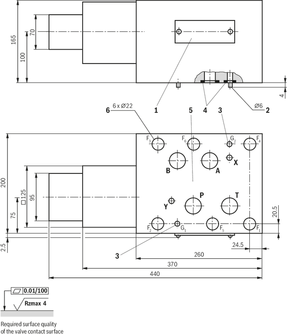
Dimensions in mm

1 | Name plate |
4 | Identical seal rings for ports A, B, P, and T Identical seal rings for ports X and Y (plate side) |
5 | Porting pattern according to ISO 4401-05-05-0-05 |
6 | Valve mounting bores |
Valve mounting screws (separate order) | |
Dimensions in mm

1 | Name plate |
2 | Locating pin |
3 | Bore for locating pin |
4 | Identical seal rings for ports A, B, P, and T Identical seal rings for ports X and Y (plate side) |
5 | Porting pattern according to ISO 4401-07-07-0-05 |
6 | Valve mounting bores |
Valve mounting screws (separate order) | |
Dimensions in mm

1 | Name plate |
2 | Locating pin |
3 | Bore for locating pin |
4 | Identical seal rings for ports A, B, P, and T Identical seal rings for ports X and Y (plate side) |
5 | Porting pattern according to ISO 4401-08-08-0-05 |
6 | Valve mounting bores |
Valve mounting screws (separate order) | |
Dimensions in mm
1 | Name plate |
2 | Locating pin |
3 | Bore for locating pin |
4 | Identical seal rings for ports A, B, P, and T Identical seal rings for ports X and Y (plate side) |
5 | Porting pattern according to ISO 4401-10-09-0-05 |
6 | Valve mounting bores |
Valve mounting screws (separate order) | |
Dimensions in mm
1 | Name plate |
4 | Identical seal rings for ports A, B, P, and T Identical seal rings for ports X and Y (plate side) |
5 | Porting pattern according to ISO 4401-05-05-0-05 |
6 | Valve mounting bores |
Valve mounting screws (separate order) | |
Dimensions in mm
1 | Name plate |
2 | Locating pin |
3 | Bore for locating pin |
4 | Identical seal rings for ports A, B, P, and T Identical seal rings for ports X and Y (plate side) |
5 | Porting pattern according to ISO 4401-07-07-0-05 |
6 | Valve mounting bores |
Valve mounting screws (separate order) | |
Dimensions in mm
1 | Name plate |
2 | Locating pin |
3 | Bore for locating pin |
4 | Identical seal rings for ports A, B, P, and T Identical seal rings for ports X and Y (plate side) |
5 | Porting pattern according to ISO 4401-08-08-0-05 |
6 | Valve mounting bores |
Valve mounting screws (separate order) | |
Dimensions in mm
1 | Name plate |
2 | Locating pin |
3 | Bore for locating pin |
4 | Identical seal rings for ports A, B, P, and T Identical seal rings for ports X and Y (plate side) |
5 | Porting pattern according to ISO 4401-10-09-0-05 |
6 | Valve mounting bores |
Valve mounting screws (separate order) | |
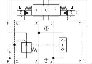
Valves of type ZDC are direct operated supply pressure compensators in 2- or 3-way version.
The are used for the load compensation as supply pressure compensator in channel P.
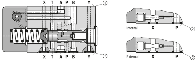
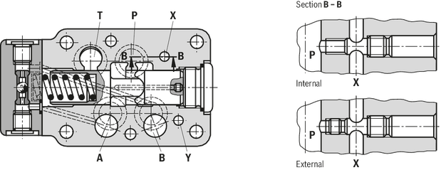
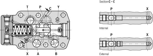
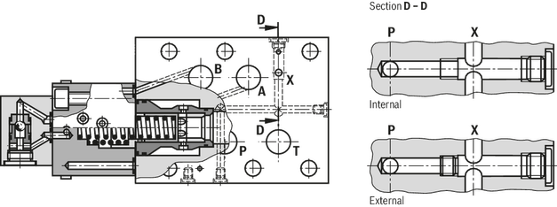
These valves basically consist of the housing (1), the control spool (2), compression spring (3) with spring plate (4) and the cover (5) with installed shuttle valve (6).
The compression spring (3) holds the control spool (2) in the opened position from P2 to P1 if the pressure differential P1 → A1 or P1 → B1 is smaller than 10 bar.
If the pressure differential exceeds 10 bar, the control spool (2) is moved to the left until the pressure differential is restored again.

In connection with the supply pressure compensator, the pilot-operated proportional directional valve is to be used with “external pilot oil supply“!
With external pilot oil supply, the connection to channel P is blocked. The pilot oil is sampled from a separate control circuit.
With internal pilot oil supply, the connection to channel P is open. The pilot oil is sampled upstream the throttle side of the pressure compensator (port X in the subplate is blocked).

Valves of type ZDC are direct operated supply pressure compensators in 2- or 3-way version.
The are used for the load compensation as supply pressure compensator in channel P.
These valves basically consist of the housing (1), the control spool (2), compression spring (3) with spring plate (4) and the cover (5) with installed shuttle valve (6).
The compression spring (3) holds the control spool (2) in the opened position from P2 to P1 if the pressure differential P1 → A1 or P1 → B1 is smaller than 10 bar.
If the pressure differential exceeds 10 bar, the control spool (2) is moved to the left until the pressure differential is restored again.
In connection with the supply pressure compensator, the pilot-operated proportional directional valve is to be used with “external pilot oil supply“!
With external pilot oil supply, the connection to channel P is blocked. The pilot oil is sampled from a separate control circuit.
With internal pilot oil supply, the connection to channel P is open. The pilot oil is sampled upstream the throttle side of the pressure compensator (port X in the subplate is blocked).


