| Availability: | |
|---|---|
| Quantity: | |

Z2FS10-5-3X/V
Rexroth
R900517812
Sandwich plate valve
Porting pattern according to ISO 4401-05-04-0-05
For the main or pilot flow limitation of 2 actuator ports.
3 adjustment types:
• Lockable rotary knob with scale
• Spindle with internal hexagon and scal
• Rotary knob with scale
Meter-in or meter-out throttling
Corrosion-protected design
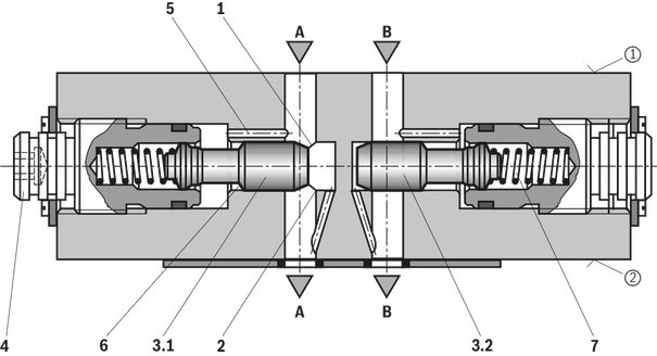
The valve type Z2FS 10 is a throttle check valve in sandwich plate design. It is used for the main or pilot flow limitation of one or two actuator ports.
Two throttle check valves aligned symmetrically to each other limit flows in one direction and allow free return flow in the opposite direction.
In case of supply throttling, the hydraulic fluid is directed through channel A1 via throttling point (1) formed by the control edge (2) and the throttle spool (3.1) to actuator A2. The throttle spool (3.1) can be axially adjusted via the spindle (4) for adjustment of the throttling point (1).
Simultaneously, the hydraulic fluid in channel A1 is directed via the bore (5) to the piston side (6). The active pressure and the spring force retain the throttle spool (3.1) in throttle position.
The hydraulic fluid return flow from actuator B2 displaces the throttle spool (3.2) against the spring (7) and enables the unobstructed flow as check valve. Depending on the installation position, the throttling effect may occur in supply or discharge.
Main flow limitation
For actuator velocity adjustment (main flow limitation), the throttle check valve is installed between the directional valve and the subplate.
Pilot flow limitation
With pilot-operated directional valves, the throttle check valve can be applied for switching time adjustment (pilot flow limitation). In this case, it is installed between the pilot control valve and the main valve.
Supply throttling
01 | 02 | 03 | 04 | 05 | 06 | 07 | 08 | 09 | 10 | ||
Z2FS | 10 | – | 3X | / | * |
01 | Throttle check valve, sandwich plate design | Z2FS |
02 | Size 10 | 10 |
03 | Throttle check valve side A and B | – 1) |
Throttle check valve side A | A | |
Throttle check valve side B | B | |
Adjustment type | ||
04 | Lockable rotary knob with scale | 3 2) |
Spindle with internal hexagon and scale | 5 | |
Rotary knob with scale | 7 | |
05 | Component series 30 ... 39 (30 ... 39: unchanged installation and connection dimensions) | 3X |
06 | With two throttle check valves, supply or discharge throttling (the valve can be rotated) | no code |
Supply throttling on side A (…A.–3X/S) | S | |
Supply throttling on side B (…B.–3X/S) | ||
Discharge throttling on side A (…A.–3X/S2) | S2 | |
Discharge throttling on side B (…B.–3X/S2) | ||
Corrosion resistance | ||
07 | None | no code |
Improved corrosion protection (240 h salt spray test according to EN ISO 9227) | J3 | |
Seal material | ||
08 | NBR seals | no code |
FKM seals | V | |
Observe compatibility of seals with hydraulic fluid used. (Other seals upon request) | ||
Pilot oil duct | ||
09 | None | no code |
Via channel X and Y | SO30 | |
10 | Further details in the plain text | * |
| 1) | Identical adjustment types on sides A and B. |
| 2) | Key with material no. R900008158 is included in the scope of delivery. |
Size | 10 | ||
Weight (approx.) | kg | 3.1 | |
Installation position | any | ||
Ambient temperature range | NBR seals | °C | -30 … +80 |
FKM seals | °C | -20 … +80 | |
Size | 10 | ||
Maximum operating pressure | bar | 315 | |
Maximum flow | l/min | 160 | |
Hydraulic fluid | see table | ||
Hydraulic fluid temperature range | NBR seals | °C | -30 … +80 |
FKM seals | °C | -20 … +80 | |
Viscosity range | mm²/s | 10 … 800 | |
Maximum admissible degree of contamination of the hydraulic fluid 1) | Class 20/18/15 according to ISO 4406 (c) | ||
| 1) | The cleanliness classes specified for the components must be adhered to in hydraulic systems. Effective filtration prevents faults and simultaneously increases the life cycle of the components. For the selection of the filters, see www.boschrexroth.com/filter. |
Hydraulic fluid | Classification | Suitable sealing materials | Standards | Data sheet | |
Mineral oil | HL, HLP | FKM, NBR | DIN 51524 | 90220 | |
Bio-degradable 1) | Insoluble in water | HETG | FKM | ISO 15380 | 90221 |
HEES | FKM | ||||
Soluble in water | HEPG | FKM | ISO 15380 | ||
Flame-resistant | Water-free | HFDU (glycol base) | FKM | ISO 12922 | 90222 |
HFDU (ester base) 1) | FKM | ||||
Containing water | HFC (Fuchs Hydrotherm 46M, Petrofer Ultra Safe 620) | NBR | ISO 12922 | 90223 | |
Important information on hydraulic fluids:
| |||||
| 1) | Not recommended for corrosion-protected version "J3" (contains zinc) |
Size | 10 | ||
Weight (approx.) | kg | 3.1 | |
Installation position | any | ||
Ambient temperature range | NBR seals | °C | -30 … +80 |
FKM seals | °C | -20 … +80 | |
Size | 10 | ||
Maximum operating pressure | bar | 315 | |
Maximum flow | l/min | 160 | |
Hydraulic fluid | see table | ||
Hydraulic fluid temperature range | NBR seals | °C | -30 … +80 |
FKM seals | °C | -20 … +80 | |
Viscosity range | mm²/s | 10 … 800 | |
Maximum admissible degree of contamination of the hydraulic fluid 1) | Class 20/18/15 according to ISO 4406 (c) | ||
| 1) | The cleanliness classes specified for the components must be adhered to in hydraulic systems. Effective filtration prevents faults and simultaneously increases the life cycle of the components. For the selection of the filters, see www.boschrexroth.com/filter. |
Hydraulic fluid | Classification | Suitable sealing materials | Standards | Data sheet | |
Mineral oil | HL, HLP | FKM, NBR | DIN 51524 | 90220 | |
Bio-degradable 1) | Insoluble in water | HETG | FKM | ISO 15380 | 90221 |
HEES | FKM | ||||
Soluble in water | HEPG | FKM | ISO 15380 | ||
Flame-resistant | Water-free | HFDU (glycol base) | FKM | ISO 12922 | 90222 |
HFDU (ester base) 1) | FKM | ||||
Containing water | HFC (Fuchs Hydrotherm 46M, Petrofer Ultra Safe 620) | NBR | ISO 12922 | 90223 | |
Important information on hydraulic fluids:
| |||||
| 1) | Not recommended for corrosion-protected version "J3" (contains zinc) |
(dimensions in mm)
Dimensions in mm

1 | Name plate |
2 | Adjustment type “5” – spindle for changing the flow cross-section (internal hexagon SW8)
|
3 | Adjustment type "3" |
4 | Adjustment type "7" |
5 | 4 through holes for valve mounting |
6 | Identical seal rings for ports A, B, P, TA, TB |
7 | R-ring plate |
8 | Modification from supply to discharge throttling is realized by rotation of the device around axis "X" – "X" (version "–" only) |
9 | Space required to remove the key |
10 | Porting pattern according to ISO 4401-05-04-0-05 |
11 | Version "J" |
(dimensions in mm)
Dimensions in mm

1 | Name plate |
2 | Adjustment type “5” – spindle for changing the flow cross-section (internal hexagon SW8)
|
3 | Adjustment type "3" |
4 | Adjustment type "7" |
5 | 4 through holes for valve mounting |
6 | Identical seal rings for ports A, B, P, TA, TB |
7 | R-ring plate |
9 | Space required to remove the key |
10 | Porting pattern according to ISO 4401-05-04-0-05 |
11 | Version "J" |
Notices:
Deviating from ISO 4401, port T is called TA and port T1 is called TB in this data sheet.
The dimensions are nominal dimensions which are subject to tolerances.
Version "SO30" is shown. The standard version does not have ports X and Y.
Valve mounting screws (separate order)
4 hexagon socket head cap screws ISO 4762 - M6 - 10.9
4 hexagon socket head cap screws 1/4-2 UNC
Notice:
Length and tightening torque of the valve mounting screws must be calculated according to the components mounted under and over the sandwich plate valve.
Dimensions in mm

Dimensions in mm

(dimensions in mm)
Dimensions in mm
1 | Name plate |
2 | Adjustment type “5” – spindle for changing the flow cross-section (internal hexagon SW8)
|
3 | Adjustment type "3" |
4 | Adjustment type "7" |
5 | 4 through holes for valve mounting |
6 | Identical seal rings for ports A, B, P, TA, TB |
7 | R-ring plate |
8 | Modification from supply to discharge throttling is realized by rotation of the device around axis "X" – "X" (version "–" only) |
9 | Space required to remove the key |
10 | Porting pattern according to ISO 4401-05-04-0-05 |
11 | Version "J" |
(dimensions in mm)
Dimensions in mm
1 | Name plate |
2 | Adjustment type “5” – spindle for changing the flow cross-section (internal hexagon SW8)
|
3 | Adjustment type "3" |
4 | Adjustment type "7" |
5 | 4 through holes for valve mounting |
6 | Identical seal rings for ports A, B, P, TA, TB |
7 | R-ring plate |
9 | Space required to remove the key |
10 | Porting pattern according to ISO 4401-05-04-0-05 |
11 | Version "J" |
Notices:
Deviating from ISO 4401, port T is called TA and port T1 is called TB in this data sheet.
The dimensions are nominal dimensions which are subject to tolerances.
Version "SO30" is shown. The standard version does not have ports X and Y.
Valve mounting screws (separate order)
4 hexagon socket head cap screws ISO 4762 - M6 - 10.9
4 hexagon socket head cap screws 1/4-2 UNC
Notice:
Length and tightening torque of the valve mounting screws must be calculated according to the components mounted under and over the sandwich plate valve.
Dimensions in mm
Dimensions in mm


