Z2DB10VC1-4X/200
Rexroth
R900435042
4/3-, 4/2- or 3/2-way version
Porting pattern according to ISO 4401-05-04-0-05
High-power solenoid, optionally rotatable by 90°
Electric connection as single or central connection
Use optionally with PWM connector (fast switching amplifier, energy reduction)
Optional auxiliary operating device
CE conformity according to the Low-Voltage Directive 2006/95/EC for electrical voltages >50 VAC or > 75VDC
Solenoid coil with UR approval UL 429
Approval according to CSA C22.2 no. 139-10, optional
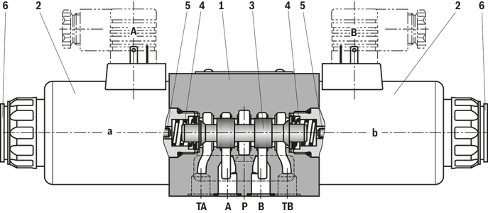
The directional valve type WE is a solenoid-actuated directional spool valve that can be used as electro-magnetic component. It controls the start, stop and direction of a flow.
The directional valve basically consists of housing (1), one or two electronic solenoids (2), control spool (3), and the return springs (4).
In the de-energized condition, the control spool (3) is held in the central position or in the initial position by the return springs (4) (except for version "O").
If the wet-pin electronic solenoid (2) is energized, the control spool (3) moves out of its rest position into the required end position. In this way, the required direction of flow according to the selected symbol is released.
After the electronic solenoid (2) has been switched off, the control spool (3) is pushed back into its central position or into its initial position (except for valves with "OF" detent and valves without type "O" spring).
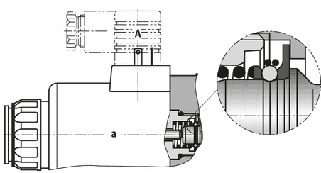
A manual override (6) allows for the manual switching of the valve without solenoid energization.
To ensure proper functioning, make sure that the pressure chamber of the solenoid is filled with oil.
For more functions, refer to the functional description.
Throttle insert "B.."
Using a throttle insert (7) in channels P, A, B or T, the flow resistance at the valve can be increased. Its use is required when, due to prevailing operating conditions, flows occur during the switching processes, which exceed the performance limit of the valve.

Without spring return “O” (only possible with symbols A, C and D)
This version is a directional valve with 2 spool positions and 2 electronic solenoids without detent. The valve without spring return at the control spool (3) does not have a defined basic position in the de-energized condition.
Without spring return with detent “OF” (only possible with symbols A, C and D)
This version is a directional valve with 2 spool positions and 2 electronic solenoids with detent. The detents are used to lock the control spool (3) in the relevant spool position. During operation, continuous application of current to the electronic solenoid can thus be omitted which contributes to energy-efficient operation.
Notice!
Pressure peaks in the tank line to two or several valves can result in unwanted movements of the control spool in the case of valves with detent! We therefore recommend that separate return lines be provided or a check valve installed in the tank line.
The directional valve type WE is a solenoid-actuated directional spool valve that can be used as electro-magnetic component. It controls the start, stop and direction of a flow.
The directional valve basically consists of housing (1), one or two electronic solenoids (2), control spool (3), and the return springs (4).
In the de-energized condition, the control spool (3) is held in the central position or in the initial position by the return springs (4) (except for version "O").
If the wet-pin electronic solenoid (2) is energized, the control spool (3) moves out of its rest position into the required end position. In this way, the required direction of flow according to the selected symbol is released.
After the electronic solenoid (2) has been switched off, the control spool (3) is pushed back into its central position or into its initial position (except for valves with "OF" detent and valves without type "O" spring).
A manual override (6) allows for the manual switching of the valve without solenoid energization.
To ensure proper functioning, make sure that the pressure chamber of the solenoid is filled with oil.
For more functions, refer to the functional description.
Throttle insert "B.."
Using a throttle insert (7) in channels P, A, B or T, the flow resistance at the valve can be increased. Its use is required when, due to prevailing operating conditions, flows occur during the switching processes, which exceed the performance limit of the valve.
Without spring return “O” (only possible with symbols A, C and D)
This version is a directional valve with 2 spool positions and 2 electronic solenoids without detent. The valve without spring return at the control spool (3) does not have a defined basic position in the de-energized condition.
Without spring return with detent “OF” (only possible with symbols A, C and D)
This version is a directional valve with 2 spool positions and 2 electronic solenoids with detent. The detents are used to lock the control spool (3) in the relevant spool position. During operation, continuous application of current to the electronic solenoid can thus be omitted which contributes to energy-efficient operation.
Notice!
Pressure peaks in the tank line to two or several valves can result in unwanted movements of the control spool in the case of valves with detent! We therefore recommend that separate return lines be provided or a check valve installed in the tank line.
01 | 02 | 03 | 04 | 05 | 06 | 07 | 08 | 09 | 10 | 11 | 12 | 13 | 14 | 15 | 16 | 17 | 18 | 19 | 20 | 21 | 22 | |
DB | 5X | / | * |
01 | Pressure relief valve | DB |
02 | Without directional valve | no code |
03 | Pilot-operated valve (complete) | no code |
Pilot control valve without main spool insert (do not enter any size) | C | |
Pilot control valve with main spool insert (enter size 10 or 30) | C | |
Pilot control valve without main spool insert for subplate mounting (do not enter any size) | T 1) | |
04 | Size 10 | |
Subplate mounting "no code" | 10 | |
Threaded connection "G" | 10 (G1/2) | |
Size 16 | ||
Threaded connection "G" | 15 (G3/4) | |
Size 25 | ||
Subplate mounting "no code" | 20 | |
Threaded connection "G" | 20 (G1) | |
Threaded connection "G" | 25 (G1 1/4) | |
Size 32 | ||
Subplate mounting "no code" | 30 | |
Threaded connection "G" | 30 (G1 1/2) | |
05 | Without directional valve | no code |
Type of connection | ||
06 | Subplate mounting or cartridge valve | no code |
For threaded connection | G | |
Adjustment type for pressure adjustment | ||
07 | Rotary knob (not for version "C" and "T") | 1 |
Sleeve with hexagon and protective cap | 2 | |
Lockable rotary knob with scale | 3 2) | |
Rotary knob with scale | 7 | |
08 | Main spool Ø24 mm (all sizes) | – |
Main spool Ø28 mm (only for NG32) | N | |
09 | Component series 50 … 59 (50 … 59: unchanged installation and connection dimensions) | 5X |
10 | Set pressure up to 50 bar | 50 |
Set pressure up to 100 bar | 100 | |
Set pressure up to 200 bar | 200 | |
Set pressure up to 315 bar | 315 | |
Set pressure up to 350 bar | 350 | |
Pilot oil flow | ||
11 | External pilot oil supply, internal pilot oil return | X 3) |
Internal pilot oil supply, external pilot oil return | Y | |
Pilot oil supply and pilot oil return external | XY 3) | |
12 | Standard version | no code |
Valve for minimum cracking pressure (not for versions "without main spool insert" and not suitable for mutual relief) | U 4) | |
13 | Without switching shock damping | no code |
14 | Without directional valve | no code |
15 | Without directional valve | no code |
16 | Without manual override | no code |
Electrical connection | ||
17 | Without directional valve | no code |
18 | Without directional valve | no code |
Corrosion resistance | ||
19 | None | no code |
Improved corrosion protection (240 h salt spray test according to EN ISO 9227) | J3 5) | |
Seal material | ||
20 | NBR seals | no code |
FKM seals | V | |
Observe compatibility of seals with hydraulic fluid used. (Other seals upon request) | ||
Equipment Directive | ||
21 | Without type-examination procedure | no code |
Type-examination tested safety valve according to Pressure Equipment Directive 2014/68/EU | E | |
22 | Further details in the plain text | * |
| 1) | DBT corresponds to DBC, however with closed central bore |
| 2) | H-Key with material no. R900008158 is included in the scope of delivery. |
| 3) | Not with version "DBC" |
| 4) | Only possible up to pressure rating 315 bar |
| 5) | Only version "2", however without protective cap |
(Component series 5X according to Pressure Equipment Directive 2014/68/EU)
NG | Type designation | Component marking | Maximum flow qVmaxin l/min with pilot oil return | Set response overpressure p in bar | |
external "Y" | internal "–" | ||||
10 |  | TÜV.SV.▢ – 851.12.F.G.p | 170 230 230 230 | 130 200 200 200 | 30 ... 60 61 ... 110 111 ... 210 211 ... 350 |
25 |  | TÜV.SV.▢ – 852.22.F.G.p | 250 270 420 450 | 180 210 320 400 | 30 ... 60 61 ... 110 111 ... 210 211 ... 350 |
32 |  | TÜV.SV.▢ – 853.32.F.G.p | 600 600 650 700 | 225 340 540 580 | 30 ... 60 61 ... 110 111 ... 210 211 ... 350 |
1 | For subplate mounting | no code |
For threaded connection | G | |
Adjustment type for pressure adjustment | ||
2 | Hand wheel (pressure adjustment sealed, unloading or setting of a lower response pressure possible!) | 1 |
With sealed protective cap (no adjustment/unloading possible) | 2 | |
Pressure | ||
3 | To be entered by the customer, e.g. pressure adjustment ≥ 30 bar and possible in 5 bar steps. | e.g. 150 |
Pilot oil flow | ||
4 | Pilot oil supply internal, pilot oil return internal | no code |
Pilot oil supply internal, pilot oil return external (Recommendation) | Y 1) | |
5 | NBR seals | no code |
FKM seals | V | |
▢ | Value entered at the factory | |
| 1) | Pilot oil supply external "X" not possible |
01 | 02 | 03 | 04 | 05 | 06 | 07 | 08 | 09 | 10 | 11 | 12 | 13 | 14 | 15 | 16 | 17 | 18 | 19 | 20 | 21 | 22 | |
DB | 5X | / | * |
01 | Pressure relief valve | DB |
02 | Without directional valve | no code |
03 | Pilot-operated valve (complete) | no code |
Pilot control valve without main spool insert (do not enter any size) | C | |
Pilot control valve with main spool insert (enter size 10 or 30) | C | |
Pilot control valve without main spool insert for subplate mounting (do not enter any size) | T 1) | |
04 | Size 10 | |
Subplate mounting "no code" | 10 | |
Threaded connection "G" | 10 (G1/2) | |
Size 16 | ||
Threaded connection "G" | 15 (G3/4) | |
Size 25 | ||
Subplate mounting "no code" | 20 | |
Threaded connection "G" | 20 (G1) | |
Threaded connection "G" | 25 (G1 1/4) | |
Size 32 | ||
Subplate mounting "no code" | 30 | |
Threaded connection "G" | 30 (G1 1/2) | |
05 | Without directional valve | no code |
Type of connection | ||
06 | Subplate mounting or cartridge valve | no code |
For threaded connection | G | |
Adjustment type for pressure adjustment | ||
07 | Rotary knob (not for version "C" and "T") | 1 |
Sleeve with hexagon and protective cap | 2 | |
Lockable rotary knob with scale | 3 2) | |
Rotary knob with scale | 7 | |
08 | Main spool Ø24 mm (all sizes) | – |
Main spool Ø28 mm (only for NG32) | N | |
09 | Component series 50 … 59 (50 … 59: unchanged installation and connection dimensions) | 5X |
10 | Set pressure up to 50 bar | 50 |
Set pressure up to 100 bar | 100 | |
Set pressure up to 200 bar | 200 | |
Set pressure up to 315 bar | 315 | |
Set pressure up to 350 bar | 350 | |
Pilot oil flow | ||
11 | External pilot oil supply, internal pilot oil return | X 3) |
Internal pilot oil supply, external pilot oil return | Y | |
Pilot oil supply and pilot oil return external | XY 3) | |
12 | Standard version | no code |
Valve for minimum cracking pressure (not for versions "without main spool insert" and not suitable for mutual relief) | U 4) | |
13 | Without switching shock damping | no code |
14 | Without directional valve | no code |
15 | Without directional valve | no code |
16 | Without manual override | no code |
Electrical connection | ||
17 | Without directional valve | no code |
18 | Without directional valve | no code |
Corrosion resistance | ||
19 | None | no code |
Improved corrosion protection (240 h salt spray test according to EN ISO 9227) | J3 5) | |
Seal material | ||
20 | NBR seals | no code |
FKM seals | V | |
Observe compatibility of seals with hydraulic fluid used. (Other seals upon request) | ||
Equipment Directive | ||
21 | Without type-examination procedure | no code |
Type-examination tested safety valve according to Pressure Equipment Directive 2014/68/EU | E | |
22 | Further details in the plain text | * |
| 1) | DBT corresponds to DBC, however with closed central bore |
| 2) | H-Key with material no. R900008158 is included in the scope of delivery. |
| 3) | Not with version "DBC" |
| 4) | Only possible up to pressure rating 315 bar |
| 5) | Only version "2", however without protective cap |
(Component series 5X according to Pressure Equipment Directive 2014/68/EU)
NG | Type designation | Component marking | Maximum flow qVmaxin l/min with pilot oil return | Set response overpressure p in bar | |
external "Y" | internal "–" | ||||
10 | | TÜV.SV.▢ – 851.12.F.G.p | 170 230 230 230 | 130 200 200 200 | 30 ... 60 61 ... 110 111 ... 210 211 ... 350 |
25 | | TÜV.SV.▢ – 852.22.F.G.p | 250 270 420 450 | 180 210 320 400 | 30 ... 60 61 ... 110 111 ... 210 211 ... 350 |
32 | | TÜV.SV.▢ – 853.32.F.G.p | 600 600 650 700 | 225 340 540 580 | 30 ... 60 61 ... 110 111 ... 210 211 ... 350 |
1 | For subplate mounting | no code |
For threaded connection | G | |
Adjustment type for pressure adjustment | ||
2 | Hand wheel (pressure adjustment sealed, unloading or setting of a lower response pressure possible!) | 1 |
With sealed protective cap (no adjustment/unloading possible) | 2 | |
Pressure | ||
3 | To be entered by the customer, e.g. pressure adjustment ≥ 30 bar and possible in 5 bar steps. | e.g. 150 |
Pilot oil flow | ||
4 | Pilot oil supply internal, pilot oil return internal | no code |
Pilot oil supply internal, pilot oil return external (Recommendation) | Y 1) | |
5 | NBR seals | no code |
FKM seals | V | |
▢ | Value entered at the factory | |
| 1) | Pilot oil supply external "X" not possible |
Size | 10 | 16 | 25 | 32 | ||||
| DB.. 15 | DB.. 20 | DB.. 25 | ||||||
Weight | Subplate mounting | DBW... | kg | 4.05 | - | 4.95 | - | 5.85 |
DBWC... | kg | 2.65 | ||||||
DBWC 10 or 30 ... | kg | 2.95 | ||||||
Threaded connection | DBW...G | kg | 6.75 | 6.65 | 6.55 | 6.45 | 6.25 | |
Installation position | any | |||||||
Ambient temperature range | NBR seals | °C | -30 … +50 | |||||
FKM seals | °C | -15 … +50 | ||||||
Minimum stability of the housing materials | with subplate mounting and version "DBWC" | Housing materials are to be selected so that there is sufficient safety for all imaginable operating conditions (e.g. with regard to pressure resistance, thread stripping strengths and tightening torques). | ||||||
Size | 10 | 16 | 25 | 25 | 32 | ||
Maximum operating pressure | Port P | bar | 350 | ||||
Port X | bar | 350 | |||||
Port T | bar | 315 | |||||
Maximum counter pressure | Port Y (DC solenoid) | bar | 210 | ||||
Port Y (AC solenoid) | bar | 160 | |||||
Port T (DC solenoid) | bar | 210 | |||||
Port T (AC solenoid) | bar | 160 | |||||
Minimum set pressure | flow-dependent, see "characteristic curves" | ||||||
Maximum set pressure | bar | 50 100 200 315 350 | |||||
Maximum flow | Subplate mounting | l/min | 250 | - | 500 | - | 650 |
Threaded connection | l/min | 250 | 500 | 650 | |||
Hydraulic fluid | see table | ||||||
Hydraulic fluid temperature range | NBR seals | °C | -30 … +80 | ||||
FKM seals | °C | -15 … +80 | |||||
Viscosity range | mm²/s | 10 … 800 | |||||
Maximum admissible degree of contamination of the hydraulic fluid 1) | Class 20/18/15 according to ISO 4406 (c) | ||||||
| 1) | The cleanliness classes specified for the components must be adhered to in hydraulic systems. Effective filtration prevents faults and simultaneously increases the life cycle of the components. For the selection of the filters, see www.boschrexroth.com/filter. |
Notes:
Tank preloading adds to the minimum set pressure (ports T and Y)
Technical data for directional seat valve see data sheet 22058, for directional spool valve data sheet 23178.
Hydraulic fluid | Classification | Suitable sealing materials | Standards | Data sheet | |
Mineral oils | HL, HLP | NBR, FKM | DIN 51524 | 90220 | |
Bio-degradable 1) | Insoluble in water | HETG | FKM | ISO 15380 | 90221 |
HEES | FKM | ||||
Soluble in water | HEPG | FKM | ISO 15380 | ||
Flame-resistant | Water-free | HFDU (glycol base) | FKM | ISO 12922 | 90222 |
HFDU (ester base) 1) | FKM | ||||
Important information on hydraulic fluids:
| |||||
| 1) | Not recommended for corrosion-protected version “J3” |
(Component series 5X according to Pressure Equipment Directive 2014/68/EU)
Version | Pilot oil flow "no code" | Pilot oil flow "Y" | ||
Maximum counter pressure | Port Y | bar | - | 0 |
Port T | bar | See characteristic curves and explanatory notes for maximum counter pressure | PT < 15 | |
Maximum flow | See ordering code, safety instructions and characteristic curves "Type-examination tested safety valve" | |||
Hydraulic fluid | Mineral oil (HL, HLP) according to DIN 51524 and DIN 51524-1 | |||
Hydraulic fluid temperature range | °C | -10 … +60 | ||
Viscosity range | mm²/s | 12 … 230 | ||

Symbol | Direction of flow | |||
P –A | P – B | A – T | B – T | |
A; B | 6 | 6 | – | – |
A73, B73 | 23 | 23 | – | – |
C | 1 | 2 | 5 | 7 |
D | 2 | 2 | 5 | 7 |
D73 | 25 | 26 | 26 | 27 |
E | 17 | 16 | 19 | 21 |
E67 | 4 | 4 | 11 | 24 |
E73 | 17 | 18 | 21 | 21 |
F | 2 | 3 | 22 | 23 |
G | 4 | 4 | 24 | 24 |
G73 | 18 | 18 | 24 | 24 |
H | 14 | 14 | 20 | 21 |
H73 | 14 | 14 | 6 | 9 |
J | 3 | 3 | 9 | 11 |
J73 | 22 | 21 | 23 | 24 |
L | 3 | 3 | 9 | 9 |
L73 | 22 | 10 | 11 | 24 |
M | 14 | 14 | 6 | 8 |
P | 17 | 14 | 20 | 23 |
Q | 16 | 17 | 4 | 8 |
R | 18 | 21 | 18 | 24 |
R73 | 24 | 24 | 23 | 24 |
T | 18 | 4 | 10 | 24 |
U | 3 | 3 | 6 | 11 |
U10 | upon request | |||
U73 | 22 | 22 | 23 | 24 |
V | 17 | 17 | 18 | 20 |
W | upon request | |||
X7 | upon request | |||
X34 | upon request | |||
Y | 17 | 16 | 18 | 21 |
Y11 | 3 | 2 | 4 | 9 |
Y73 | 26 | 26 | 26 | 28 |
Central position: | |||||
Symbol | Direction of flow | ||||
P – A | P – B | B – T | A – T | P – T | |
H | 12 | 12 | 13 | 13 | 15 |
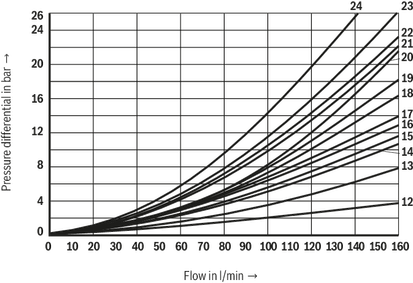
(measured with HLP46, ϑOil = 40 ±5 °C)
Notice:
The specified performance limits are valid for use with two directions of flow (e. g. from P to A and simultaneous return flow from B to T).
Due to the flow forces acting within the valves, the admissible performance limit may be considerably lower with only one direction of flow (e. g. from P to A while port B is blocked)!
In such use cases, please consult us!
The performance limit was determined when the solenoids were at operating temperature, at 10 % undervoltage and without tank preloading.
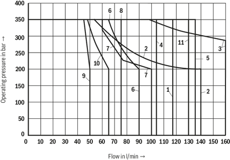
Characteristic curve | Symbol |
1 | L |
2 | A |
3 | B |
4 | Y |
5 | E73, Q |
6 | F |
7 | G73 |
8 | M; V |
9 | P |
10 | A73 |
11 | H73 |
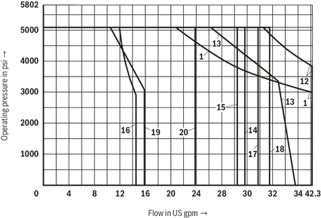
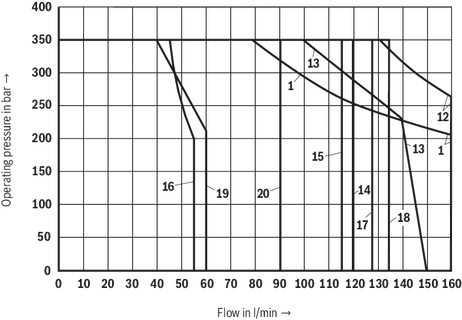
Characteristic curve | Symbol |
1 | L |
12 | A/O |
13 | J |
14 | H |
15 | D73 |
16 | B73 |
17 | Y11 |
18 | C; D; E73 |
19 | E67 |
20 | G |
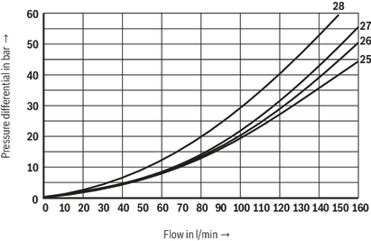
(measured with HLP46, ϑOil = 40 ±5 °C)
Notice:
The specified performance limits are valid for use with two directions of flow (e. g. from P to A and simultaneous return flow from B to T).
Due to the flow forces acting within the valves, the admissible performance limit may be considerably lower with only one direction of flow (e. g. from P to A while port B is blocked)!
In such use cases, please consult us!
The performance limit was determined when the solenoids were at operating temperature, at 10 % undervoltage and without tank preloading.
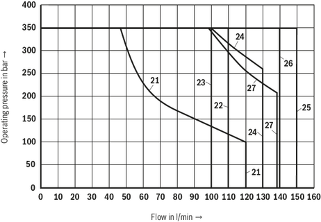
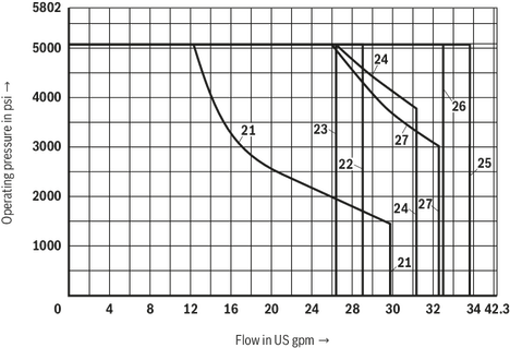
Characteristic curve | Symbol |
21 | A; B |
22 | G73 |
23 | F; L73 |
24 | E |
25 | C/O; D/O |
26 | J73 |
27 | U |
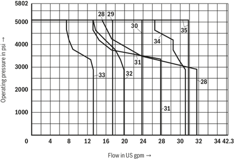
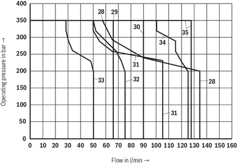
Characteristic curve | Symbol |
28 | Q |
29 | V |
30 | P |
31 | R |
32 | R73 |
33 | T |
34 | U73 |
35 | Y73 |
Symbol | Direction of flow | |||
P –A | P – B | A – T | B – T | |
A; B | 6 | 6 | – | – |
A73, B73 | 23 | 23 | – | – |
C | 1 | 2 | 5 | 7 |
D | 2 | 2 | 5 | 7 |
D73 | 25 | 26 | 26 | 27 |
E | 17 | 16 | 19 | 21 |
E67 | 4 | 4 | 11 | 24 |
E73 | 17 | 18 | 21 | 21 |
F | 2 | 3 | 22 | 23 |
G | 4 | 4 | 24 | 24 |
G73 | 18 | 18 | 24 | 24 |
H | 14 | 14 | 20 | 21 |
H73 | 14 | 14 | 6 | 9 |
J | 3 | 3 | 9 | 11 |
J73 | 22 | 21 | 23 | 24 |
L | 3 | 3 | 9 | 9 |
L73 | 22 | 10 | 11 | 24 |
M | 14 | 14 | 6 | 8 |
P | 17 | 14 | 20 | 23 |
Q | 16 | 17 | 4 | 8 |
R | 18 | 21 | 18 | 24 |
R73 | 24 | 24 | 23 | 24 |
T | 18 | 4 | 10 | 24 |
U | 3 | 3 | 6 | 11 |
U10 | upon request | |||
U73 | 22 | 22 | 23 | 24 |
V | 17 | 17 | 18 | 20 |
W | upon request | |||
X7 | upon request | |||
X34 | upon request | |||
Y | 17 | 16 | 18 | 21 |
Y11 | 3 | 2 | 4 | 9 |
Y73 | 26 | 26 | 26 | 28 |
Central position: | |||||
Symbol | Direction of flow | ||||
P – A | P – B | B – T | A – T | P – T | |
H | 12 | 12 | 13 | 13 | 15 |
(measured with HLP46, ϑOil = 40 ±5 °C)
Notice:
The specified performance limits are valid for use with two directions of flow (e. g. from P to A and simultaneous return flow from B to T).
Due to the flow forces acting within the valves, the admissible performance limit may be considerably lower with only one direction of flow (e. g. from P to A while port B is blocked)!
In such use cases, please consult us!
The performance limit was determined when the solenoids were at operating temperature, at 10 % undervoltage and without tank preloading.
Characteristic curve | Symbol |
1 | L |
2 | A |
3 | B |
4 | Y |
5 | E73, Q |
6 | F |
7 | G73 |
8 | M; V |
9 | P |
10 | A73 |
11 | H73 |
Characteristic curve | Symbol |
1 | L |
12 | A/O |
13 | J |
14 | H |
15 | D73 |
16 | B73 |
17 | Y11 |
18 | C; D; E73 |
19 | E67 |
20 | G |
(measured with HLP46, ϑOil = 40 ±5 °C)
Notice:
The specified performance limits are valid for use with two directions of flow (e. g. from P to A and simultaneous return flow from B to T).
Due to the flow forces acting within the valves, the admissible performance limit may be considerably lower with only one direction of flow (e. g. from P to A while port B is blocked)!
In such use cases, please consult us!
The performance limit was determined when the solenoids were at operating temperature, at 10 % undervoltage and without tank preloading.
Characteristic curve | Symbol |
21 | A; B |
22 | G73 |
23 | F; L73 |
24 | E |
25 | C/O; D/O |
26 | J73 |
27 | U |
Characteristic curve | Symbol |
28 | Q |
29 | V |
30 | P |
31 | R |
32 | R73 |
33 | T |
34 | U73 |
35 | Y73 |


