| Availability: | |
|---|---|
| Quantity: | |

SL10PA1-4X
Rexroth
R983040145
For subplate mounting
Porting pattern according to ISO 5781-06-07-0-00 (NG10), ISO 5781-08-10-0-00 (NG20), ISO 5781-10-13-0-00 (NG32)
For threaded connection
For the leakage-free blocking of one actuator port
Attachment possibility for directional spool valve or directional seat valve, optional
Pilot oil return, external
Version with pre-opening for dampened release, optional
Various cracking pressures, optional
Check valve installation sets available individually
Corrosion-protected design
The isolator valve type SL is a releasable check valve for subplate mounting or threaded connection. It is used for the leakage-free blocking of one actuator port, also in case of longer standstill times.
The valve basically consists of a housing (1), a seat poppet (2), a compression spring (3), a control spool (4) as well as of an optional pre-opening as ball seat valve (5).
The seat valve can be flown through from A to B without external pilot pressure. In the opposite direction, the seat valve closes hydraulically tight.
Condition: pA > pB + cracking pressure (compression spring).
A sufficiently high pilot pressure at port X moves the control spool (4) in the direction of the ball seat valve (5) (version "A") and pushes the seat poppet (2) out of its seat. This allows for a free flow in both directions (active keeping open).
In order to ensure that the seat valve actively opens, the pressure ratios on both sides of the control spool (4) are just as important as the area ratios at the control spool (4) or seat poppet (2).
This results in the versions with pre-opening "A" and without pre-opening "B” for type SL (small annulus area). A4 (9).
Version "A" (with pre-opening)
This valve is provided with an additional pre-opening. By pressurization at the X port, the control spool (4) is moved to the right. As a result, the ball (5) is pushed off the seat first and the seat poppet (2) afterwards.
Notes:
Version "A”:
The two-stage set-up with an increased control open ratio means even low pilot pressure can be unloaded securely.
Avoidance of switching shocks due to dampened decompression of the pressure volume on the actuator side.
Version "B”:
In case of valves without pre-opening, the included pressure volume may be unloaded suddenly. Resulting switching shocks may lead to premature wear on installed components, as well as noise formation.
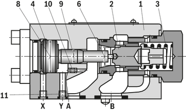
6 | Area A1 (seat poppet) |
7 | Area A2 (ball) |
8 | AreaA 3 (control spool) |
9 | Area A4 (control spool) |
Notice:
The modification of type SV to type SL is possible by exchange of plugs (10) and (11). One of the both plugs must always be installed.
NG | Plug (10) | Plug (11) |
10 | M3 | M6 |
20 | M4 | M6 |
30 | M4 | M6 |
At direct operated, pilot operated check valves type SL with built-on directional valve, the control spool (4) may be controlled directly via the directional valve to open the seat poppet (2) against the system pressure, i.e. the blocking direction.
Notice:
When ordering the directional valve, please observe the different position of port A at versions "P" and "G" (porting pattern rotated by 180° at version "G", see "Dimensions").
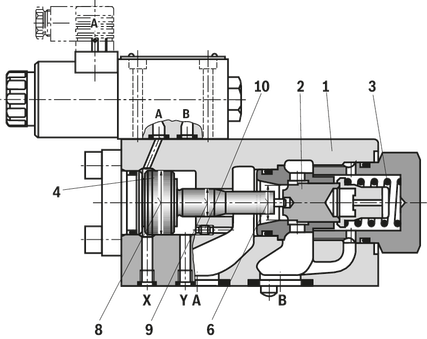
6 | Area A1 (seat poppet) |
8 | AreaA 3 (control spool) |
9 | Area A4 (control spool) |
The isolator valve type SL is a releasable check valve for subplate mounting or threaded connection. It is used for the leakage-free blocking of one actuator port, also in case of longer standstill times.
The valve basically consists of a housing (1), a seat poppet (2), a compression spring (3), a control spool (4) as well as of an optional pre-opening as ball seat valve (5).
The seat valve can be flown through from A to B without external pilot pressure. In the opposite direction, the seat valve closes hydraulically tight.
Condition: pA > pB + cracking pressure (compression spring).
A sufficiently high pilot pressure at port X moves the control spool (4) in the direction of the ball seat valve (5) (version "A") and pushes the seat poppet (2) out of its seat. This allows for a free flow in both directions (active keeping open).
In order to ensure that the seat valve actively opens, the pressure ratios on both sides of the control spool (4) are just as important as the area ratios at the control spool (4) or seat poppet (2).
This results in the versions with pre-opening "A" and without pre-opening "B” for type SL (small annulus area). A4 (9).
Version "A" (with pre-opening)
This valve is provided with an additional pre-opening. By pressurization at the X port, the control spool (4) is moved to the right. As a result, the ball (5) is pushed off the seat first and the seat poppet (2) afterwards.
Notes:
Version "A”:
The two-stage set-up with an increased control open ratio means even low pilot pressure can be unloaded securely.
Avoidance of switching shocks due to dampened decompression of the pressure volume on the actuator side.
Version "B”:
In case of valves without pre-opening, the included pressure volume may be unloaded suddenly. Resulting switching shocks may lead to premature wear on installed components, as well as noise formation.
6 | Area A1 (seat poppet) |
7 | Area A2 (ball) |
8 | AreaA 3 (control spool) |
9 | Area A4 (control spool) |
Notice:
The modification of type SV to type SL is possible by exchange of plugs (10) and (11). One of the both plugs must always be installed.
NG | Plug (10) | Plug (11) |
10 | M3 | M6 |
20 | M4 | M6 |
30 | M4 | M6 |
At direct operated, pilot operated check valves type SL with built-on directional valve, the control spool (4) may be controlled directly via the directional valve to open the seat poppet (2) against the system pressure, i.e. the blocking direction.
Notice:
When ordering the directional valve, please observe the different position of port A at versions "P" and "G" (porting pattern rotated by 180° at version "G", see "Dimensions").
6 | Area A1 (seat poppet) |
8 | AreaA 3 (control spool) |
9 | Area A4 (control spool) |
01 | 02 | 03 | 04 | 05 | 06 | 07 | 08 | 09 | 10 | 11 | 12 | 13 | 14 | 15 | 16 | 17 | 18 | 19 | 20 | |||
S | L | – | 4X | / | – | * |
01 | Check valve | S |
02 | Pilot oil return, external | L |
03 | Size 10 | 10 |
Size 20 | 20 | |
Size 32 | 30 | |
Type of connection | ||
04 | Subplate mounting | P |
Threaded connection | G | |
05 | With pre-opening | A |
Without pre-opening | B | |
Cracking pressure | ||
06 | See characteristic curves (A → B) | 1 |
2 | ||
3 | ||
4 | ||
07 | Component series 40 … 49 (40 … 49: unchanged installation and mounting dimensions) | 4X |
08 | Without attachment possibility for directional spool or seat valve | no code |
With attachment possibility for directional spool or seat valve (NG6) | 6U 1) | |
Spool position monitoring | ||
09 | Without position switch | no code |
With position switch 2) | QMG24 | |
For more information see "Electrical connection" | ||
Orifice fitting channel A (version "6U" only) | ||
10 | Orifice Ø0,8 mm in channel A (standard) | A08 |
Orifice Ø** in channel A 3) | A** | |
Orifice fitting channel B (version "6U" only) | ||
11 | Channel B closed (standard) | B99 |
Orifice Ø** in channel B 3) | B** | |
Orifice fitting channel T (version "6U" only) | ||
12 | Without orifice (standard) | T00 |
Orifice Ø** in channel T 3) | T** | |
Orifice fitting channel P (version "6U" only) | ||
13 | Without orifice (standard) | P00 |
Orifice Ø** in channel P 3) | P** | |
Orifice fitting channel X (version "6U" only) | ||
14 | Channel X closed (standard) | X99 |
Orifice Ø** in channel X 3) | X** | |
Orifice fitting channel Y | ||
15 | Channel Y open (standard) | Y00 |
Orifice Ø** in channel Y 3) | Y** | |
Seal material | ||
16 | NBR seals | N |
FKM seals | V | |
Observe compatibility of seals with hydraulic fluid used. (Other seals upon request) | ||
Corrosion resistance | ||
17 | None | no code |
Improved corrosion protection (240 h salt spray test according to EN ISO 9227) | J3 | |
18 | Standard | no code |
Pilot pressure ppilot from channel X | SO168 | |
Control open spool with shaft sealing (between channel X–Y and Y–A) | SO286 | |
Connection thread (versions with threaded connection "G" only) | ||
19 | Pipe thread "G" according to ISO 228-1 | no code |
Pipe thread “UNF/UN” according to ANSI/ASME B 1.1 | /12 | |
20 | Further details in the plain text | * |
| 1) | Only size 20 and 32 |
| 2) | Only version "B3" |
| 3) | Order example: ** = dimension in mm x 10 – e.g. orifice Ø1,2 mm in channel Y = "Y12" |
Size | 10 | 20 | 32 | ||
Weight | Subplate mounting | kg | 1.8 | 4.7 | 7.8 |
Threaded connection | kg | 2.1 | 5.4 | 10 | |
Installation position | any | ||||
Ambient temperature range | NBR seals | °C | -30 … +80 | ||
FKM seals | °C | -20 … +80 | |||
MTTFD values according to EN ISO 13849 1) | Years | 150 | |||
Maximum storage time 2) | Months | 12 | |||
| 1) | For further details, see data sheet 08012 |
| 2) | If the storage conditions are observed; refer to the operating instructions 07600-B |
Size | 10 | 20 | 32 | ||
Maximum operating pressure | bar | 315 | |||
Cracking pressure | bar | 1.5 / 3 / 6 / 10 | 2.5 / 5 / 7.5 / 10 | 2.5 / 5 / 8 / 10 | |
Minimum pilot pressure | bar | 5 | |||
Maximum pilot pressure | bar | 315 | |||
Maximum flow | See characteristic curves | ||||
Direction of flow | Free from A → B, from B → A by opening | ||||
Hydraulic fluid | see table below | ||||
Hydraulic fluid temperature range | NBR seals | °C | -30 … +80 | ||
FPM seals | °C | -20 … +80 | |||
Viscosity range | mm²/s | 2.8 … 500 | |||
Maximum admissible degree of contamination of the hydraulic fluid, cleanliness class according to ISO 4406 (c) 1) | Class 20/18/15 | ||||
Pilot volume | Port X | cm³ | 2.5 | 10.8 | 19.27 |
Port Y | cm³ | 2 | 9.6 | 17.5 | |
Control area A1 2) | cm² | 1.33 | 3.46 | 5.72 | |
Control area A2 2) | cm² | 0.33 | 0.7 | 1.33 | |
Control area A3 2) | cm² | 3.8 | 10.17 | 16.61 | |
Control area A4 2) | cm² | 0.79 | 1.13 | 1.54 | |
| 1) | The cleanliness classes specified for the components must be adhered to in hydraulic systems. Effective filtration prevents faults and simultaneously increases the life cycle of the components. For the selection of the filters, see www.boschrexroth.com/filter. |
| 2) | Areas according to sectional drawing, see "Product description" |
Hydraulic fluid | Classification | Suitable sealing materials | Standards | Data sheet | |
Mineral oils | HL, HLP, HLPD, HVLP, HVLPD | NBR, FKM | DIN 51524 | 90220 | |
Bio-degradable | Insoluble in water | HETG 1) | NBR, FKM | ISO 15380 | 90221 |
HEES 1) | FKM | ||||
Soluble in water | HEPG 1) | FKM | ISO 15380 | ||
Flame-resistant | Water-free | HFDU (glycol base) | FKM | ISO 12922 | 90222 |
HFDU (ester base) 1) | FKM | ||||
HFDR | FKM | ||||
Containing water | HFC (Fuchs Hydrotherm 46M, Petrofer Ultra Safe 620) 1) | NBR | ISO 12922 | 90223 | |
Important information on hydraulic fluids:
| |||||
| 1) | Not recommended for corrosion-protected version "J3" (contains zinc) |
Size | 10 | 20 | 32 | ||
Weight | Subplate mounting | kg | 1.8 | 4.7 | 7.8 |
Threaded connection | kg | 2.1 | 5.4 | 10 | |
Installation position | any | ||||
Ambient temperature range | NBR seals | °C | -30 … +80 | ||
FKM seals | °C | -20 … +80 | |||
MTTFD values according to EN ISO 13849 1) | Years | 150 | |||
Maximum storage time 2) | Months | 12 | |||
| 1) | For further details, see data sheet 08012 |
| 2) | If the storage conditions are observed; refer to the operating instructions 07600-B |
Size | 10 | 20 | 32 | ||
Maximum operating pressure | bar | 315 | |||
Cracking pressure | bar | 1.5 / 3 / 6 / 10 | 2.5 / 5 / 7.5 / 10 | 2.5 / 5 / 8 / 10 | |
Minimum pilot pressure | bar | 5 | |||
Maximum pilot pressure | bar | 315 | |||
Maximum flow | See characteristic curves | ||||
Direction of flow | Free from A → B, from B → A by opening | ||||
Hydraulic fluid | see table below | ||||
Hydraulic fluid temperature range | NBR seals | °C | -30 … +80 | ||
FPM seals | °C | -20 … +80 | |||
Viscosity range | mm²/s | 2.8 … 500 | |||
Maximum admissible degree of contamination of the hydraulic fluid, cleanliness class according to ISO 4406 (c) 1) | Class 20/18/15 | ||||
Pilot volume | Port X | cm³ | 2.5 | 10.8 | 19.27 |
Port Y | cm³ | 2 | 9.6 | 17.5 | |
Control area A1 2) | cm² | 1.33 | 3.46 | 5.72 | |
Control area A2 2) | cm² | 0.33 | 0.7 | 1.33 | |
Control area A3 2) | cm² | 3.8 | 10.17 | 16.61 | |
Control area A4 2) | cm² | 0.79 | 1.13 | 1.54 | |
| 1) | The cleanliness classes specified for the components must be adhered to in hydraulic systems. Effective filtration prevents faults and simultaneously increases the life cycle of the components. For the selection of the filters, see www.boschrexroth.com/filter. |
| 2) | Areas according to sectional drawing, see "Product description" |
Hydraulic fluid | Classification | Suitable sealing materials | Standards | Data sheet | |
Mineral oils | HL, HLP, HLPD, HVLP, HVLPD | NBR, FKM | DIN 51524 | 90220 | |
Bio-degradable | Insoluble in water | HETG 1) | NBR, FKM | ISO 15380 | 90221 |
HEES 1) | FKM | ||||
Soluble in water | HEPG 1) | FKM | ISO 15380 | ||
Flame-resistant | Water-free | HFDU (glycol base) | FKM | ISO 12922 | 90222 |
HFDU (ester base) 1) | FKM | ||||
HFDR | FKM | ||||
Containing water | HFC (Fuchs Hydrotherm 46M, Petrofer Ultra Safe 620) 1) | NBR | ISO 12922 | 90223 | |
Important information on hydraulic fluids:
| |||||
| 1) | Not recommended for corrosion-protected version "J3" (contains zinc) |

 |
Required surface quality of the valve contact surface |
1 | Port Y open |
2 | Name plate |
3 | Locking pin |
4 | Identical seal rings for ports A and B |
5 | Valve with cracking pressure Version "1" and "2" (dimension L2) |
6 | Valve with cracking pressure version "3" and "4" (dimension L3) |
7.1 | 6 valve mounting bores at NG32 |
8 | Porting pattern according to ISO 5781 |
9 | Version without position switch |
10 | Version with position switch "QMG24" (circuitry see "Electrical connection") |
NG | L1 | L2 | L3 | L4 | L5 | L6 | L7 | L8 | L9 | L10 | L11 | L12 | L13 | L14 | B1 | B2 | B3 | B4 | B5 | B6 | H1 | H2 | H3 |
mm | mm | mm | mm | mm | mm | mm | mm | mm | mm | mm | mm | mm | mm | mm | mm | mm | mm | mm | mm | mm | mm | mm | |
| 10 | 100.8 | 15.5 | 15.5 | 87.8 | 13 | 42.9 | 18.5 | 7.2 | 35.8 | 21.5 | 21.5 | - | 31.8 | 105 | 84 | 66.7 | 44 | 58.8 | 7.9 | 33.3 | 51 | 29 | 36 |
| 20 | 135 | 17.7 | 47.7 | 117 | 18 | 60.3 | 27.5 | 11.1 | 49.2 | 39.5 | 20.6 | - | 44.5 | 96.5 | 100 | 79.4 | 67 | 73 | 6.4 | 39.7 | 81 | 45 | 55 |
| 32 | 156.1 | 36.1 | 46.1 | 134 | 22.1 | 84.2 | 39 | 16.7 | 67.5 | 59.5 | 24.6 | 42.1 | 62.7 | 117 | 118 | 96.8 | 75 | 92.8 | 3.8 | 48.4 | 85 | 42.5 | 70 |
Size | Quantity | Hexagon socket head cap screws | Material number |
10 | 4 | ISO 4762 - M10 x 50 - 10.9 Tightening torque MA = 75 Nm ±20 % | - |
20 | 4 | ISO 4762 - M10 x 70 - 10.9 Tightening torque MA = 75 Nm ±20 % | - |
32 | 6 | ISO 4762 - M10 x 85 - 10.9 Tightening torque MA = 75 Nm ±20 % | - |
Notice:
The specified tightening torques were calculated with total friction coefficient μtotal = 0.09 ... 0.14; adjust in case of modified surfaces.
Subplates (separate order)
with porting pattern according to ISO 5781-06-07-0-00 (NG10), ISO 5781-08-10-0-00 (NG20), ISO 5781-10-13-0-00 (NG32) see data sheet 45100.

1 | Port Y open |
2 | Name plate |
5 | Valve with cracking pressure Version "1" and "2" (dimension L2) |
6 | Valve with cracking pressure version "3" and "4" (dimension L3) |
7.2 | 2 valve mounting bores |
9 | Version without position switch |
10 | Version with position switch "QMG24" (circuitry see "Electrical connection") |
Ports
NG | A | B | X | Y |
"G" | "UNF/UN" | "G" | "UNF/UN" | |
| 10 | G1/2 | 3/4-16 UNF | G1/4 | 7/16-20 UN |
| 20 | G1 | 1 5/16-12 UN | G1/4 | 7/16-20 UN |
| 32 | G1 1/2 | 1 7/8-12 UN | G1/4 | 7/16-20 UN |
Size | Quantity | Hexagon socket head cap screws | Material number |
10 | 2 | ISO 4762 - M10 x 60 - 10.9 | - |
20 | 2 | ISO 4762 - M10 x 85 - 10.9 | - |
32 | 2 | ISO 4762 - M10 x 100 - 10.9 | - |
Dimensions in mm
| |
Required surface quality of the valve contact surface |
1 | Port Y open |
2 | Name plate |
3 | Locking pin |
4 | Identical seal rings for ports A and B |
5 | Valve with cracking pressure Version "1" and "2" (dimension L2) |
6 | Valve with cracking pressure version "3" and "4" (dimension L3) |
7.1 | 6 valve mounting bores at NG32 |
8 | Porting pattern according to ISO 5781 |
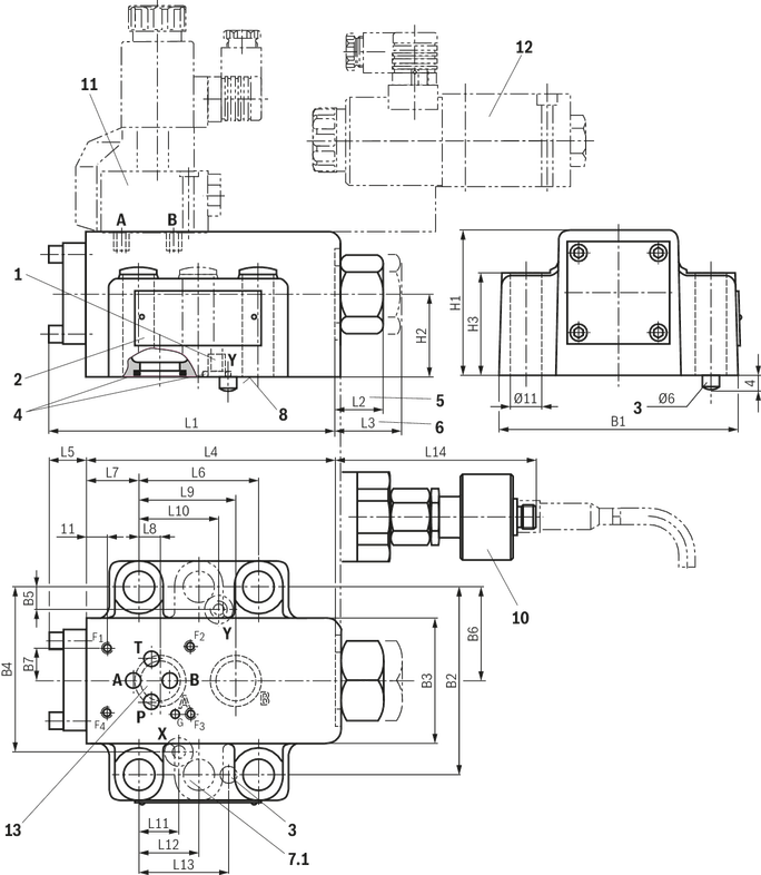
10 | Version with position switch "QMG24" (circuitry see "Electrical connection") |
11 | Directional seat valve type M-3SEW 6 ... (data sheet 22058) |
12 | Directional spool valve type 4WE 6 ... (data sheet 23178) |
13 | Porting pattern according to ISO 4401-03-02-0-05 |
NG | L1 | L2 | L3 | L4 | L5 | L6 | L7 | L8 | L9 | L10 | L11 | L12 | L13 | L14 | B1 | B2 | B3 | B4 | B5 | B6 | B7 | H1 | H2 | H3 |
mm | mm | mm | mm | mm | mm | mm | mm | mm | mm | mm | mm | mm | mm | mm | mm | mm | mm | mm | mm | mm | mm | mm | mm | |
| 20 | 135 | 17.7 | 47.7 | 117 | 18 | 60.3 | 27.5 | 11.1 | 49.2 | 39.7 | 20.6 | - | 44.5 | 96.5 | 100 | 79.4 | 61 | 73 | 6.4 | 39.7 | 11 | 81 | 45 | 55 |
| 32 | 156.1 | 36.1 | 46.1 | 134 | 22.1 | 84.2 | 39 | 16.7 | 67.5 | - | 24.6 | 42.1 | 62.7 | 117 | 118 | 96.8 | 75 | 92.8 | - | 48.4 | 11 | 85 | 42.5 | 70 |
Size | Quantity | Hexagon socket head cap screws | Material number |
10 | 4 | ISO 4762 - M10 x 50 - 10.9 Tightening torque MA = 75 Nm ±20 % | - |
20 | 4 | ISO 4762 - M10 x 70 - 10.9 Tightening torque MA = 75 Nm ±20 % | - |
32 | 6 | ISO 4762 - M10 x 85 - 10.9 Tightening torque MA = 75 Nm ±20 % | - |
Notice:
The specified tightening torques were calculated with total friction coefficient μtotal = 0.09 ... 0.14; adjust in case of modified surfaces.
Subplates (separate order)
with porting pattern according to ISO 5781-06-07-0-00 (NG10), ISO 5781-08-10-0-00 (NG20), ISO 5781-10-13-0-00 (NG32) see data sheet 45100.
Dimensions in mm

1 | Port Y open |
2 | Name plate |
5 | Valve with cracking pressure Version "1" and "2" (dimension L2) |
6 | Valve with cracking pressure version "3" and "4" (dimension L3) |
7.1 | 6 valve mounting bores at NG32 |
7.2 | 2 valve mounting bores |
10 | Version with position switch "QMG24" (circuitry see "Electrical connection") |
11 | Directional seat valve type M-3SEW 6 ... (data sheet 22058) |
12 | Directional spool valve type 4WE 6 ... (data sheet 23178) |
13 | Porting pattern according to ISO 4401-03-02-0-05 |
NG | L1 | L2 | L3 | L4 | L5 | L6 | L7 | L8 | L9 | L10 | L11 | L12 | B1 | B2 | B3 | B4 | H1 | H2 |
mm | mm | mm | mm | mm | mm | mm | mm | mm | mm | mm | mm | mm | mm | mm | mm | mm | mm | |
| 20 | 133 | 17.7 | 47.7 | 115 | 18 | 74.5 | 17 | 50.5 | 36 | 27 | 53 | 96.5 | 105 | 79.4 | 39.7 | 8.25 | 68 | 34 |
| 32 | 156.1 | 35.7 | 45.7 | 134 | 22.1 | 101 | 24 | 84 | 49 | 18 | 59 | 117 | 130 | 96.8 | 48.4 | 3.25 | 85 | 42.5 |
Ports
NG | A | B | X | Y |
"G" | "UNF/UN" | "G" | "UNF/UN" | |
| 20 | G1 | 1 5/16-12 UN | G1/4 | 7/16-20 UN |
| 32 | G1 1/2 | 1 7/8-12 UN | G1/4 | 7/16-20 UN |
Size | Quantity | Hexagon socket head cap screws | Material number |
10 | 2 | ISO 4762 - M10 x 60 - 10.9 | - |
20 | 2 | ISO 4762 - M10 x 85 - 10.9 | - |
32 | 2 | ISO 4762 - M10 x 100 - 10.9 | - |
Material number | Male thread | Internal thread | Seal (separate order) | |
NBR | FKM | |||
R900173685 | G1 | G3/4 | R900012475 | R900012509 |
R900173689 | G1 1/2 | G1 1/4 | R900012477 | R900012511 |
| |
Required surface quality of the valve contact surface |
1 | Port Y open |
2 | Name plate |
3 | Locking pin |
4 | Identical seal rings for ports A and B |
5 | Valve with cracking pressure Version "1" and "2" (dimension L2) |
6 | Valve with cracking pressure version "3" and "4" (dimension L3) |
7.1 | 6 valve mounting bores at NG32 |
8 | Porting pattern according to ISO 5781 |
9 | Version without position switch |
10 | Version with position switch "QMG24" (circuitry see "Electrical connection") |
NG | L1 | L2 | L3 | L4 | L5 | L6 | L7 | L8 | L9 | L10 | L11 | L12 | L13 | L14 | B1 | B2 | B3 | B4 | B5 | B6 | H1 | H2 | H3 |
mm | mm | mm | mm | mm | mm | mm | mm | mm | mm | mm | mm | mm | mm | mm | mm | mm | mm | mm | mm | mm | mm | mm | |
| 10 | 100.8 | 15.5 | 15.5 | 87.8 | 13 | 42.9 | 18.5 | 7.2 | 35.8 | 21.5 | 21.5 | - | 31.8 | 105 | 84 | 66.7 | 44 | 58.8 | 7.9 | 33.3 | 51 | 29 | 36 |
| 20 | 135 | 17.7 | 47.7 | 117 | 18 | 60.3 | 27.5 | 11.1 | 49.2 | 39.5 | 20.6 | - | 44.5 | 96.5 | 100 | 79.4 | 67 | 73 | 6.4 | 39.7 | 81 | 45 | 55 |
| 32 | 156.1 | 36.1 | 46.1 | 134 | 22.1 | 84.2 | 39 | 16.7 | 67.5 | 59.5 | 24.6 | 42.1 | 62.7 | 117 | 118 | 96.8 | 75 | 92.8 | 3.8 | 48.4 | 85 | 42.5 | 70 |
Size | Quantity | Hexagon socket head cap screws | Material number |
10 | 4 | ISO 4762 - M10 x 50 - 10.9 Tightening torque MA = 75 Nm ±20 % | - |
20 | 4 | ISO 4762 - M10 x 70 - 10.9 Tightening torque MA = 75 Nm ±20 % | - |
32 | 6 | ISO 4762 - M10 x 85 - 10.9 Tightening torque MA = 75 Nm ±20 % | - |
Notice:
The specified tightening torques were calculated with total friction coefficient μtotal = 0.09 ... 0.14; adjust in case of modified surfaces.
Subplates (separate order)
with porting pattern according to ISO 5781-06-07-0-00 (NG10), ISO 5781-08-10-0-00 (NG20), ISO 5781-10-13-0-00 (NG32) see data sheet 45100.
1 | Port Y open |
2 | Name plate |
5 | Valve with cracking pressure Version "1" and "2" (dimension L2) |
6 | Valve with cracking pressure version "3" and "4" (dimension L3) |
7.2 | 2 valve mounting bores |
9 | Version without position switch |
10 | Version with position switch "QMG24" (circuitry see "Electrical connection") |
Ports
NG | A | B | X | Y |
"G" | "UNF/UN" | "G" | "UNF/UN" | |
| 10 | G1/2 | 3/4-16 UNF | G1/4 | 7/16-20 UN |
| 20 | G1 | 1 5/16-12 UN | G1/4 | 7/16-20 UN |
| 32 | G1 1/2 | 1 7/8-12 UN | G1/4 | 7/16-20 UN |
Size | Quantity | Hexagon socket head cap screws | Material number |
10 | 2 | ISO 4762 - M10 x 60 - 10.9 | - |
20 | 2 | ISO 4762 - M10 x 85 - 10.9 | - |
32 | 2 | ISO 4762 - M10 x 100 - 10.9 | - |
Dimensions in mm
| |
Required surface quality of the valve contact surface |
1 | Port Y open |
2 | Name plate |
3 | Locking pin |
4 | Identical seal rings for ports A and B |
5 | Valve with cracking pressure Version "1" and "2" (dimension L2) |
6 | Valve with cracking pressure version "3" and "4" (dimension L3) |
7.1 | 6 valve mounting bores at NG32 |
8 | Porting pattern according to ISO 5781 |
10 | Version with position switch "QMG24" (circuitry see "Electrical connection") |
11 | Directional seat valve type M-3SEW 6 ... (data sheet 22058) |
12 | Directional spool valve type 4WE 6 ... (data sheet 23178) |
13 | Porting pattern according to ISO 4401-03-02-0-05 |
NG | L1 | L2 | L3 | L4 | L5 | L6 | L7 | L8 | L9 | L10 | L11 | L12 | L13 | L14 | B1 | B2 | B3 | B4 | B5 | B6 | B7 | H1 | H2 | H3 |
mm | mm | mm | mm | mm | mm | mm | mm | mm | mm | mm | mm | mm | mm | mm | mm | mm | mm | mm | mm | mm | mm | mm | mm | |
| 20 | 135 | 17.7 | 47.7 | 117 | 18 | 60.3 | 27.5 | 11.1 | 49.2 | 39.7 | 20.6 | - | 44.5 | 96.5 | 100 | 79.4 | 61 | 73 | 6.4 | 39.7 | 11 | 81 | 45 | 55 |
| 32 | 156.1 | 36.1 | 46.1 | 134 | 22.1 | 84.2 | 39 | 16.7 | 67.5 | - | 24.6 | 42.1 | 62.7 | 117 | 118 | 96.8 | 75 | 92.8 | - | 48.4 | 11 | 85 | 42.5 | 70 |
Size | Quantity | Hexagon socket head cap screws | Material number |
10 | 4 | ISO 4762 - M10 x 50 - 10.9 Tightening torque MA = 75 Nm ±20 % | - |
20 | 4 | ISO 4762 - M10 x 70 - 10.9 Tightening torque MA = 75 Nm ±20 % | - |
32 | 6 | ISO 4762 - M10 x 85 - 10.9 Tightening torque MA = 75 Nm ±20 % | - |
Notice:
The specified tightening torques were calculated with total friction coefficient μtotal = 0.09 ... 0.14; adjust in case of modified surfaces.
Subplates (separate order)
with porting pattern according to ISO 5781-06-07-0-00 (NG10), ISO 5781-08-10-0-00 (NG20), ISO 5781-10-13-0-00 (NG32) see data sheet 45100.
Dimensions in mm
1 | Port Y open |
2 | Name plate |
5 | Valve with cracking pressure Version "1" and "2" (dimension L2) |
6 | Valve with cracking pressure version "3" and "4" (dimension L3) |
7.1 | 6 valve mounting bores at NG32 |
7.2 | 2 valve mounting bores |
10 | Version with position switch "QMG24" (circuitry see "Electrical connection") |
11 | Directional seat valve type M-3SEW 6 ... (data sheet 22058) |
12 | Directional spool valve type 4WE 6 ... (data sheet 23178) |
13 | Porting pattern according to ISO 4401-03-02-0-05 |
NG | L1 | L2 | L3 | L4 | L5 | L6 | L7 | L8 | L9 | L10 | L11 | L12 | B1 | B2 | B3 | B4 | H1 | H2 |
mm | mm | mm | mm | mm | mm | mm | mm | mm | mm | mm | mm | mm | mm | mm | mm | mm | mm | |
| 20 | 133 | 17.7 | 47.7 | 115 | 18 | 74.5 | 17 | 50.5 | 36 | 27 | 53 | 96.5 | 105 | 79.4 | 39.7 | 8.25 | 68 | 34 |
| 32 | 156.1 | 35.7 | 45.7 | 134 | 22.1 | 101 | 24 | 84 | 49 | 18 | 59 | 117 | 130 | 96.8 | 48.4 | 3.25 | 85 | 42.5 |
Ports
NG | A | B | X | Y |
"G" | "UNF/UN" | "G" | "UNF/UN" | |
| 20 | G1 | 1 5/16-12 UN | G1/4 | 7/16-20 UN |
| 32 | G1 1/2 | 1 7/8-12 UN | G1/4 | 7/16-20 UN |
Size | Quantity | Hexagon socket head cap screws | Material number |
10 | 2 | ISO 4762 - M10 x 60 - 10.9 | - |
20 | 2 | ISO 4762 - M10 x 85 - 10.9 | - |
32 | 2 | ISO 4762 - M10 x 100 - 10.9 | - |
Material number | Male thread | Internal thread | Seal (separate order) | |
NBR | FKM | |||
R900173685 | G1 | G3/4 | R900012475 | R900012509 |
R900173689 | G1 1/2 | G1 1/4 | R900012477 | R900012511 |


