| Availability: | |
|---|---|
| Quantity: | |

DZ 20-1-5X/200YM
Rexroth
R900599115
Suitable for use as preload, sequencing and changeover valve
For subplate mounting
Porting pattern according to ISO 5781
As cartridge valve
4 pressure ratings
4 adjustment types:
• Rotary knob
• Sleeve with hexagon and protective cap
• Lockable rotary knob with scale
• Rotary knob with scale
Check valve, optional
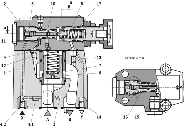
The valve type DZ is a pilot-operated pressure sequence valve.
It is applied for pressure-dependent connection of a second system.
The pressure sequence valve basically consists of main valve (1) with main spool insert (7) and pilot control valve (2) with adjustment type and optional check valve (3).
According to the pilot oil supply and return and the respective function, the following differentiation is made:
Preload valve type DZ. . -.-5X/… (control lines 4.1, 12 and 13 open; control lines 4.2, 14 and 15 closed)
The pressure applied in channel A acts via the control line (4.1) on the pilot spool (5) in the pilot control valve (2). Simultaneously, the pressure in channel A acts via the nozzle (6) on the spring-loaded side of the main spool (7). If the pressure in channel P exceeds the value set at the spring (8), the pilot spool (5) is moved against the spring (8). The hydraulic fluid on the spring-loaded side of the main spool (7) now flows via the nozzle (9), the control edge (10) and control lines (11) and (12) into channel B. Due to this, a pressure drop occurs at the main spool (7). The main spool (7) is moved upwards and opens the connections from channel A to B. The pressure in channel A exceeds the value in channel B by the value set at the spring (8). The leakage occurring at the pilot spool (5) is directed internally via the spring chamber (17) of the pilot control valve and the control line (13) into channel B. If the pressure in the secondary circuit (channel B) exceeds the pressure in channel A, a check valve (3) may be optionally installed for free return flow.
Preload valve type DZ. . -.-5X/.X… (control lines 4.2, 12 and 13 open; control lines 4.1, 14 and 15 closed)
In principle, the function of this valve corresponds to the function of type DZ. . -.-5X/…. With version "X", however, the opening signal is received externally via control line X (4.2).
Sequence valve type DZ. . -.-5X/.Y… (control lines 4.1, 12 and 14 or 15 open; control lines 4.2 and 13 closed)
In principle, the function of this valve corresponds to the function of type DZ. . -.-5X/…. At version "Y", however, the leakage occurring at the pilot spool (5) has to be directed via line (14) or (15) to the tank by means of a depressurized connection. The pilot oil is directed via line (11) and (12) into channel B.
Circulation valve type DZ. . -.-5X/.XY… (control lines 4.2, 14 or 15 open; control lines 4.1, 12 and 13 closed)
In principle, the function of this valve corresponds to the function of type DZ. . -.-5X/…. With version "XY", however, the opening signal is received externally via control line X (4.2). The pilot oil at the pilot spool (16) bore and occurring leakage have to be directed via line (14) or (15) to the tank by means of a depressurized connection.
01 | 02 | 03 | 04 | 05 | 06 | 07 | 08 | 09 | 10 | |||
DZ | – | – | 5X | / | * |
01 | Pressure sequence valve, pilot-operated | DZ |
02 | Valve complete (subplate mounting) | no code |
Pilot control valve without main spool insert (cartridge valve; do not enter nominal size) | C | |
Pilot control valve with main spool insert (cartridge valve; enter valve size 30) | C | |
03 | Size 10 | 10 |
Size 25 | 20 | |
Size 32 | 30 | |
Adjustment type | ||
04 | Rotary knob | 1 |
Sleeve with hexagon and protective cap | 2 | |
Lockable rotary knob with scale | 3 1) | |
Rotary knob with scale | 7 | |
05 | Component series 50 … 59 (50 … 59: unchanged installation and connection dimensions) | 5X |
Set pressure | ||
06 | 50 bar | 50 |
100 bar | 100 | |
200 bar | 200 | |
315 bar | 315 | |
Pilot oil supply | ||
07 | Pilot oil supply internal, pilot oil return internal | no code |
External pilot oil supply, internal pilot oil return | X 2) | |
Internal pilot oil supply, external pilot oil return | Y 2) | |
External pilot oil supply, external pilot oil return | XY | |
08 | With check valve 2) | no code |
Without check valve | M | |
Seal material (observe compatibility of seals with hydraulic fluid used, see "Technical data") | ||
09 | NBR seals | no code |
FKM seals | V | |
10 | Further details in the plain text | * |
| 1) | H-Key with material no. R900008158 is included in the scope of delivery. |
| 2) | Not with version "C" |
Size | 10 | 25 | 32 | ||
Weight | "DZ" | kg | 3.4 | 5.3 | 8 |
"DZC" | kg | 1.2 | |||
"DZC 30" | kg | 1.5 | |||
Installation position | any | ||||
Ambient temperature range | NBR seals | °C | -30 … +80 | ||
FKM seals | °C | -20 … +80 | |||
Size | 10 | 25 | 32 | ||
Maximum operating pressure | Anschluss A | bar | 315 | ||
Port B | bar | 315 | |||
Port X | bar | 315 | |||
Maximum counter pressure | Port Y | bar | 315 | ||
Minimum set pressure | flow-dependent, see "characteristic curves" | ||||
Maximum set pressure | bar | 50 100 200 315 | |||
Maximum flow | l/min | 200 | 400 | 600 | |
Hydraulic fluid | see table "Hydraulic fluid" | ||||
Hydraulic fluid temperature range | NBR seals | °C | -30 … +80 | ||
FKM seals | °C | -20 … +80 | |||
Viscosity range | mm²/s | 10 … 800 | |||
Maximum admissible degree of contamination of the hydraulic fluid 1) | Class 20/18/15 according to ISO 4406 (c) | ||||
| 1) | The cleanliness classes specified for the components must be adhered to in hydraulic systems. Effective filtration prevents faults and simultaneously increases the life cycle of the components. For the selection of the filters, see www.boschrexroth.com/filter. |
Hydraulic fluid | Classification | Suitable sealing materials | Standards | Data sheet | |
Mineral oils | HL, HLP, HLPD, HVLP, HVLPD | NBR, FKM | DIN 51524 | 90220 | |
Bio-degradable | Insoluble in water | HETG | NBR, FKM | ISO 15380 | 90221 |
HEES | FKM | ||||
Soluble in water | HEPG | FKM | ISO 15380 | ||
Flame-resistant | Water-free | HFDU (glycol base) | FKM | ISO 12922 | 90222 |
HFDU (ester base) | FKM | ||||
HFDR | FKM | ||||
Containing water | HFC (Fuchs: Hydrotherm 46M, Renosafe 500; | NBR | ISO 12922 | 90223 | |
Important information on hydraulic fluids:
| |||||
Size | 10 | 25 | 32 | ||
Weight | "DZ" | kg | 3.4 | 5.3 | 8 |
"DZC" | kg | 1.2 | |||
"DZC 30" | kg | 1.5 | |||
Installation position | any | ||||
Ambient temperature range | NBR seals | °C | -30 … +80 | ||
FKM seals | °C | -20 … +80 | |||
Size | 10 | 25 | 32 | ||
Maximum operating pressure | Anschluss A | bar | 315 | ||
Port B | bar | 315 | |||
Port X | bar | 315 | |||
Maximum counter pressure | Port Y | bar | 315 | ||
Minimum set pressure | flow-dependent, see "characteristic curves" | ||||
Maximum set pressure | bar | 50 100 200 315 | |||
Maximum flow | l/min | 200 | 400 | 600 | |
Hydraulic fluid | see table "Hydraulic fluid" | ||||
Hydraulic fluid temperature range | NBR seals | °C | -30 … +80 | ||
FKM seals | °C | -20 … +80 | |||
Viscosity range | mm²/s | 10 … 800 | |||
Maximum admissible degree of contamination of the hydraulic fluid 1) | Class 20/18/15 according to ISO 4406 (c) | ||||
| 1) | The cleanliness classes specified for the components must be adhered to in hydraulic systems. Effective filtration prevents faults and simultaneously increases the life cycle of the components. For the selection of the filters, see www.boschrexroth.com/filter. |
Hydraulic fluid | Classification | Suitable sealing materials | Standards | Data sheet | |
Mineral oils | HL, HLP, HLPD, HVLP, HVLPD | NBR, FKM | DIN 51524 | 90220 | |
Bio-degradable | Insoluble in water | HETG | NBR, FKM | ISO 15380 | 90221 |
HEES | FKM | ||||
Soluble in water | HEPG | FKM | ISO 15380 | ||
Flame-resistant | Water-free | HFDU (glycol base) | FKM | ISO 12922 | 90222 |
HFDU (ester base) | FKM | ||||
HFDR | FKM | ||||
Containing water | HFC (Fuchs: Hydrotherm 46M, Renosafe 500; | NBR | ISO 12922 | 90223 | |
Important information on hydraulic fluids:
| |||||
Dimensions in mm

 Required surface quality of the valve contact surface |
1 | Name plate |
2.1 | Port Y for external pilot oil return at version "XY" or spring chamber discharge at version "Y" |
2.2 | Port Y (G1/4) optionally for external pilot oil return at version "XY" or spring chamber discharge at version "Y" |
4 | Adjustment type "1" |
5 | Adjustment type "2" |
6 | Adjustment type "3" |
7 | Adjustment type "7" |
8 | Hexagon SW10 |
9 | Space required to remove the key |
10 | Identical seal rings for ports A and B |
11 | Identical seal rings for ports X, Y, Y1 and Y2 |
12 | Valve mounting bores |
13 | Locking pin |
NG | L1 | L2 | L3 | L4 | L5 | L6 | L7 | L8 | L9 | L10 | B1 | B2 | B3 | B4 | B5 | H1 | H2 | H3 |
mm | mm | mm | mm | mm | mm | mm | mm | mm | mm | mm | mm | mm | mm | mm | mm | mm | mm | |
| 10 | 96 | 35.5 | 33 | 42.9 | 21.5 | - | 7.2 | 21.5 | 31.8 | 35.8 | 85 | 50 | 66.7 | 58.8 | 7.9 | 112 | 92 | 28 |
| 25 | 116 | 37.5 | 35.4 | 60.3 | 39.7 | - | 11.1 | 20.6 | 44.5 | 49.2 | 102 | 59.5 | 79.4 | 73 | 6.4 | 122 | 102 | 38 |
| 32 | 145 | 33 | 29.8 | 84.2 | 59.5 | 42.1 | 16.7 | 24.6 | 62.7 | 67.5 | 120 | 76 | 96.8 | 92.8 | 3.8 | 130 | 110 | 46 |
Size | Quantity | Hexagon socket head cap screws | Material number |
16 | 4 | ISO 4762 - M10 x 50 - 10.9 (Friction coefficient μtotal = 0.09 … 0.14) Tightening torque MA = 60 Nm | R913015580 |
25 | 4 | ISO 4762 - M10 x 60 - 10.9 (Friction coefficient μtotal = 0.09 … 0.14) Tightening torque MA = 60 Nm | R913014770 |
32 | 4 | ISO 4762 - M10 x 70 - 10.9 (Friction coefficient μtotal = 0.09 … 0.14) Tightening torque MA = 60 Nm | R913014772 |
Notices:
For reasons of stability, exclusively the specified valve mounting screws may be used.
The tightening torques are guidelines, referring to the maximum operating pressure and when using a manual torque wrench (tolerance ±10 %).
Subplates (separate order) with porting pattern according to ISO 4401, see data sheet 45100.
Dimensions in mm

1 | Name plate |
2.2 | Port Y (G1/4) optionally for external pilot oil return at version "XY" or spring chamber discharge at version "Y" |
3.1 | Port Y1 at cartridge valve for pilot oil return at version "XY" or spring chamber discharge at version "no code", "X" and "Y" |
3.2 | Port Y2 at cartridge valve for pilot oil return at version "no code", "X" and "Y" |
4 | Adjustment type "1" |
5 | Adjustment type "2" |
6 | Adjustment type "3" |
7 | Adjustment type "7" |
8 | Hexagon SW10 |
9 | Space required to remove the key |
11 | Identical seal rings for ports X, Y, Y1 and Y2 |
12 | Valve mounting bores |
14 | Main spool insert with nozzle |
15 | Seal ring (main spool) |
16 | Support ring (main spool) |
Size | Quantity | Hexagon socket head cap screws | Material number |
– | 4 | ISO 4762 - M8 x 40 - 10.9 (Friction coefficient μtotal = 0.09 … 0.14) Tightening torque MA = 31 Nm ±10 % | R913015798 |
Notices:
For reasons of stability, exclusively the specified valve mounting screws may be used.
The tightening torques are guidelines, referring to the maximum operating pressure and when using a manual torque wrench (tolerance ±10 %).
Dimensions in mm

17 | Versions "X" and "XY" without bore |
18 | Notice: Bore Ø32 mm can cut into Ø45 mm at any position. However, it must be observed that the connection and valve mounting bores are not damaged. |
19 | Support ring and seal ring are to be inserted into this bore before assembly of the main spool. |
Dimensions in mm
| Required surface quality of the valve contact surface |
1 | Name plate |
2.1 | Port Y for external pilot oil return at version "XY" or spring chamber discharge at version "Y" |
2.2 | Port Y (G1/4) optionally for external pilot oil return at version "XY" or spring chamber discharge at version "Y" |
4 | Adjustment type "1" |
5 | Adjustment type "2" |
6 | Adjustment type "3" |
7 | Adjustment type "7" |
8 | Hexagon SW10 |
9 | Space required to remove the key |
10 | Identical seal rings for ports A and B |
11 | Identical seal rings for ports X, Y, Y1 and Y2 |
12 | Valve mounting bores |
13 | Locking pin |
NG | L1 | L2 | L3 | L4 | L5 | L6 | L7 | L8 | L9 | L10 | B1 | B2 | B3 | B4 | B5 | H1 | H2 | H3 |
mm | mm | mm | mm | mm | mm | mm | mm | mm | mm | mm | mm | mm | mm | mm | mm | mm | mm | |
| 10 | 96 | 35.5 | 33 | 42.9 | 21.5 | - | 7.2 | 21.5 | 31.8 | 35.8 | 85 | 50 | 66.7 | 58.8 | 7.9 | 112 | 92 | 28 |
| 25 | 116 | 37.5 | 35.4 | 60.3 | 39.7 | - | 11.1 | 20.6 | 44.5 | 49.2 | 102 | 59.5 | 79.4 | 73 | 6.4 | 122 | 102 | 38 |
| 32 | 145 | 33 | 29.8 | 84.2 | 59.5 | 42.1 | 16.7 | 24.6 | 62.7 | 67.5 | 120 | 76 | 96.8 | 92.8 | 3.8 | 130 | 110 | 46 |
Size | Quantity | Hexagon socket head cap screws | Material number |
16 | 4 | ISO 4762 - M10 x 50 - 10.9 (Friction coefficient μtotal = 0.09 … 0.14) Tightening torque MA = 60 Nm | R913015580 |
25 | 4 | ISO 4762 - M10 x 60 - 10.9 (Friction coefficient μtotal = 0.09 … 0.14) Tightening torque MA = 60 Nm | R913014770 |
32 | 4 | ISO 4762 - M10 x 70 - 10.9 (Friction coefficient μtotal = 0.09 … 0.14) Tightening torque MA = 60 Nm | R913014772 |
Notices:
For reasons of stability, exclusively the specified valve mounting screws may be used.
The tightening torques are guidelines, referring to the maximum operating pressure and when using a manual torque wrench (tolerance ±10 %).
Subplates (separate order) with porting pattern according to ISO 4401, see data sheet 45100.
Dimensions in mm
1 | Name plate |
2.2 | Port Y (G1/4) optionally for external pilot oil return at version "XY" or spring chamber discharge at version "Y" |
3.1 | Port Y1 at cartridge valve for pilot oil return at version "XY" or spring chamber discharge at version "no code", "X" and "Y" |
3.2 | Port Y2 at cartridge valve for pilot oil return at version "no code", "X" and "Y" |
4 | Adjustment type "1" |
5 | Adjustment type "2" |
6 | Adjustment type "3" |
7 | Adjustment type "7" |
8 | Hexagon SW10 |
9 | Space required to remove the key |
11 | Identical seal rings for ports X, Y, Y1 and Y2 |
12 | Valve mounting bores |
14 | Main spool insert with nozzle |
15 | Seal ring (main spool) |
16 | Support ring (main spool) |
Size | Quantity | Hexagon socket head cap screws | Material number |
– | 4 | ISO 4762 - M8 x 40 - 10.9 (Friction coefficient μtotal = 0.09 … 0.14) Tightening torque MA = 31 Nm ±10 % | R913015798 |
Notices:
For reasons of stability, exclusively the specified valve mounting screws may be used.
The tightening torques are guidelines, referring to the maximum operating pressure and when using a manual torque wrench (tolerance ±10 %).
Dimensions in mm
17 | Versions "X" and "XY" without bore |
18 | Notice: Bore Ø32 mm can cut into Ø45 mm at any position. However, it must be observed that the connection and valve mounting bores are not damaged. |
19 | Support ring and seal ring are to be inserted into this bore before assembly of the main spool. |


