| Availability: | |
|---|---|
| Quantity: | |

DBW 20 B1-5X/350-6EG24N9K4
Rexroth
R900780198
For subplate mounting
Porting pattern according to ISO 6264-06-09 (NG10), ISO 6264-08-13 (NG25) and ISO 6264-10-17 (NG32)
For threaded connection
As screw-in cartridge valve (cartridge)
4 adjustment types for pressure adjustment, optionally
• Rotary knob
• Sleeve with hexagon and protective cap
• Lockable rotary knob with scale
• Rotary knob with scale
5 pressure ratings
Solenoid-operated unloading via built-on directional spool valve or directional poppet valve
High-power solenoid
Switching shock damping, optional
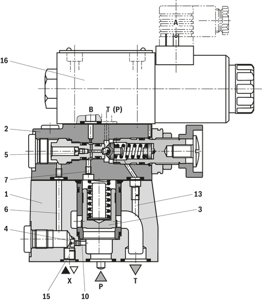
The pressure valve type DBW is a pilot-operated pressure relief valve.
They are used for limiting and solenoid-actuated unloading the operating pressure.
The valve basically consists of the main valve (1) with main spool insert (3) and pilot control valve (2) with pressure adjustment element and one integrated directional spool valve (16).
The function of this valve is basically the same as that of valve type DB. The unloading of the main spool (3) is, however, achieved by controlling the mounted directional spool valve (16).
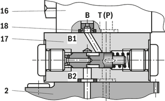
Pressure relief valve with switching shock damping (sandwich plate), version "DBW.../..S6...R12"
The opening of the connection from B2 to B1 is delayed by means of the switching shock damping valve (17). Pressure peaks and acoustic decompression shocks in the return line are thus avoided. It is installed between the pilot control valve (2) and the directional valve (16).
The degree of damping (decompression shock) is determined by the size of the nozzle (18). Nozzle Ø1.2 mm (ordering code "R12") is recommended.
The pressure valve type DBW is a pilot-operated pressure relief valve.
They are used for limiting and solenoid-actuated unloading the operating pressure.
The valve basically consists of the main valve (1) with main spool insert (3) and pilot control valve (2) with pressure adjustment element and one integrated directional spool valve (16).
The function of this valve is basically the same as that of valve type DB. The unloading of the main spool (3) is, however, achieved by controlling the mounted directional spool valve (16).
Pressure relief valve with switching shock damping (sandwich plate), version "DBW.../..S6...R12"
The opening of the connection from B2 to B1 is delayed by means of the switching shock damping valve (17). Pressure peaks and acoustic decompression shocks in the return line are thus avoided. It is installed between the pilot control valve (2) and the directional valve (16).
The degree of damping (decompression shock) is determined by the size of the nozzle (18). Nozzle Ø1.2 mm (ordering code "R12") is recommended.
01 | 02 | 03 | 04 | 05 | 06 | 07 | 08 | 09 | 10 | 11 | 12 | 13 | 14 | 15 | 16 | 17 | 18 | 19 | 20 | 21 | 22 | |
DB | W | 5X | / | K4 | * |
01 | Pressure relief valve | DB |
02 | With attached directional valve | W |
03 | Pilot-operated valve (complete) | no code |
Pilot control valve without main spool insert (do not enter any size) | C | |
Pilot control valve with main spool insert (enter size 10 or 30) | C | |
Pilot control valve without main spool insert for subplate mounting (do not enter any size) | T 1) | |
04 | Size 10 | |
Subplate mounting "no code" | 10 | |
Threaded connection "G" | 10 (G1/2) | |
Size 16 | ||
Threaded connection "G" | 15 (G3/4) | |
Size 25 | ||
Subplate mounting "no code" | 20 | |
Threaded connection "G" | 20 (G1) | |
Threaded connection "G" | 25 (G1 1/4) | |
Size 32 | ||
Subplate mounting "no code" | 30 | |
Threaded connection "G" | 30 (G1 1/2) | |
05 | Normally closed | A |
Normally open | B | |
Type of connection | ||
06 | Subplate mounting or cartridge valve | no code |
For threaded connection | G | |
Adjustment type for pressure adjustment | ||
07 | Rotary knob (not for version "C" and "T") | 1 |
Sleeve with hexagon and protective cap | 2 | |
Lockable rotary knob with scale | 3 2) | |
Rotary knob with scale | 7 | |
08 | Main spool Ø24 mm (all sizes) | – |
Main spool Ø28 mm (only for NG32) | N | |
09 | Component series 50 … 59 (50 … 59: unchanged installation and connection dimensions) | 5X |
10 | Set pressure up to 50 bar | 50 |
Set pressure up to 100 bar | 100 | |
Set pressure up to 200 bar | 200 | |
Set pressure up to 315 bar | 315 | |
Set pressure up to 350 bar | 350 | |
Pilot oil flow | ||
11 | External pilot oil supply, internal pilot oil return | X 3) |
Internal pilot oil supply, external pilot oil return | Y | |
Pilot oil supply and pilot oil return external | XY 3) | |
12 | Standard version | no code |
Valve for minimum cracking pressure (not for versions "without main spool insert" and not suitable for mutual relief) | U 4) | |
13 | Without switching shock damping | no code |
With switching shock damping | S | |
14 | With directional spool valve (data sheet 23178) | 6E |
With directional seat valve (data sheet 22058) | 6SM | |
15 | Direct voltage 24 V | G24 |
Alternating voltage 230 V, 50/60 Hz | W230 | |
16 | Without manual override | no code |
With concealed manual override | N9 | |
With manual override | N | |
Electrical connection | ||
17 | Connector DIN EN 175301-803 | K4 5) |
18 | Nozzle Ø1,2 mm in channel B of the directional spool valve (version "6E") | R12 6) |
Nozzle Ø1,2 mm in channel P of the directional seat valve (version "6SM") | B12 6) | |
Corrosion resistance | ||
19 | None | no code |
Seal material | ||
20 | NBR seals | no code |
FKM seals | V | |
Observe compatibility of seals with hydraulic fluid used. (Other seals upon request) | ||
Equipment Directive | ||
21 | Without type-examination procedure | no code |
Type-examination tested safety valve according to Pressure Equipment Directive 2014/68/EU | E | |
22 | Further details in the plain text | * |
| 1) | DBT corresponds to DBC, however with closed central bore |
| 2) | H-Key with material no. R900008158 is included in the scope of delivery. |
| 3) | Not with version "DBC" |
| 4) | Only possible up to pressure rating 315 bar |
| 5) | Mating connectors, separate order, see "Accessories" |
| 6) | Ordering code only necessary with version with attached directional valve and switching shock damping ("S") |
(Component series 5X according to Pressure Equipment Directive 2014/68/EU)
NG | Type designation | Component marking | Maximum flow qVmax in l/min with pilot oil return | Set response overpressure p in bar | |
external "Y" | internal "–" | ||||
10 |  | TÜV.SV.▢ – 851.12.F.G.p | 170 230 230 230 | 130 200 200 200 | 30 ... 60 61 ... 110 111 ... 210 211 ... 350 |
25 |  | TÜV.SV.▢ – 852.22.F.G.p | 250 270 420 450 | 180 210 320 400 | 30 ... 60 61 ... 110 111 ... 210 211 ... 350 |
32 |  | TÜV.SV.▢ – 853.32.F.G.p | 600 600 650 700 | 225 340 540 580 | 30 ... 60 61 ... 110 111 ... 210 211 ... 350 |
1 | Directional valve, normally closed | A |
Directional valve, normally open | B | |
2 | For subplate mounting | no code |
For threaded connection | G | |
Adjustment type for pressure adjustment | ||
3 | Hand wheel (pressure adjustment sealed, unloading or setting of a lower response pressure possible!) | 1 |
With sealed protective cap (no adjustment/unloading possible) | 2 | |
Pressure | ||
4 | To be entered by the customer, e.g. pressure adjustment ≥ 30 bar and possible in 5 bar steps. | e.g. 150 |
Pilot oil flow | ||
5 | Pilot oil supply internal, pilot oil return internal | no code |
Pilot oil supply internal, pilot oil return external (Recommendation) | Y 1) | |
Electrical specifications | ||
6 | see Type code above | e.g. EG24N9K4 |
7 | NBR seals | no code |
FKM seals | V | |
▢ | Value entered at the factory | |
| 1) | Pilot oil supply external "X" not possible |
01 | 02 | 03 | 04 | 05 | 06 | 07 | 08 | 09 | 10 | 11 | 12 | 13 | 14 | 15 | 16 | 17 | 18 | 19 | 20 | 21 | 22 | |
DB | W | 5X | / | K4 | * |
01 | Pressure relief valve | DB |
02 | With attached directional valve | W |
03 | Pilot-operated valve (complete) | no code |
Pilot control valve without main spool insert (do not enter any size) | C | |
Pilot control valve with main spool insert (enter size 10 or 30) | C | |
Pilot control valve without main spool insert for subplate mounting (do not enter any size) | T 1) | |
04 | Size 10 | |
Subplate mounting "no code" | 10 | |
Threaded connection "G" | 10 (G1/2) | |
Size 16 | ||
Threaded connection "G" | 15 (G3/4) | |
Size 25 | ||
Subplate mounting "no code" | 20 | |
Threaded connection "G" | 20 (G1) | |
Threaded connection "G" | 25 (G1 1/4) | |
Size 32 | ||
Subplate mounting "no code" | 30 | |
Threaded connection "G" | 30 (G1 1/2) | |
05 | Normally closed | A |
Normally open | B | |
Type of connection | ||
06 | Subplate mounting or cartridge valve | no code |
For threaded connection | G | |
Adjustment type for pressure adjustment | ||
07 | Rotary knob (not for version "C" and "T") | 1 |
Sleeve with hexagon and protective cap | 2 | |
Lockable rotary knob with scale | 3 2) | |
Rotary knob with scale | 7 | |
08 | Main spool Ø24 mm (all sizes) | – |
Main spool Ø28 mm (only for NG32) | N | |
09 | Component series 50 … 59 (50 … 59: unchanged installation and connection dimensions) | 5X |
10 | Set pressure up to 50 bar | 50 |
Set pressure up to 100 bar | 100 | |
Set pressure up to 200 bar | 200 | |
Set pressure up to 315 bar | 315 | |
Set pressure up to 350 bar | 350 | |
Pilot oil flow | ||
11 | External pilot oil supply, internal pilot oil return | X 3) |
Internal pilot oil supply, external pilot oil return | Y | |
Pilot oil supply and pilot oil return external | XY 3) | |
12 | Standard version | no code |
Valve for minimum cracking pressure (not for versions "without main spool insert" and not suitable for mutual relief) | U 4) | |
13 | Without switching shock damping | no code |
With switching shock damping | S | |
14 | With directional spool valve (data sheet 23178) | 6E |
With directional seat valve (data sheet 22058) | 6SM | |
15 | Direct voltage 24 V | G24 |
Alternating voltage 230 V, 50/60 Hz | W230 | |
16 | Without manual override | no code |
With concealed manual override | N9 | |
With manual override | N | |
Electrical connection | ||
17 | Connector DIN EN 175301-803 | K4 5) |
18 | Nozzle Ø1,2 mm in channel B of the directional spool valve (version "6E") | R12 6) |
Nozzle Ø1,2 mm in channel P of the directional seat valve (version "6SM") | B12 6) | |
Corrosion resistance | ||
19 | None | no code |
Seal material | ||
20 | NBR seals | no code |
FKM seals | V | |
Observe compatibility of seals with hydraulic fluid used. (Other seals upon request) | ||
Equipment Directive | ||
21 | Without type-examination procedure | no code |
Type-examination tested safety valve according to Pressure Equipment Directive 2014/68/EU | E | |
22 | Further details in the plain text | * |
| 1) | DBT corresponds to DBC, however with closed central bore |
| 2) | H-Key with material no. R900008158 is included in the scope of delivery. |
| 3) | Not with version "DBC" |
| 4) | Only possible up to pressure rating 315 bar |
| 5) | Mating connectors, separate order, see "Accessories" |
| 6) | Ordering code only necessary with version with attached directional valve and switching shock damping ("S") |
(Component series 5X according to Pressure Equipment Directive 2014/68/EU)
NG | Type designation | Component marking | Maximum flow qVmax in l/min with pilot oil return | Set response overpressure p in bar | |
external "Y" | internal "–" | ||||
10 | | TÜV.SV.▢ – 851.12.F.G.p | 170 230 230 230 | 130 200 200 200 | 30 ... 60 61 ... 110 111 ... 210 211 ... 350 |
25 | | TÜV.SV.▢ – 852.22.F.G.p | 250 270 420 450 | 180 210 320 400 | 30 ... 60 61 ... 110 111 ... 210 211 ... 350 |
32 | | TÜV.SV.▢ – 853.32.F.G.p | 600 600 650 700 | 225 340 540 580 | 30 ... 60 61 ... 110 111 ... 210 211 ... 350 |
1 | Directional valve, normally closed | A |
Directional valve, normally open | B | |
2 | For subplate mounting | no code |
For threaded connection | G | |
Adjustment type for pressure adjustment | ||
3 | Hand wheel (pressure adjustment sealed, unloading or setting of a lower response pressure possible!) | 1 |
With sealed protective cap (no adjustment/unloading possible) | 2 | |
Pressure | ||
4 | To be entered by the customer, e.g. pressure adjustment ≥ 30 bar and possible in 5 bar steps. | e.g. 150 |
Pilot oil flow | ||
5 | Pilot oil supply internal, pilot oil return internal | no code |
Pilot oil supply internal, pilot oil return external (Recommendation) | Y 1) | |
Electrical specifications | ||
6 | see Type code above | e.g. EG24N9K4 |
7 | NBR seals | no code |
FKM seals | V | |
▢ | Value entered at the factory | |
| 1) | Pilot oil supply external "X" not possible |
Size | 10 | 16 | 25 | 32 | ||||
| DB.. 15 | DB.. 20 | DB.. 25 | ||||||
Weight | Subplate mounting | DBW... | kg | 4.05 | - | 4.95 | - | 5.85 |
DBWC... | kg | 2.65 | ||||||
DBWC 10 or 30 ... | kg | 2.95 | ||||||
Threaded connection | DBW...G | kg | 6.75 | 6.65 | 6.55 | 6.45 | 6.25 | |
Installation position | any | |||||||
Ambient temperature range | NBR seals | °C | -30 … +50 | |||||
FKM seals | °C | -15 … +50 | ||||||
Minimum stability of the housing materials | with subplate mounting and version "DBWC" | Housing materials are to be selected so that there is sufficient safety for all imaginable operating conditions (e.g. with regard to pressure resistance, thread stripping strengths and tightening torques). | ||||||
Size | 10 | 16 | 25 | 25 | 32 | ||
Maximum operating pressure | Port P | bar | 350 | ||||
Port X | bar | 350 | |||||
Port T | bar | 315 | |||||
Maximum counter pressure | Port Y (DC solenoid) | bar | 210 | ||||
Port Y (AC solenoid) | bar | 160 | |||||
Port T (DC solenoid) | bar | 210 | |||||
Port T (AC solenoid) | bar | 160 | |||||
Minimum set pressure | flow-dependent, see "characteristic curves" | ||||||
Maximum set pressure | bar | 50 100 200 315 350 | |||||
Maximum flow | Subplate mounting | l/min | 250 | - | 500 | - | 650 |
Threaded connection | l/min | 250 | 500 | 650 | |||
Hydraulic fluid | see table | ||||||
Hydraulic fluid temperature range | NBR seals | °C | -30 … +80 | ||||
FKM seals | °C | -15 … +80 | |||||
Viscosity range | mm²/s | 10 … 800 | |||||
Maximum admissible degree of contamination of the hydraulic fluid 1) | Class 20/18/15 according to ISO 4406 (c) | ||||||
| 1) | The cleanliness classes specified for the components must be adhered to in hydraulic systems. Effective filtration prevents faults and simultaneously increases the life cycle of the components. For the selection of the filters, see www.boschrexroth.com/filter. |
Notes:
Tank preloading adds to the minimum set pressure (ports T and Y)
Technical data for directional seat valve see data sheet 22058, for directional spool valve data sheet 23178.
Hydraulic fluid | Classification | Suitable sealing materials | Standards | Data sheet | |
Mineral oils | HL, HLP | NBR, FKM | DIN 51524 | 90220 | |
Bio-degradable 1) | Insoluble in water | HETG | FKM | ISO 15380 | 90221 |
HEES | FKM | ||||
Soluble in water | HEPG | FKM | ISO 15380 | ||
Flame-resistant | Water-free | HFDU (glycol base) | FKM | ISO 12922 | 90222 |
HFDU (ester base) 1) | FKM | ||||
Important information on hydraulic fluids:
| |||||
| 1) | Not recommended for corrosion-protected version “J3” |
(Component series 5X according to Pressure Equipment Directive 2014/68/EU)
Version | Pilot oil flow "no code" | Pilot oil flow "Y" | ||
Maximum counter pressure | Port Y | bar | - | 0 |
Port T | bar | See characteristic curves and explanatory notes for maximum counter pressure | PT < 15 | |
Maximum flow | See ordering code, safety instructions and characteristic curves "Type-examination tested safety valve" | |||
Hydraulic fluid | Mineral oil (HL, HLP) according to DIN 51524 and DIN 51524-1 | |||
Hydraulic fluid temperature range | °C | -10 … +60 | ||
Viscosity range | mm²/s | 12 … 230 | ||
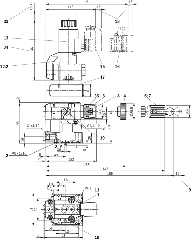
Dimensions in mm
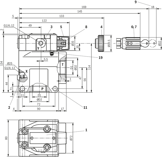
1 | Name plate |
2 | X port for pilot oil supply, external |
3 | Y port for pilot oil return, external |
4 | Adjustment type "1" |
5 | Adjustment type "2" |
6 | Adjustment type "3" |
7 | Adjustment type "7" |
8 | Hexagon SW10 |
9 | Space required to remove the key |
11 | Valve mounting bores |
19 | Omitted with internal pilot oil return |
Version | D1 | ØD2 | T1 |
mm | mm | ||
| "DB 10 G" | G1/2 | 34 | 14 |
| "DB 15 G" | G3/4 | 42 | 16 |
| "DB 20 G" | G1 | 47 | 18 |
| "DB 25 G" | G1 1/4 | 58 | 20 |
| "DB 30 G" | G1 1/2 | 65 | 22 |
Dimensions for attached directional valve see "Subplate mounting"
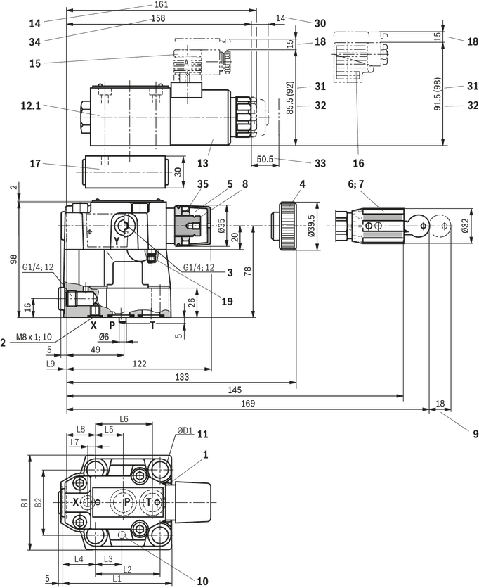
1 | Name plate |
2 | X port for pilot oil supply, external |
3 | Y port for pilot oil return, external |
4 | Adjustment type "1" |
5 | Adjustment type "2" |
6 | Adjustment type "3" |
7 | Adjustment type "7" |
8 | Hexagon SW10 |
9 | Space required to remove the key |
10 | Locking pin |
11 | Valve mounting bores |
12.1 | Directional spool valve NG6 |
13 | Solenoid “a” |
14 | Dimension for valve without manual override |
15 | Mating connector without circuitry (separate order) |
16 | Mating connector with circuitry (separate order) |
17 | Switching shock damping valve, optional |
18 | Space required to remove the mating connector |
19 | Omitted with internal pilot oil return |
30 | Dimension for solenoid with manual override “N” |
31 | Dimension ( ) for valve with AC solenoid |
32 | Dimension for valve with DC solenoid |
33 | Space required to remove the solenoid coil |
34 | Dimension for valve with concealed manual override "N9" |
35 | Lock nut SW17, tightening torque MA = 10+5 Nm |
Version | L1 | L2 | L3 | L4 | L5 | L6 | L7 | L8 | L9 | B1 | B2 | ØD1 |
mm | mm | mm | mm | mm | mm | mm | mm | mm | mm | mm | mm | |
| "DB 10" | 91 | 53.8 | 22.1 | 27.5 | 22.1 | 47.5 | 0 | 25.5 | 2 | 78 | 53.8 | 14 |
| "DB 20" | 116 | 66.7 | 33.4 | 33.3 | 11.1 | 55.6 | 23.8 | 22.8 | 10.5 | 100 | 70 | 18 |
| "DB 30" | 147.5 | 88.9 | 44.5 | 41 | 12.7 | 76.2 | 31.8 | 20 | 21 | 115 | 82.6 | 20 |
1 | Name plate |
2 | X port for pilot oil supply, external |
3 | Y port for pilot oil return, external |
4 | Adjustment type "1" |
5 | Adjustment type "2" |
6 | Adjustment type "3" |
7 | Adjustment type "7" |
8 | Hexagon SW10 |
9 | Space required to remove the key |
10 | Locking pin |
11 | Valve mounting bores |
12.2 | Directional seat valve NG6 |
13 | Solenoid “a” |
14 | Dimension for valve without manual override |
15 | Mating connector without circuitry (separate order) |
16 | Mating connector with circuitry (separate order) |
17 | Switching shock damping valve, optional |
18 | Space required to remove the mating connector |
19 | Omitted with internal pilot oil return |
30 | Dimension for solenoid with manual override “N” |
31 | Dimension ( ) for valve with AC solenoid |
32 | Dimension for valve with DC solenoid |
33 | Space required to remove the solenoid coil |
34 | Dimension for valve with concealed manual override "N9" |
35 | Lock nut SW17, tightening torque MA = 10+5 Nm |
Dimensions in mm
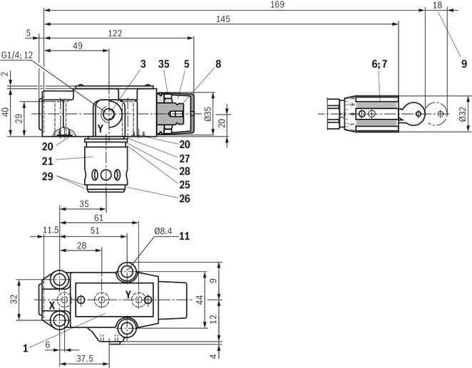
Dimensions for attached directional valve see "Subplate mounting"
Dimensions in mm
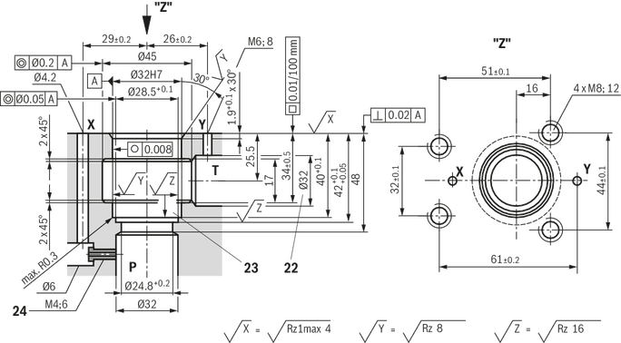
1 | Name plate |
3 | Y port for pilot oil return, external |
5 | Adjustment type "2" |
6 | Adjustment type "3" |
7 | Adjustment type "7" |
8 | Hexagon SW10 |
9 | Space required to remove the key |
11 | Valve mounting bores |
20 | Seal ring |
21 | Main spool insert |
22 | Bore Ø32 mm can cut Ø45 mm at any point. However, it must be observed that the connection bore X and the mounting bore are not damaged! |
23 | Support ring and seal ring are to be inserted into this bore before assembly of the main spool. |
24 | Nozzle (separate order; recommended nozzle Ø1.0 mm) |
25 | Seal ring |
26 | Seal ring |
27 | Seal ring |
28 | Support ring |
29 | Support ring |
35 | Lock nut SW17, tightening torque MA = 10+5 Nm |
Valve mounting screws (separate order)
For reasons of stability, exclusively the following valve mounting screws may be used:
Version "DB 10"
4 x ISO 4762 - M12 x 50 - 10.9-flZn/nc/480h/C
with friction coefficient μtotal = 0.09 … 0.14
tightening torque MA = 75 Nm ±10%
material no. R913015611
Version "DB 20"
4 x ISO 4762 - M16 x 50 - 10.9-flZn/nc/480h/C
with friction coefficient μtotal = 0.09 … 0.14
tightening torque MA = 185 Nm ±10%
material no. R913015664
Version "DB 30"
4 x DIN 912 - M18 x 50 - 10.9-flZn/nc/480h/C
with friction coefficient μtotal = 0.09 … 0.14
tightening torque MA = 248 Nm ±10%
material no. R913015903
Version "DBC", "DBC 10", "DBC 30" and "DBT"
4 x ISO 4762 - M8 x 40 - 10.9-flZn/nc/480h/C
with friction coefficient μtotal = 0.09 … 0.14
tightening torque MA = 31 Nm ±10%
material no. R913015798
Notice:
The tightening torques stated are guidelines when using screws with the specified friction coefficients and when using a manual torque wrench (tolerance ±10%).
 |
Required surface quality of the valve contact surface |
Dimensions in mm
1 | Name plate |
2 | X port for pilot oil supply, external |
3 | Y port for pilot oil return, external |
4 | Adjustment type "1" |
5 | Adjustment type "2" |
6 | Adjustment type "3" |
7 | Adjustment type "7" |
8 | Hexagon SW10 |
9 | Space required to remove the key |
11 | Valve mounting bores |
19 | Omitted with internal pilot oil return |
Version | D1 | ØD2 | T1 |
mm | mm | ||
| "DB 10 G" | G1/2 | 34 | 14 |
| "DB 15 G" | G3/4 | 42 | 16 |
| "DB 20 G" | G1 | 47 | 18 |
| "DB 25 G" | G1 1/4 | 58 | 20 |
| "DB 30 G" | G1 1/2 | 65 | 22 |
Dimensions for attached directional valve see "Subplate mounting"
1 | Name plate |
2 | X port for pilot oil supply, external |
3 | Y port for pilot oil return, external |
4 | Adjustment type "1" |
5 | Adjustment type "2" |
6 | Adjustment type "3" |
7 | Adjustment type "7" |
8 | Hexagon SW10 |
9 | Space required to remove the key |
10 | Locking pin |
11 | Valve mounting bores |
12.1 | Directional spool valve NG6 |
13 | Solenoid “a” |
14 | Dimension for valve without manual override |
15 | Mating connector without circuitry (separate order) |
16 | Mating connector with circuitry (separate order) |
17 | Switching shock damping valve, optional |
18 | Space required to remove the mating connector |
19 | Omitted with internal pilot oil return |
30 | Dimension for solenoid with manual override “N” |
31 | Dimension ( ) for valve with AC solenoid |
32 | Dimension for valve with DC solenoid |
33 | Space required to remove the solenoid coil |
34 | Dimension for valve with concealed manual override "N9" |
35 | Lock nut SW17, tightening torque MA = 10+5 Nm |
Version | L1 | L2 | L3 | L4 | L5 | L6 | L7 | L8 | L9 | B1 | B2 | ØD1 |
mm | mm | mm | mm | mm | mm | mm | mm | mm | mm | mm | mm | |
| "DB 10" | 91 | 53.8 | 22.1 | 27.5 | 22.1 | 47.5 | 0 | 25.5 | 2 | 78 | 53.8 | 14 |
| "DB 20" | 116 | 66.7 | 33.4 | 33.3 | 11.1 | 55.6 | 23.8 | 22.8 | 10.5 | 100 | 70 | 18 |
| "DB 30" | 147.5 | 88.9 | 44.5 | 41 | 12.7 | 76.2 | 31.8 | 20 | 21 | 115 | 82.6 | 20 |
1 | Name plate |
2 | X port for pilot oil supply, external |
3 | Y port for pilot oil return, external |
4 | Adjustment type "1" |
5 | Adjustment type "2" |
6 | Adjustment type "3" |
7 | Adjustment type "7" |
8 | Hexagon SW10 |
9 | Space required to remove the key |
10 | Locking pin |
11 | Valve mounting bores |
12.2 | Directional seat valve NG6 |
13 | Solenoid “a” |
14 | Dimension for valve without manual override |
15 | Mating connector without circuitry (separate order) |
16 | Mating connector with circuitry (separate order) |
17 | Switching shock damping valve, optional |
18 | Space required to remove the mating connector |
19 | Omitted with internal pilot oil return |
30 | Dimension for solenoid with manual override “N” |
31 | Dimension ( ) for valve with AC solenoid |
32 | Dimension for valve with DC solenoid |
33 | Space required to remove the solenoid coil |
34 | Dimension for valve with concealed manual override "N9" |
35 | Lock nut SW17, tightening torque MA = 10+5 Nm |
Dimensions in mm
Dimensions for attached directional valve see "Subplate mounting"
Dimensions in mm
1 | Name plate |
3 | Y port for pilot oil return, external |
5 | Adjustment type "2" |
6 | Adjustment type "3" |
7 | Adjustment type "7" |
8 | Hexagon SW10 |
9 | Space required to remove the key |
11 | Valve mounting bores |
20 | Seal ring |
21 | Main spool insert |
22 | Bore Ø32 mm can cut Ø45 mm at any point. However, it must be observed that the connection bore X and the mounting bore are not damaged! |
23 | Support ring and seal ring are to be inserted into this bore before assembly of the main spool. |
24 | Nozzle (separate order; recommended nozzle Ø1.0 mm) |
25 | Seal ring |
26 | Seal ring |
27 | Seal ring |
28 | Support ring |
29 | Support ring |
35 | Lock nut SW17, tightening torque MA = 10+5 Nm |
Valve mounting screws (separate order)
For reasons of stability, exclusively the following valve mounting screws may be used:
Version "DB 10"
4 x ISO 4762 - M12 x 50 - 10.9-flZn/nc/480h/C
with friction coefficient μtotal = 0.09 … 0.14
tightening torque MA = 75 Nm ±10%
material no. R913015611
Version "DB 20"
4 x ISO 4762 - M16 x 50 - 10.9-flZn/nc/480h/C
with friction coefficient μtotal = 0.09 … 0.14
tightening torque MA = 185 Nm ±10%
material no. R913015664
Version "DB 30"
4 x DIN 912 - M18 x 50 - 10.9-flZn/nc/480h/C
with friction coefficient μtotal = 0.09 … 0.14
tightening torque MA = 248 Nm ±10%
material no. R913015903
Version "DBC", "DBC 10", "DBC 30" and "DBT"
4 x ISO 4762 - M8 x 40 - 10.9-flZn/nc/480h/C
with friction coefficient μtotal = 0.09 … 0.14
tightening torque MA = 31 Nm ±10%
material no. R913015798
Notice:
The tightening torques stated are guidelines when using screws with the specified friction coefficients and when using a manual torque wrench (tolerance ±10%).
| |
Required surface quality of the valve contact surface |


