| Availability: | |
|---|---|
| Quantity: | |

DBDS10K1X/400
Rexroth
R900424152
As screw-in cartridge valve (cartridge)
For threaded connection
For subplate mounting
Adjustment type for pressure adjustment, optionally:
‒ Sleeve with hexagon and protective cap
‒ Rotary knob
‒ Hand wheel
‒ Lockable rotary knob
As screw-in cartridge valve (cartridge)
For threaded connection
For subplate mounting
Adjustment type for pressure adjustment, optionally:
‒ Sleeve with hexagon and protective cap
‒ Rotary knob
‒ Hand wheel
‒ Lockable rotary knob
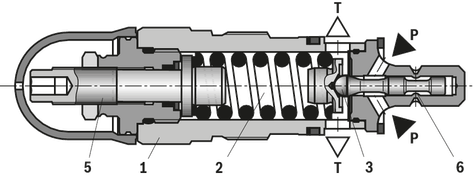
Pressure relief valves of type DBD are direct operated seat valves. They are used for limiting a system pressure.
The valves basically consist of sleeve (1), spring (2), poppet with damping piston (3) (pressure rating 25 bar … 400 bar) or ball (4) (pressure rating 630 bar) and adjustment type (5). The system pressure can be set steplessly via the adjustment type (5). The spring (2) pushes the poppet (3) or the ball (4) onto the seat. Channel P is connected to the system. The pressure existing in the system acts on the poppet surface (or the ball). If the pressure in channel P exceeds the value set at the spring (2), the poppet (3) or the ball (4) opens against the spring (2). Now, hydraulic fluid from channel P flows into channel T. The stroke of the poppet (3) is limited by the embossing (6).
In order to achieve good pressure adjustment over the entire pressure range, the entire pressure range has been divided into 7 pressure ratings. One pressure rating corresponds to a certain spring for a maximum operating pressure that can be set by means of that spring.
Notices:
The adjustment type (5) is constructed so that it cannot be lost. Due to the gimbal-mounting, the adjustment element remains loose (movable) in the adjustment type (5) in case of complete unloading.
Pressure rating “25”: If despite completely unloaded adjustment type, the minimum pressure does not settle, the adjustment element has to be “pulled back” to the stop due to the low spring and/or restoring force.
For pressure adjustment / increase, the adjustment element can then be screwed in again.
Version pressure rating 25 … 400 bar (poppet seat valve)
Version pressure rating 630 bar (ball seat valve, only NG10)
01 |
02 |
03 |
04 |
05 |
06 |
07 |
08 |
09 |
10 |
11 |
|
DBD |
1X |
/ |
* |
01 |
Pressure relief valve, direct controlled |
DBD |
|||||||
Adjustment type for pressure adjustment |
|||||||||
02 |
NG6 |
NG8 |
NG10 |
NG15 |
NG20 |
NG25 |
NG30 |
||
Sleeve with hexagon and protective cap |
✔ |
✔ |
✔ |
✔ |
✔ |
✔ |
✔ |
S |
|
Rotary knob 1) |
✔ |
✔ |
✔ |
✔ |
✔ |
– |
– |
H |
|
Hand wheel 2) |
– |
– |
– |
– |
– |
✔ |
✔ |
H |
|
Lockable rotary knob 1; ,3; 4) |
✔ |
✔ |
✔ |
✔ |
✔ |
– |
– |
A |
|
03 |
Size 6 (connection G1/4) |
6 |
|||||||
Size 8 (connection G3/8) |
8 |
||||||||
Size 10 (connection G1/2) |
10 |
||||||||
Size 15 (connection G3/4) |
15 |
||||||||
Size 20 (connection G1) |
20 |
||||||||
Size 25 (connection G1 1/4) |
25 |
||||||||
Size 30 (connection G1 1/2) |
30 |
||||||||
Type of connection |
|||||||||
04 |
NG6 |
NG8 |
NG10 |
NG15 |
NG20 |
NG25 |
NG30 |
||
As screw-in cartridge valve (cartridge) |
✔ |
– |
✔ |
– |
✔ |
– |
✔ |
K |
|
For threaded connection |
✔ |
✔ |
✔ |
✔ |
✔ |
✔ |
✔ |
G |
|
For subplate mounting |
✔ |
– |
✔ |
– |
✔ |
– |
✔ |
P |
|
05 |
Component series 10 ... 1Z (10 ... 1Z: unchanged installation and connection dimensions) |
1X |
|||||||
Pressure rating 5) |
|||||||||
06 |
NG6 |
NG8 |
NG10 |
NG15 |
NG20 |
NG25 |
NG30 |
||
Set pressure up to 25 bar |
✔ |
✔ |
✔ |
✔ |
✔ |
✔ |
✔ |
25 |
|
Set pressure up to 50 bar |
✔ |
✔ |
✔ |
✔ |
✔ |
✔ |
✔ |
50 |
|
Set pressure up to 100 bar |
✔ |
✔ |
✔ |
✔ |
✔ |
✔ |
✔ |
100 |
|
Set pressure up to 200 bar |
✔ |
✔ |
✔ |
✔ |
✔ |
✔ |
✔ |
200 |
|
Set pressure up to 315 bar |
✔ |
✔ |
✔ |
✔ |
✔ |
✔ |
✔ |
315 |
|
Set pressure up to 400 bar |
✔ |
✔ |
✔ |
✔ |
✔ |
– |
– |
400 |
|
Set pressure up to 630 bar 6) |
– |
– |
✔ |
– |
– |
– |
– |
630 |
|
Corrosion resistance (For availability see table below) |
|||||||||
07 |
None |
no code |
|||||||
Improved corrosion protection (240 h salt spray test according to EN ISO 9227) |
J3 |
||||||||
High corrosion protection (720 h salt spray test according to EN ISO 9227) |
J5 |
||||||||
Seal material (observe compatibility of seals with hydraulic fluid used, see "Technical data") |
|||||||||
08 |
NBR seals |
no code |
|||||||
FKM seals |
V |
||||||||
Line connection |
|||||||||
09 |
Pipe thread according to ISO 228-1 |
no code |
|||||||
SAE thread |
12 |
||||||||
Equipment Directive |
|||||||||
10 |
Without type-examination procedure |
no code |
|||||||
Type-examination tested safety valve according to Pressure Equipment Directive 2014/68/EU |
E |
||||||||
11 |
Further details in the plain text |
||||||||
| 1) | For size 20, only available for the pressure ratings "25", "50" or "100". |
| 2) | Pressure ratings "25", "50" or "100" only. |
| 3) | Key with material no. R900008158 is included in the scope of delivery. |
| 4) | Not for type-examination tested safety valves. |
| 5) | When selecting the pressure rating, please observe the characteristic curves. |
| 6) | With version "G" and "P", only available as "SO292", see "dimensions". |
Type of connection |
NG6 |
NG8 |
NG10 |
NG15 |
NG20 |
NG25 |
NG30 |
As cartridge valve ("K") |
no code, J5 |
– |
no code, J5 |
– |
no code, J5 |
– |
no code, J5 |
For threaded connection ("G") |
no code, J3 |
no code |
no code, J3 |
no code |
no code, J3 |
no code |
no code, J3 |
For subplate mounting ("P") |
no code, J3 |
– |
no code, J3 |
– |
no code, J3 |
– |
no code, J3 |
(Component series 1X, according to the Pressure Equipment Directive 2014/68/EU)
Size |
Type designation |
Component marking |
6 |

|
TÜV.SV.▢–849.5.F.αw.p. |
TÜV.SV.▢–849.5.F.G.p. |
||
10 |

|
TÜV.SV.▢–850.6.F.αw.p. |
TÜV.SV.▢–850.6.F.G.p. |
||
TÜV.SV.▢–390.4,5.F.30.p. 1) |
||
20 |

|
TÜV.SV.▢–361.10.F.αw.p. |
30 |

|
TÜV.SV.▢–362.15.F.αw.p. |
▢ Information is entered at the factory |
||
| 1) | Component marking for DBD. 10.1X/...; 400 bar < p ≤ 630 bar |
Adjustment type for pressure adjustment |
||||||
01 |
NG6 |
NG10 |
NG20 |
NG30 |
||
Sleeve with hexagon and protective cap |
✔ |
✔ |
✔ |
✔ |
S |
|
Rotary knob |
✔ |
✔ |
✔ |
– |
H |
|
Hand wheel |
– |
– |
– |
✔ |
H |
|
Type of connection |
||||||
02 |
NG6 |
NG10 |
NG20 |
NG30 |
||
As screw-in cartridge valve (cartridge) |
✔ |
✔ |
✔ |
✔ |
K |
|
For threaded connection |
✔ |
✔ |
✔ |
✔ |
G |
|
For subplate mounting |
✔ |
✔ |
✔ |
✔ |
P |
|
Pressure rating 1) |
||||||
03 |
In the type designation, the pressure is to be entered by the customer. Pressure adjustments ≥ 30 bar and in 5 bar steps possible. |
|||||
Corrosion resistance (For availability see table below) |
||||||
04 |
None |
no code |
||||
Improved corrosion protection (240 h salt spray test according to EN ISO 9227) |
J3 |
|||||
High corrosion protection (720 h salt spray test according to EN ISO 9227) |
J5 |
|||||
Seal material (observe compatibility of seals with hydraulic fluid used, see "Technical data") |
||||||
05 |
NBR seals |
no code |
||||
FKM seals |
V |
|||||
Line connection |
||||||
06 |
Pipe thread according to ISO 228-1 |
no code |
||||
| 1) | When selecting the pressure rating, please observe the characteristic curves. |
Type of connection |
NG6 |
NG10 |
NG20 |
NG30 |
As cartridge valve ("K") |
no code, J5 |
no code, J5 |
no code, J5 |
no code, J5 |
For threaded connection ("G") |
no code, J3 |
no code, J3 |
no code, J3 |
no code, J3 |
01 |
02 |
03 |
04 |
05 |
06 |
07 |
08 |
09 |
10 |
11 |
|
DBD |
1X |
/ |
* |
01 |
Pressure relief valve, direct controlled |
DBD |
|||||||
Adjustment type for pressure adjustment |
|||||||||
02 |
NG6 |
NG8 |
NG10 |
NG15 |
NG20 |
NG25 |
NG30 |
||
Sleeve with hexagon and protective cap |
✔ |
✔ |
✔ |
✔ |
✔ |
✔ |
✔ |
S |
|
Rotary knob 1) |
✔ |
✔ |
✔ |
✔ |
✔ |
– |
– |
H |
|
Hand wheel 2) |
– |
– |
– |
– |
– |
✔ |
✔ |
H |
|
Lockable rotary knob 1; ,3; 4) |
✔ |
✔ |
✔ |
✔ |
✔ |
– |
– |
A |
|
03 |
Size 6 (connection G1/4) |
6 |
|||||||
Size 8 (connection G3/8) |
8 |
||||||||
Size 10 (connection G1/2) |
10 |
||||||||
Size 15 (connection G3/4) |
15 |
||||||||
Size 20 (connection G1) |
20 |
||||||||
Size 25 (connection G1 1/4) |
25 |
||||||||
Size 30 (connection G1 1/2) |
30 |
||||||||
Type of connection |
|||||||||
04 |
NG6 |
NG8 |
NG10 |
NG15 |
NG20 |
NG25 |
NG30 |
||
As screw-in cartridge valve (cartridge) |
✔ |
– |
✔ |
– |
✔ |
– |
✔ |
K |
|
For threaded connection |
✔ |
✔ |
✔ |
✔ |
✔ |
✔ |
✔ |
G |
|
For subplate mounting |
✔ |
– |
✔ |
– |
✔ |
– |
✔ |
P |
|
05 |
Component series 10 ... 1Z (10 ... 1Z: unchanged installation and connection dimensions) |
1X |
|||||||
Pressure rating 5) |
|||||||||
06 |
NG6 |
NG8 |
NG10 |
NG15 |
NG20 |
NG25 |
NG30 |
||
Set pressure up to 25 bar |
✔ |
✔ |
✔ |
✔ |
✔ |
✔ |
✔ |
25 |
|
Set pressure up to 50 bar |
✔ |
✔ |
✔ |
✔ |
✔ |
✔ |
✔ |
50 |
|
Set pressure up to 100 bar |
✔ |
✔ |
✔ |
✔ |
✔ |
✔ |
✔ |
100 |
|
Set pressure up to 200 bar |
✔ |
✔ |
✔ |
✔ |
✔ |
✔ |
✔ |
200 |
|
Set pressure up to 315 bar |
✔ |
✔ |
✔ |
✔ |
✔ |
✔ |
✔ |
315 |
|
Set pressure up to 400 bar |
✔ |
✔ |
✔ |
✔ |
✔ |
– |
– |
400 |
|
Set pressure up to 630 bar 6) |
– |
– |
✔ |
– |
– |
– |
– |
630 |
|
Corrosion resistance (For availability see table below) |
|||||||||
07 |
None |
no code |
|||||||
Improved corrosion protection (240 h salt spray test according to EN ISO 9227) |
J3 |
||||||||
High corrosion protection (720 h salt spray test according to EN ISO 9227) |
J5 |
||||||||
Seal material (observe compatibility of seals with hydraulic fluid used, see "Technical data") |
|||||||||
08 |
NBR seals |
no code |
|||||||
FKM seals |
V |
||||||||
Line connection |
|||||||||
09 |
Pipe thread according to ISO 228-1 |
no code |
|||||||
SAE thread |
12 |
||||||||
Equipment Directive |
|||||||||
10 |
Without type-examination procedure |
no code |
|||||||
Type-examination tested safety valve according to Pressure Equipment Directive 2014/68/EU |
E |
||||||||
11 |
Further details in the plain text |
||||||||
| 1) | For size 20, only available for the pressure ratings "25", "50" or "100". |
| 2) | Pressure ratings "25", "50" or "100" only. |
| 3) | Key with material no. R900008158 is included in the scope of delivery. |
| 4) | Not for type-examination tested safety valves. |
| 5) | When selecting the pressure rating, please observe the characteristic curves. |
| 6) | With version "G" and "P", only available as "SO292", see "dimensions". |
Type of connection |
NG6 |
NG8 |
NG10 |
NG15 |
NG20 |
NG25 |
NG30 |
As cartridge valve ("K") |
no code, J5 |
– |
no code, J5 |
– |
no code, J5 |
– |
no code, J5 |
For threaded connection ("G") |
no code, J3 |
no code |
no code, J3 |
no code |
no code, J3 |
no code |
no code, J3 |
For subplate mounting ("P") |
no code, J3 |
– |
no code, J3 |
– |
no code, J3 |
– |
no code, J3 |
(Component series 1X, according to the Pressure Equipment Directive 2014/68/EU)
Size |
Type designation |
Component marking |
6 |
|
TÜV.SV.▢–849.5.F.αw.p. |
TÜV.SV.▢–849.5.F.G.p. |
||
10 |
|
TÜV.SV.▢–850.6.F.αw.p. |
TÜV.SV.▢–850.6.F.G.p. |
||
TÜV.SV.▢–390.4,5.F.30.p. 1) |
||
20 |
|
TÜV.SV.▢–361.10.F.αw.p. |
30 |
|
TÜV.SV.▢–362.15.F.αw.p. |
▢ Information is entered at the factory |
||
| 1) | Component marking for DBD. 10.1X/...; 400 bar < p ≤ 630 bar |
Adjustment type for pressure adjustment |
||||||
01 |
NG6 |
NG10 |
NG20 |
NG30 |
||
Sleeve with hexagon and protective cap |
✔ |
✔ |
✔ |
✔ |
S |
|
Rotary knob |
✔ |
✔ |
✔ |
– |
H |
|
Hand wheel |
– |
– |
– |
✔ |
H |
|
Type of connection |
||||||
02 |
NG6 |
NG10 |
NG20 |
NG30 |
||
As screw-in cartridge valve (cartridge) |
✔ |
✔ |
✔ |
✔ |
K |
|
For threaded connection |
✔ |
✔ |
✔ |
✔ |
G |
|
For subplate mounting |
✔ |
✔ |
✔ |
✔ |
P |
|
Pressure rating 1) |
||||||
03 |
In the type designation, the pressure is to be entered by the customer. Pressure adjustments ≥ 30 bar and in 5 bar steps possible. |
|||||
Corrosion resistance (For availability see table below) |
||||||
04 |
None |
no code |
||||
Improved corrosion protection (240 h salt spray test according to EN ISO 9227) |
J3 |
|||||
High corrosion protection (720 h salt spray test according to EN ISO 9227) |
J5 |
|||||
Seal material (observe compatibility of seals with hydraulic fluid used, see "Technical data") |
||||||
05 |
NBR seals |
no code |
||||
FKM seals |
V |
|||||
Line connection |
||||||
06 |
Pipe thread according to ISO 228-1 |
no code |
||||
| 1) | When selecting the pressure rating, please observe the characteristic curves. |
Type of connection |
NG6 |
NG10 |
NG20 |
NG30 |
As cartridge valve ("K") |
no code, J5 |
no code, J5 |
no code, J5 |
no code, J5 |
For threaded connection ("G") |
no code, J3 |
no code, J3 |
no code, J3 |
no code, J3 |
Weight | See "dimensions" | ||
Installation position | any | ||
Ambient temperature range | NBR seals | °C | -30 … +80 |
FKM seals | °C | -15 … +80 | |
Minimum stability of the housing materials | Housing materials are to be selected so that there is sufficient safety for all imaginable operating conditions (e.g. with regard to pressure resistance, thread stripping strengths and tightening torques). | ||
MTTFD values according to EN ISO 13849 1) | yrs | 150 … 1200 | |
| 1) | For further details, see data sheet 08012 |
Size | 6 | 8 | 10 | 15 | 20 | 25 | 30 | |||
Maximum operating pressure | Inlet | Standard | bar | 400 | 315 | |||||
Version "630" | bar | - | 630 | - | ||||||
Outlet | bar | 315 | ||||||||
Minimum set pressure | see "characteristic curves" | |||||||||
Maximum flow (standard valves) | see "characteristic curves" | |||||||||
Hydraulic fluid | see table "Hydraulic fluid" | |||||||||
Hydraulic fluid temperature range | NBR seals | °C | -30 … +80 | |||||||
FKM seals | °C | -15 … +80 | ||||||||
Viscosity range | mm²/s | 10 … 800 | ||||||||
Maximum admissible degree of contamination of the hydraulic fluid, cleanliness class according to ISO 4406 (c) 1) | Class 20/18/15 | |||||||||
| 1) | The cleanliness classes specified for the components must be adhered to in hydraulic systems. Effective filtration prevents faults and simultaneously increases the life cycle of the components. For the selection of the filters, see www.boschrexroth.com/filter. |
Notice:
Hydraulic counter pressures in port T add 1:1 to the response pressure of the valve set at the adjustment type.
Example:
Pressure adjustment of the valve due to spring pretensioning (see "Product description" item 2) pspring = 200 bar
Hydraulic counter pressure in port T: phydraulic = 50 bar
⇒ Response pressure = pspring + phydraulic = 250 bar
Hydraulic fluid | Classification | Suitable sealing materials | Standards | Data sheet | |
Mineral oils | HL, HLP, HLPD, HVLP, HVLPD | NBR, FKM | DIN 51524 | 90220 | |
Bio-degradable | Insoluble in water | HETG | FKM | ISO 15380 | 90221 |
HEES | FKM | ||||
Soluble in water | HEPG | FKM | ISO 15380 | ||
Flame-resistant | Water-free | HFDU (glycol base) | FKM | ISO 12922 | 90222 |
HFDU (ester base) | FKM | ||||
HFDR | FKM | ||||
Containing water | HFC (Fuchs: Hydrotherm 46M, Renosafe 500; | NBR | ISO 12922 | 90223 | |
| |||||
(Component series 1X, according to the Pressure Equipment Directive 2014/68/EU)
Ambient temperature range | °C | -10 … +80 |
Set response pressure | see last figure of the component marking | |
Maximum counter pressure in the discharge line | See characteristic curves "Counter pressure in the discharge line” | |
Maximum flow | The last but one figure of the component marking attached at the safety valve is always binding. For valve types which have a variable maximum flow depending on the response pressure, the discharge coefficient is specified at this place. | |
Hydraulic fluid | Hydraulic fluids according to DIN 51524: Hydraulic oils HL and HLP are suitable for safety valves with NBR or FKM seals. | |
Hydraulic fluid temperature range | °C | -10 … +60 |
Viscosity range | mm²/s | 12 … 230 |
Conformity | CE according to Pressure Equipment Directive 2014/68/EU |
Dimensions in mm
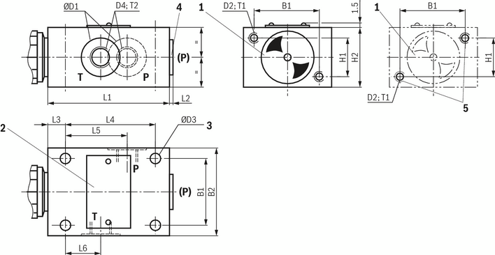
1 |
Adjustment type "S" (example) |
2 |
Name plate |
3 |
4 valve mounting bores |
4 |
Additional port (P), optional (e.g. for pressure measurement); not possible for NG10 and pressure rating >400 bar (= version "SO292"). Dimensions see dimensions D4, tightening torque see table below. |
5 |
Arrangement of the tapped holes with version "12" |
NG |
B1 |
B2 |
ØD1 |
D2 |
ØD3 |
D4 |
H1 |
H2 |
L1 |
L2 |
L3 |
L4 |
L5 |
L6 |
T1 |
T2 |
Weight (approx.) |
mm |
mm |
mm |
mm |
mm |
mm |
mm |
mm |
mm |
mm |
mm |
mm |
mm |
mm |
kg |
|||
| 6 | 45 | 60 | 25 | M6 | 6.6 | G1/4 | 25 | 40 | 80 | 4 | 15 | 55 | 40 | 20 | 10 | 12 | 1.5 |
| 8 | 60 | 80 | 28 | M8 | 9 | G3/8 | 40 | 60 | 100 | 4 | 20 | 70 | 48 | 21 | 15 | 12 | 3.7 |
| 10 | 60 | 80 | 34 | M8 | 9 | G1/2 | 40 | 60 | 100 | 4 | 20 | 70 | 48 | 21 | 15 | 14 | 3.7 |
| 15 | 70 | 100 | 42 | M8 | 9 | G3/4 | 50 | 70 | 135 | 4 | 20 | 100 | 65 | 34 | 18 | 16 | 6.4 |
| 20 | 70 | 100 | 47 | M8 | 9 | G1 | 50 | 70 | 135 | 5.5 | 20 | 100 | 65 | 34 | 18 | 18 | 6.4 |
| 25 | 100 | 130 | 56 | M10 | 11 | G1 1/4 | 60 | 90 | 180 | 5.5 | 25 | 130 | 85 | 35 | 20 | 20 | 13.9 |
| 30 | 100 | 130 | 65 | M10 | 11 | G1 1/2 | 60 | 90 | 180 | 5.5 | 25 | 130 | 85 | 35 | 20 | 22 | 13.9 |
NG |
ØD1 |
D2 |
D4 |
T2 |
mm |
mm |
|||
| 6 | 21 | 1/4"-20 UNC | 7/16"-20 UNF | 12 |
| 8 | 25 | 5/16"-18 UNC | 9/16"-18 UNF | 13 |
| 10 | 32 | 5/16"-18 UNC | 3/4"-16 UNF | 15 |
| 15 | 41 | 5/16"-18 UNC | 1 1/16"-12 UN | 20 |
| 20 | 49 | 5/16"-18 UNC | 1 5/16"-12 UN | 20 |
| 25 | 58 | 3/8"-16 UNC | 1 5/8"-12 UN | 20 |
| 30 | 70 | 3/8"-16 UNC | 1 7/8"-12 UN | 16 |
NG |
Tightening torque MA in Nm 1) |
|
Plug screw (4) |
Pipe fittings |
|
6 |
30 |
60 |
8 |
40 |
90 |
10 |
60 |
130 |
15 |
80 |
200 |
20 |
135 |
380 |
25 |
480 |
500 |
30 |
560 |
600 |
| 1) | The tightening torques are guidelines, referring to the maximum operating pressure and when using a manual torque wrench (tolerance ±10 %). |
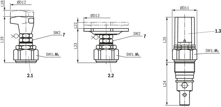
Dimensions in mm

1.1 |
Adjustment type "S” – Grub screw with hexagon and protective cap; internal hexagon (NG6 … NG20) |
1.2 |
Adjustment type "S” – Grub screw with hexagon and protective cap; external hexagon (NG30) |
1.3 |
Adjustment type "S” – Grub screw with hexagon and protective cap; version "J3" and "J5" |
2.1 |
Adjustment type “H” – rotary knob (NG6 … NG20) |
2.2 |
Adjustment type “H” – hand wheel (NG30) |
3 |
Adjustment type "A” – lockable rotary knob (NG6 … NG10; NG20 …100 bar) |
4 |
Type designation |
5 |
Marking (adjustment of the zero position after the valve has been screwed in; then fixing of the ring by horizontal shifting until it engages on the plug screw SW6). |
6 |
Lock nut, tightening torque MA = 10+5 Nm |
7 |
Space required to remove the key |
NG |
ØD11 |
ØD12 |
ØD13 |
L17 |
L18 |
L19 |
L20 |
L21 |
L22 |
L23 |
L24 |
L25 |
SW1 |
SW2 |
SW3 |
SW4 |
SW5 |
SW6 |
Weight (approx.) |
mm |
mm |
mm |
mm |
mm |
mm |
mm |
mm |
mm |
mm |
mm |
mm |
mm |
mm |
mm |
mm |
mm |
mm |
kg |
|
| 6 | 34 | 60 | - | 72 | 11 | 83 | 28 | 20 | - | - | 64.5 | 82.5 | 32 | 19 | 6 | - | 30 | 19 | 0.4 |
| 10 | 38 | 60 | - | 68 | 11 | 79 | 28 | 20 | - | - | 77 | 78.5 | 36 | 19 | 6 | - | 30 | 19 | 0.5 |
| 20 | 48 | 60 | - | 65 | 11 | 77 | 28 | 20 | - | - | 106 | 75 | 46 | 19 | 6 | - | 30 | 19 | 1 |
| 30 | 63 | - | 80 | 83 | - | - | - | - | 11 | 56 | 131 | 94.3 | 60 | 19 | - | 13 | - | 19 | 2.2 |
NG |
Pressure rating in bar |
||
Up to 200 |
Up to 400 |
Up to 630 |
|
6 |
50±5 |
80±5 |
‒ |
10 |
100±5 |
150±10 |
200±10 |
20 |
150±10 |
300±15 |
‒ |
30 |
350±20 |
500±30 |
‒ |
The tightening torques are guidelines with a friction coefficient μtotal = 0.12 and when using a manual torque wrench. |
|||
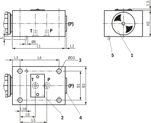
Dimensions in mm

| 1) | All seal ring in sertion faces are rounded and free of burrs; tolerance for all angles ± 0.5° |
1 |
Port P, at any place at the circumference or at the front side |
2 |
Port T, at any place at the circumference |
3 |
Depth of fit |
4 |
Minimum stability of the housing materials, see "Technical data". |
NG |
D14 |
ØD15 |
ØD16 |
ØD17 |
ØD18 |
ØD19 |
L26 |
L27 |
L28 |
L29 |
L30 |
L31 |
L32 |
α1 |
|||
mm |
mm |
mm |
mm |
mm |
mm |
mm |
mm |
mm |
mm |
mm |
mm |
mm |
mm |
° |
|||
| 6 | M28 x 1.5 | 25 | H9 | 6 | 15 | 24.9 | + 0.152 - 0.2 |
12 | 15 | 19 | 30 | 36 | 45 | 56.5 | ± 5.5 | 65 | 15 |
| 10 | M35 x 1.5 | 32 | H9 | 10 | 18.5 | 31.9 | + 0.162 - 0.2 |
15 | 18 | 23 | 35 | 41.5 | 52 | 67.5 | ± 7.5 | 80 | 15 |
| 20 | M45 x 1.5 | 40 | H9 | 20 | 24 | 39.9 | + 0.162 - 0.2 |
22 | 21 | 27 | 45 | 55 | 70 | 91.5 | ± 8.5 | 110 | 20 |
| 30 | M60 x 2 | 55 | H9 | 30 | 38.75 | 54.9 | + 0.174 - 0.2 |
34 | 23 | 29 | 45 | 63 | 84 | 113.5 | ± 11.5 | 140 | 20 |
Dimensions in mm

|
Required surface quality of the valve contact surface |
1 |
Adjustment type "S" (example) |
2 |
Name plate |
3 |
4 valve mounting bores |
4 |
Additional port (P), optional (e.g. for pressure measurement); not possible for NG10 and pressure rating > 400 bar (= version “SO292”). (Tightening torques see dimensional table) |
5 |
Locking pin (only with type-examination tested safety valves) |
NG |
B1 |
B2 |
ØD3 |
H2 |
L1 |
L2 |
L3 |
L4 |
L5 |
L6 |
L18 |
Port P |
Weight (approx.) |
mm |
mm |
mm |
mm |
mm |
mm |
mm |
mm |
mm |
mm |
mm |
kg |
||
| 6 | 45 | 60 | 6.6 | 40 | 80 | 4 | 15 | 55 | 40 | 20 | 15 | G1/4 | 1.5 |
| 10 | 60 | 80 | 9 | 60 | 100 | 4 | 20 | 70 | 45 | 21 | 15 | G1/2 | 3.7 |
| 20 | 70 | 100 | 9 | 70 | 135 | 5.5 | 20 | 100 | 65 | 34 | 15 | G3/4 | 6.4 |
| 30 | 100 | 130 | 11 | 90 | 180 | 5.5 | 25 | 130 | 85 | 35 | 15 | G1 1/4 | 13.9 |
NG |
Port P |
| 6 | 7/16"-20 UNF |
| 10 | 3/4"-16 UNF |
| 20 | 1 5/16"-12 UN |
| 30 | 1 7/8"-12 UN |
Size |
Quantity |
Hexagon socket head cap screws |
Material number |
6 |
4 |
ISO 4762 - M6 x 50 - 10.9-CM-Fe-ZnNi-5-Cn-T0-H-B (Friction coefficient μtotal = 0.09 … 0.14) Tightening torque MA = 12.5 Nm ±10 % |
R913048088 |
10 |
4 |
ISO 4762 - M8 x 70 - 10.9-FlZn/nc/480h/C Tightening torque MA = 28 Nm ± 10 % |
R913043410 |
20 |
4 |
ISO 4762 - M8 x 90 - 12.9-flZn/nc/480h/C Tightening torque MA = 28 Nm ± 10 % |
R913069227 |
30 |
4 |
ISO 4762 - M10 x 110 - 12.9-flZn/nc/480h/C Tightening torque MA = 56 Nm ±10 % |
R913059433 |
Notices:
For reasons of stability, exclusively the specified valve mounting screws shall be used.
As replacement, you can use screws specified according to DIN 912.
(Component series 1X, according to the Pressure Equipment Directive 2014/68/EU)
Dimensions in mm
1.3 |
Adjustment type "S" – hexagon with safety cap |
2.1 |
Adjustment type “H”, hand wheel |
2.2 |
Adjustment type “H” – rotary knob |
7 |
Lock nut, tightening torque MA = 10+5 Nm |
ØD11 |
ØD12 |
ØD13 |
L18 |
L19 |
L22 |
L23 |
L24 |
L25 |
SW1 |
SW2 |
Weight (approx.) |
mm |
mm |
mm |
mm |
mm |
mm |
mm |
mm |
mm |
mm |
mm |
kg |
| 34 | 60 | 40 | 11 | 83 | 11 | 63 | 64.5 | 80 | 32 | 19 | 0.4 |
| 38 | 60 | 40 | 11 | 97 | 11 | 59 | 78.5 | 76.5 | 36 | 19 | 0.5 |
| 48 | 60 | 40 | 11 | 77 | 11 | 57 | 107 | 72.5 | 46 | 19 | 1 |
| 63 | - | 80 | - | - | 11 | 87 | 134 | 93 | 60 | 19 | 2.2 |
NG6 |
NG10 |
NG20 |
NG30 |
|
Without corrosion protection |
2.1 |
2.1 |
2.1 |
2.2 |
Version "J3" and "J5" |
2.2 |
2.2 |
2.2 |
2.2 |
(Component series 1X, according to the Pressure Equipment Directive 2014/68/EU)
Dimensions in mm

NG |
B1 |
B2 |
H1 |
H2 |
ØD1H13 |
ØD2H13 |
R1 |
mm |
mm |
mm |
mm |
mm |
mm |
mm |
|
| 6 | 45 | 12.5 | 25 | 22.5 | 7 | 40 | 8 |
| 10 | 60 | 20.5 | 40 | 20.5 | 9 | 44 | 8 |
| 20 | 70 | 24 | 50 | 24 | 9 | 55 | 8 |
| 30 | 100 | 29.5 | 60 | 29.5 | 11 | 73 | 8 |
Notice:
With valves type DBDH.K….E, the hand wheel must be removed and reassembled before the front panel assembly of the screw-in cartridge valve.
Dimensions in mm
1 |
Adjustment type "S" (example) |
2 |
Name plate |
3 |
4 valve mounting bores |
4 |
Additional port (P), optional (e.g. for pressure measurement); not possible for NG10 and pressure rating >400 bar (= version "SO292"). Dimensions see dimensions D4, tightening torque see table below. |
5 |
Arrangement of the tapped holes with version "12" |
NG |
B1 |
B2 |
ØD1 |
D2 |
ØD3 |
D4 |
H1 |
H2 |
L1 |
L2 |
L3 |
L4 |
L5 |
L6 |
T1 |
T2 |
Weight (approx.) |
mm |
mm |
mm |
mm |
mm |
mm |
mm |
mm |
mm |
mm |
mm |
mm |
mm |
mm |
kg |
|||
| 6 | 45 | 60 | 25 | M6 | 6.6 | G1/4 | 25 | 40 | 80 | 4 | 15 | 55 | 40 | 20 | 10 | 12 | 1.5 |
| 8 | 60 | 80 | 28 | M8 | 9 | G3/8 | 40 | 60 | 100 | 4 | 20 | 70 | 48 | 21 | 15 | 12 | 3.7 |
| 10 | 60 | 80 | 34 | M8 | 9 | G1/2 | 40 | 60 | 100 | 4 | 20 | 70 | 48 | 21 | 15 | 14 | 3.7 |
| 15 | 70 | 100 | 42 | M8 | 9 | G3/4 | 50 | 70 | 135 | 4 | 20 | 100 | 65 | 34 | 18 | 16 | 6.4 |
| 20 | 70 | 100 | 47 | M8 | 9 | G1 | 50 | 70 | 135 | 5.5 | 20 | 100 | 65 | 34 | 18 | 18 | 6.4 |
| 25 | 100 | 130 | 56 | M10 | 11 | G1 1/4 | 60 | 90 | 180 | 5.5 | 25 | 130 | 85 | 35 | 20 | 20 | 13.9 |
| 30 | 100 | 130 | 65 | M10 | 11 | G1 1/2 | 60 | 90 | 180 | 5.5 | 25 | 130 | 85 | 35 | 20 | 22 | 13.9 |
NG |
ØD1 |
D2 |
D4 |
T2 |
mm |
mm |
|||
| 6 | 21 | 1/4"-20 UNC | 7/16"-20 UNF | 12 |
| 8 | 25 | 5/16"-18 UNC | 9/16"-18 UNF | 13 |
| 10 | 32 | 5/16"-18 UNC | 3/4"-16 UNF | 15 |
| 15 | 41 | 5/16"-18 UNC | 1 1/16"-12 UN | 20 |
| 20 | 49 | 5/16"-18 UNC | 1 5/16"-12 UN | 20 |
| 25 | 58 | 3/8"-16 UNC | 1 5/8"-12 UN | 20 |
| 30 | 70 | 3/8"-16 UNC | 1 7/8"-12 UN | 16 |
NG |
Tightening torque MA in Nm 1) |
|
Plug screw (4) |
Pipe fittings |
|
6 |
30 |
60 |
8 |
40 |
90 |
10 |
60 |
130 |
15 |
80 |
200 |
20 |
135 |
380 |
25 |
480 |
500 |
30 |
560 |
600 |
| 1) | The tightening torques are guidelines, referring to the maximum operating pressure and when using a manual torque wrench (tolerance ±10 %). |
Dimensions in mm
1.1 |
Adjustment type "S” – Grub screw with hexagon and protective cap; internal hexagon (NG6 … NG20) |
1.2 |
Adjustment type "S” – Grub screw with hexagon and protective cap; external hexagon (NG30) |
1.3 |
Adjustment type "S” – Grub screw with hexagon and protective cap; version "J3" and "J5" |
2.1 |
Adjustment type “H” – rotary knob (NG6 … NG20) |
2.2 |
Adjustment type “H” – hand wheel (NG30) |
3 |
Adjustment type "A” – lockable rotary knob (NG6 … NG10; NG20 …100 bar) |
4 |
Type designation |
5 |
Marking (adjustment of the zero position after the valve has been screwed in; then fixing of the ring by horizontal shifting until it engages on the plug screw SW6). |
6 |
Lock nut, tightening torque MA = 10+5 Nm |
7 |
Space required to remove the key |
NG |
ØD11 |
ØD12 |
ØD13 |
L17 |
L18 |
L19 |
L20 |
L21 |
L22 |
L23 |
L24 |
L25 |
SW1 |
SW2 |
SW3 |
SW4 |
SW5 |
SW6 |
Weight (approx.) |
mm |
mm |
mm |
mm |
mm |
mm |
mm |
mm |
mm |
mm |
mm |
mm |
mm |
mm |
mm |
mm |
mm |
mm |
kg |
|
| 6 | 34 | 60 | - | 72 | 11 | 83 | 28 | 20 | - | - | 64.5 | 82.5 | 32 | 19 | 6 | - | 30 | 19 | 0.4 |
| 10 | 38 | 60 | - | 68 | 11 | 79 | 28 | 20 | - | - | 77 | 78.5 | 36 | 19 | 6 | - | 30 | 19 | 0.5 |
| 20 | 48 | 60 | - | 65 | 11 | 77 | 28 | 20 | - | - | 106 | 75 | 46 | 19 | 6 | - | 30 | 19 | 1 |
| 30 | 63 | - | 80 | 83 | - | - | - | - | 11 | 56 | 131 | 94.3 | 60 | 19 | - | 13 | - | 19 | 2.2 |
NG |
Pressure rating in bar |
||
Up to 200 |
Up to 400 |
Up to 630 |
|
6 |
50±5 |
80±5 |
‒ |
10 |
100±5 |
150±10 |
200±10 |
20 |
150±10 |
300±15 |
‒ |
30 |
350±20 |
500±30 |
‒ |
The tightening torques are guidelines with a friction coefficient μtotal = 0.12 and when using a manual torque wrench. |
|||
Dimensions in mm
| 1) | All seal ring in sertion faces are rounded and free of burrs; tolerance for all angles ± 0.5° |
1 |
Port P, at any place at the circumference or at the front side |
2 |
Port T, at any place at the circumference |
3 |
Depth of fit |
4 |
Minimum stability of the housing materials, see "Technical data". |
NG |
D14 |
ØD15 |
ØD16 |
ØD17 |
ØD18 |
ØD19 |
L26 |
L27 |
L28 |
L29 |
L30 |
L31 |
L32 |
α1 |
|||
mm |
mm |
mm |
mm |
mm |
mm |
mm |
mm |
mm |
mm |
mm |
mm |
mm |
mm |
° |
|||
| 6 | M28 x 1.5 | 25 | H9 | 6 | 15 | 24.9 | + 0.152 - 0.2 |
12 | 15 | 19 | 30 | 36 | 45 | 56.5 | ± 5.5 | 65 | 15 |
| 10 | M35 x 1.5 | 32 | H9 | 10 | 18.5 | 31.9 | + 0.162 - 0.2 |
15 | 18 | 23 | 35 | 41.5 | 52 | 67.5 | ± 7.5 | 80 | 15 |
| 20 | M45 x 1.5 | 40 | H9 | 20 | 24 | 39.9 | + 0.162 - 0.2 |
22 | 21 | 27 | 45 | 55 | 70 | 91.5 | ± 8.5 | 110 | 20 |
| 30 | M60 x 2 | 55 | H9 | 30 | 38.75 | 54.9 | + 0.174 - 0.2 |
34 | 23 | 29 | 45 | 63 | 84 | 113.5 | ± 11.5 | 140 | 20 |
Dimensions in mm
|
|
Required surface quality of the valve contact surface |
1 |
Adjustment type "S" (example) |
2 |
Name plate |
3 |
4 valve mounting bores |
4 |
Additional port (P), optional (e.g. for pressure measurement); not possible for NG10 and pressure rating > 400 bar (= version “SO292”). (Tightening torques see dimensional table) |
5 |
Locking pin (only with type-examination tested safety valves) |
NG |
B1 |
B2 |
ØD3 |
H2 |
L1 |
L2 |
L3 |
L4 |
L5 |
L6 |
L18 |
Port P |
Weight (approx.) |
mm |
mm |
mm |
mm |
mm |
mm |
mm |
mm |
mm |
mm |
mm |
kg |
||
| 6 | 45 | 60 | 6.6 | 40 | 80 | 4 | 15 | 55 | 40 | 20 | 15 | G1/4 | 1.5 |
| 10 | 60 | 80 | 9 | 60 | 100 | 4 | 20 | 70 | 45 | 21 | 15 | G1/2 | 3.7 |
| 20 | 70 | 100 | 9 | 70 | 135 | 5.5 | 20 | 100 | 65 | 34 | 15 | G3/4 | 6.4 |
| 30 | 100 | 130 | 11 | 90 | 180 | 5.5 | 25 | 130 | 85 | 35 | 15 | G1 1/4 | 13.9 |
NG |
Port P |
| 6 | 7/16"-20 UNF |
| 10 | 3/4"-16 UNF |
| 20 | 1 5/16"-12 UN |
| 30 | 1 7/8"-12 UN |
Size |
Quantity |
Hexagon socket head cap screws |
Material number |
6 |
4 |
ISO 4762 - M6 x 50 - 10.9-CM-Fe-ZnNi-5-Cn-T0-H-B (Friction coefficient μtotal = 0.09 … 0.14) Tightening torque MA = 12.5 Nm ±10 % |
R913048088 |
10 |
4 |
ISO 4762 - M8 x 70 - 10.9-FlZn/nc/480h/C Tightening torque MA = 28 Nm ± 10 % |
R913043410 |
20 |
4 |
ISO 4762 - M8 x 90 - 12.9-flZn/nc/480h/C Tightening torque MA = 28 Nm ± 10 % |
R913069227 |
30 |
4 |
ISO 4762 - M10 x 110 - 12.9-flZn/nc/480h/C Tightening torque MA = 56 Nm ±10 % |
R913059433 |
Notices:
For reasons of stability, exclusively the specified valve mounting screws shall be used.
As replacement, you can use screws specified according to DIN 912.
(Component series 1X, according to the Pressure Equipment Directive 2014/68/EU)
Dimensions in mm
1.3 |
Adjustment type "S" – hexagon with safety cap |
2.1 |
Adjustment type “H”, hand wheel |
2.2 |
Adjustment type “H” – rotary knob |
7 |
Lock nut, tightening torque MA = 10+5 Nm |
ØD11 |
ØD12 |
ØD13 |
L18 |
L19 |
L22 |
L23 |
L24 |
L25 |
SW1 |
SW2 |
Weight (approx.) |
mm |
mm |
mm |
mm |
mm |
mm |
mm |
mm |
mm |
mm |
mm |
kg |
| 34 | 60 | 40 | 11 | 83 | 11 | 63 | 64.5 | 80 | 32 | 19 | 0.4 |
| 38 | 60 | 40 | 11 | 97 | 11 | 59 | 78.5 | 76.5 | 36 | 19 | 0.5 |
| 48 | 60 | 40 | 11 | 77 | 11 | 57 | 107 | 72.5 | 46 | 19 | 1 |
| 63 | - | 80 | - | - | 11 | 87 | 134 | 93 | 60 | 19 | 2.2 |
NG6 |
NG10 |
NG20 |
NG30 |
|
Without corrosion protection |
2.1 |
2.1 |
2.1 |
2.2 |
Version "J3" and "J5" |
2.2 |
2.2 |
2.2 |
2.2 |
(Component series 1X, according to the Pressure Equipment Directive 2014/68/EU)
Dimensions in mm
NG |
B1 |
B2 |
H1 |
H2 |
ØD1H13 |
ØD2H13 |
R1 |
mm |
mm |
mm |
mm |
mm |
mm |
mm |
|
| 6 | 45 | 12.5 | 25 | 22.5 | 7 | 40 | 8 |
| 10 | 60 | 20.5 | 40 | 20.5 | 9 | 44 | 8 |
| 20 | 70 | 24 | 50 | 24 | 9 | 55 | 8 |
| 30 | 100 | 29.5 | 60 | 29.5 | 11 | 73 | 8 |
Notice:
With valves type DBDH.K….E, the hand wheel must be removed and reassembled before the front panel assembly of the screw-in cartridge valve.


