| Availability: | |
|---|---|
| Quantity: | |

A A10F E 10 /52L-VCH16N002
Rexroth
R902449895
Space-saving construction due to recessed mounting flange
Approved for high speeds
Long service life
High power density
Low operating noise
Optional with integrated anti-cavitation valve, e.g. for fan drives
Optional with speed sensor
Swashplate design
Space-saving construction due to recessed mounting flange
Approved for high speeds
Long service life
High power density
Low operating noise
Optional with integrated anti-cavitation valve, e.g. for fan drives
Optional with speed sensor
Swashplate design

| 1) | Only necessary in conjunction with valve configuration "2" (integrated anti cavitation valve) |
| 2) | Drive shaft R with flange C on sizes 10 … 18 in preparation |
| 1) | Only necessary in conjunction with valve configuration "2" (integrated anti cavitation valve) |
| 2) | Drive shaft R with flange C on sizes 10 … 18 in preparation |
Size | 10 | 11 | 14 | 16 | 18 | 23 | 28 | 37 | 45 | 58 | 63 | |||
Displacement | Vg | cm³ | 10.6 | 11.5 | 14.1 | 16.1 | 18 | 23.5 | 28.5 | 36.7 | 44.5 | 58 | 63.1 | |
Nominal pressure | pnom | bar | 280 | 280 | 280 | 280 | 280 | 280 | 280 | 280 | 280 | 280 | 280 | |
Maximum pressure | pmax | bar | 350 | 350 | 350 | 350 | 350 | 350 | 350 | 350 | 350 | 350 | 350 | |
Maximum speed 1) | nnom | rpm | 5000 | 4200 | 4200 | 4200 | 4200 | 4900 | 4700 | 4200 | 4000 | 3600 | 3400 | |
Inlet flow | at nnom | qV | l/min | 53 | 48 | 59 | 68 | 76 | 115 | 134 | 154 | 178 | 209 | 215 |
Power | at nnom and pnom | P | kW | 24.7 | 22.5 | 27.6 | 31.6 | 35.3 | 53.6 | 62.5 | 71.8 | 83.1 | 97.4 | 100.1 |
Starting torque | at nnom and pnom | M0 | Nm | 37.5 | 30 | 45 | 53 | 67.5 | 75 | 105 | 125 | 170 | 205 | 230 |
Torque | at pnom | M | Nm | 47 | 51 | 63 | 72 | 80 | 105 | 127 | 163 | 198 | 258 | 281 |
Rotary stiffness | Drive shaft R | c | kNm/rad | 14.835 | 28.478 | 28.478 | 46.859 | 46.859 | 80.59 | 80.59 | ||||
Drive shaft W | c | kNm/rad | 38.489 | 34.489 | 60.907 | 60.907 | ||||||||
Drive shaft C | c | kNm/rad | 15.084 | 18.662 | 18.662 | 18.662 | 18.662 | 30.017 | 30.017 | 46.546 | 46.546 | 87.667 | 87.667 | |
Moment of inertia for rotary group | JTW | kg·m² | 0.0006 | 0.00093 | 0.00093 | 0.00093 | 0.00093 | 0.0017 | 0.0017 | 0.0033 | 0.0033 | 0.0056 | 0.0056 | |
Maximum angular acceleration | ɑ | rad/s² | 8000 | 6800 | 6800 | 6800 | 6800 | 5500 | 5500 | 4000 | 4000 | 3300 | 3300 | |
Case volume | V | l | 0.1 | 0.15 | 0.15 | 0.15 | 0.15 | 0.6 | 0.6 | 0.7 | 0.7 | 0.8 | 0.8 | |
Weight (approx.) | m | kg | 5 | 6.5 | 6.5 | 6.5 | 6.5 | 12 | 12 | 17 | 17 | 22 | 22 | |
| 1) | At least 18 bar required at low pressure side |
The values in the table are theoretical values, without consideration of efficiencies and tolerances. The values are rounded.
Exceeding the maximum or falling below the minimum permissible values can lead to a loss of function, a reduction in operational service life or total destruction of the axial piston unit. We recommend testing the loads by means of experiment or calculation / simulation and comparison with the permissible values.
Determining the operating characteristics | ||
Inlet flow |  | [l/min] |
Rotational speed |  | [rpm] |
Torque |  | [Nm] |
Power |  | [kW] |
Key | |
Vg | Displacement per revolution [cm3] |
Δp | Differential pressure [bar] |
n | Rotational speed [rpm] |
ηv | Volumetric efficiency |
ηhm | Hydraulic-mechanical efficiency |
ηt | Total efficiency (ηt = ηv • ηhm) |
The axial piston unit is designed for operation with mineral oil HLP according to DIN 51524.
Application instructions and requirements for hydraulic fluids should be taken from the following data sheets before the start of project planning:
For operation with environmentally acceptable fluids please consult us.
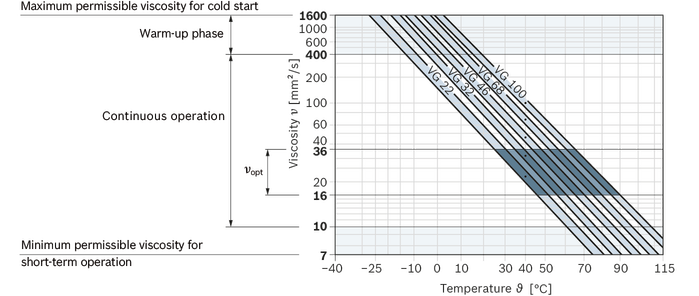
Viscosity | Shaft | Temperature1) | Comment | |
Cold start | νmax ≤ 1600 mm²/s | NBR2) | ϑSt ≥ -40 °C | t ≤ 1 min, without load (p ≤ 30 bar), n ≤ 1000 rpm, |
FKM | ϑSt ≥ -25 °C | |||
Warm-up phase | ν = 400 … 1600 mm²/s | t ≤ 15 min, p ≤ 0.7 • pnom and n ≤ 0.5 • nnom | ||
Continuous operation | ν = 10 … 400 mm²/s3) | NBR2) | ϑ ≤ +78 °C | measured at port L |
FKM | ϑ ≤ +103 °C | |||
νopt = 16 … 36 mm²/s | range of optimum operating viscosity and efficiency | |||
Short-term operation | νmin = 7 … 10 mm²/s | NBR2) | ϑ ≤ +78 °C | t ≤ 3 min, p ≤ 0.3 • pnom measured at port L |
FKM | ϑ ≤ +103 °C |
| 1) | If the specified temperatures cannot be maintained due to extreme operating parameters, please contact us. |
| 2) | Special version, please contact us. |
| 3) | Equates e.g. with the VG 46 a temperature range of +5 °C to +85 °C (see selection diagram) |
Bosch Rexroth evaluates hydraulic fluids on the basis of the Fluid Rating according to the technical data sheet 90235.
Hydraulic fluids with positive evaluation in the Fluid Rating are provided in the following technical data sheet:
The hydraulic fluid should be selected so that the operating viscosity in the operating temperature range is within the optimum range (νopt; see selection diagram).
Finer filtration improves the cleanliness level of the hydraulic fluid, which increases the service life of the axial piston unit.
A cleanliness level of at least 20/18/15 is to be maintained according to ISO 4406.
At a hydraulic fluid viscosity of less than 10 mm²/s (e.g. due to high temperatures in short-term operation) at the drain port, a cleanliness level of at least 19/17/14 according to ISO 4406 is required.
For example, the viscosity is 10 mm²/s at:
HLP 32 a temperature of 73°C
HLP 46 a temperature of 85°C
Pressure at working port A or B | Definition | ||
Nominal pressure | pnom | see table of values | The nominal pressure corresponds to the maximum design pressure. |
Maximum pressure | pmax | see table of values | The maximum pressure corresponds to the maximum operating pressure within the single operating period. The sum of the single operating periods must not exceed the total operating period. |
Single operating period | 2.5 s | ||
Total operating period | 300 h | ||
Minimum pressure (high-pressure side) | pHP min | 10 bar | Minimum pressure on high- or low-pressure side (port A or B) required to prevent damage to the axial piston unit. |
Minimum pressure (low-pressure side) | pLP min | see diagram "Permissible rotational speed in relation to outlet pressure" | |
Rate of pressure change | Definition | ||
Rate of pressure change | RA max | 16000 bar/s | Maximum permissible rate of pressure build-up and reduction during a pressure change over the entire pressure range. |
Case pressure at port L | Definition | ||
Motor operation mode | pL max | 4 bar absolute | Maximum permissible case pressure measured at port L or L1 |
Pump operating mode | pL max | 2 bar absolute | |
Working pressure range valid when using hydraulic fluids based on mineral oils. Values for other hydraulic fluids, please contact us.


| 1) | Total operating period = t1 + t2 + ... + tn |

Direction of rotation, viewed on drive shaft | |
clockwise | counter-clockwise |
A to B | B to A |
Size | 10 | 11 | 14 | 16 | 18 | 23 | 28 | 37 | 45 | 58 | 63 | ||||
Splined shaft | Code | R | R | R | R | R | R, W | R, W | R, W | R, W | R, W | R, W | |||
Tapered shaft | Code | C | C | C | C | C | C | C | C | C | C | C | |||
Maximum radial force |  |  | Fq max | N | 250 | 350 | 350 | 350 | 350 | 1200 | 1200 | 1500 | 1500 | 1700 | 1700 |
Maximum axial force |  | ± Fax max | N | 400 | 700 | 700 | 700 | 700 | |||||||
Size | 10 | 11 | 14 | 16 | 18 | 23 | 28 | 37 | 45 | 58 | 63 | |||
Displacement | Vg | cm³ | 10.6 | 11.5 | 14.1 | 16.1 | 18 | 23.5 | 28.5 | 36.7 | 44.5 | 58 | 63.1 | |
Nominal pressure | pnom | bar | 280 | 280 | 280 | 280 | 280 | 280 | 280 | 280 | 280 | 280 | 280 | |
Maximum pressure | pmax | bar | 350 | 350 | 350 | 350 | 350 | 350 | 350 | 350 | 350 | 350 | 350 | |
Maximum speed 1) | nnom | rpm | 5000 | 4200 | 4200 | 4200 | 4200 | 4900 | 4700 | 4200 | 4000 | 3600 | 3400 | |
Inlet flow | at nnom | qV | l/min | 53 | 48 | 59 | 68 | 76 | 115 | 134 | 154 | 178 | 209 | 215 |
Power | at nnom and pnom | P | kW | 24.7 | 22.5 | 27.6 | 31.6 | 35.3 | 53.6 | 62.5 | 71.8 | 83.1 | 97.4 | 100.1 |
Starting torque | at nnom and pnom | M0 | Nm | 37.5 | 30 | 45 | 53 | 67.5 | 75 | 105 | 125 | 170 | 205 | 230 |
Torque | at pnom | M | Nm | 47 | 51 | 63 | 72 | 80 | 105 | 127 | 163 | 198 | 258 | 281 |
Rotary stiffness | Drive shaft R | c | kNm/rad | 14.835 | 28.478 | 28.478 | 46.859 | 46.859 | 80.59 | 80.59 | ||||
Drive shaft W | c | kNm/rad | 38.489 | 34.489 | 60.907 | 60.907 | ||||||||
Drive shaft C | c | kNm/rad | 15.084 | 18.662 | 18.662 | 18.662 | 18.662 | 30.017 | 30.017 | 46.546 | 46.546 | 87.667 | 87.667 | |
Moment of inertia for rotary group | JTW | kg·m² | 0.0006 | 0.00093 | 0.00093 | 0.00093 | 0.00093 | 0.0017 | 0.0017 | 0.0033 | 0.0033 | 0.0056 | 0.0056 | |
Maximum angular acceleration | ɑ | rad/s² | 8000 | 6800 | 6800 | 6800 | 6800 | 5500 | 5500 | 4000 | 4000 | 3300 | 3300 | |
Case volume | V | l | 0.1 | 0.15 | 0.15 | 0.15 | 0.15 | 0.6 | 0.6 | 0.7 | 0.7 | 0.8 | 0.8 | |
Weight (approx.) | m | kg | 5 | 6.5 | 6.5 | 6.5 | 6.5 | 12 | 12 | 17 | 17 | 22 | 22 | |
| 1) | At least 18 bar required at low pressure side |
The values in the table are theoretical values, without consideration of efficiencies and tolerances. The values are rounded.
Exceeding the maximum or falling below the minimum permissible values can lead to a loss of function, a reduction in operational service life or total destruction of the axial piston unit. We recommend testing the loads by means of experiment or calculation / simulation and comparison with the permissible values.
Determining the operating characteristics | ||
Inlet flow | | [l/min] |
Rotational speed | | [rpm] |
Torque | | [Nm] |
Power | | [kW] |
Key | |
Vg | Displacement per revolution [cm3] |
Δp | Differential pressure [bar] |
n | Rotational speed [rpm] |
ηv | Volumetric efficiency |
ηhm | Hydraulic-mechanical efficiency |
ηt | Total efficiency (ηt = ηv • ηhm) |
The axial piston unit is designed for operation with mineral oil HLP according to DIN 51524.
Application instructions and requirements for hydraulic fluids should be taken from the following data sheets before the start of project planning:
For operation with environmentally acceptable fluids please consult us.
Viscosity | Shaft | Temperature1) | Comment | |
Cold start | νmax ≤ 1600 mm²/s | NBR2) | ϑSt ≥ -40 °C | t ≤ 1 min, without load (p ≤ 30 bar), n ≤ 1000 rpm, |
FKM | ϑSt ≥ -25 °C | |||
Warm-up phase | ν = 400 … 1600 mm²/s | t ≤ 15 min, p ≤ 0.7 • pnom and n ≤ 0.5 • nnom | ||
Continuous operation | ν = 10 … 400 mm²/s3) | NBR2) | ϑ ≤ +78 °C | measured at port L |
FKM | ϑ ≤ +103 °C | |||
νopt = 16 … 36 mm²/s | range of optimum operating viscosity and efficiency | |||
Short-term operation | νmin = 7 … 10 mm²/s | NBR2) | ϑ ≤ +78 °C | t ≤ 3 min, p ≤ 0.3 • pnom measured at port L |
FKM | ϑ ≤ +103 °C |
| 1) | If the specified temperatures cannot be maintained due to extreme operating parameters, please contact us. |
| 2) | Special version, please contact us. |
| 3) | Equates e.g. with the VG 46 a temperature range of +5 °C to +85 °C (see selection diagram) |
Bosch Rexroth evaluates hydraulic fluids on the basis of the Fluid Rating according to the technical data sheet 90235.
Hydraulic fluids with positive evaluation in the Fluid Rating are provided in the following technical data sheet:
The hydraulic fluid should be selected so that the operating viscosity in the operating temperature range is within the optimum range (νopt; see selection diagram).
Finer filtration improves the cleanliness level of the hydraulic fluid, which increases the service life of the axial piston unit.
A cleanliness level of at least 20/18/15 is to be maintained according to ISO 4406.
At a hydraulic fluid viscosity of less than 10 mm²/s (e.g. due to high temperatures in short-term operation) at the drain port, a cleanliness level of at least 19/17/14 according to ISO 4406 is required.
For example, the viscosity is 10 mm²/s at:
HLP 32 a temperature of 73°C
HLP 46 a temperature of 85°C
Pressure at working port A or B | Definition | ||
Nominal pressure | pnom | see table of values | The nominal pressure corresponds to the maximum design pressure. |
Maximum pressure | pmax | see table of values | The maximum pressure corresponds to the maximum operating pressure within the single operating period. The sum of the single operating periods must not exceed the total operating period. |
Single operating period | 2.5 s | ||
Total operating period | 300 h | ||
Minimum pressure (high-pressure side) | pHP min | 10 bar | Minimum pressure on high- or low-pressure side (port A or B) required to prevent damage to the axial piston unit. |
Minimum pressure (low-pressure side) | pLP min | see diagram "Permissible rotational speed in relation to outlet pressure" | |
Rate of pressure change | Definition | ||
Rate of pressure change | RA max | 16000 bar/s | Maximum permissible rate of pressure build-up and reduction during a pressure change over the entire pressure range. |
Case pressure at port L | Definition | ||
Motor operation mode | pL max | 4 bar absolute | Maximum permissible case pressure measured at port L or L1 |
Pump operating mode | pL max | 2 bar absolute | |
Working pressure range valid when using hydraulic fluids based on mineral oils. Values for other hydraulic fluids, please contact us.
| 1) | Total operating period = t1 + t2 + ... + tn |
Direction of rotation, viewed on drive shaft | |
clockwise | counter-clockwise |
A to B | B to A |
Size | 10 | 11 | 14 | 16 | 18 | 23 | 28 | 37 | 45 | 58 | 63 | ||||
Splined shaft | Code | R | R | R | R | R | R, W | R, W | R, W | R, W | R, W | R, W | |||
Tapered shaft | Code | C | C | C | C | C | C | C | C | C | C | C | |||
Maximum radial force | | | Fq max | N | 250 | 350 | 350 | 350 | 350 | 1200 | 1200 | 1500 | 1500 | 1700 | 1700 |
Maximum axial force | | ± Fax max | N | 400 | 700 | 700 | 700 | 700 | |||||||

| 1) | Flange ISO 3019-1 |

Size | 10 | ||
A, B | Working port | Size | M18 × 15; 17 mm deep |
Standard | DIN 3852 | ||
State on delivery | With protective cover (must be connected) | ||
L | Drain port | Size | M14 × 15; 13 mm deep |
Standard | DIN 3852 | ||
State on delivery | With protective cover (must be connected) | ||


| 1) | Flange ISO 3019-1 |

| 1) | Involute spline according to ANSI B92.1a, 30° pressure angle, flat root, side fit, tolerance class 5 |
Mounting flange | N1 | N2 | N3 |
H | 126.6 | 144.2 | 19 |
C | ‒ | 151.8 | 24 |
Size | 11 | 14 | 16 | 18 | ||
A, B | Working port | Size | M18 × 15; 12 mm deep | |||
Standard | DIN 3852 | |||||
State on delivery | With protective cover (must be connected) | |||||
L | Drain port | Size | M14 × 15; 12 mm deep | |||
Standard | DIN 3852 | |||||
State on delivery 1) | With protective cover (observe installation instructions) | |||||
L1 | Drain port | Size | M14 × 15; 12 mm deep | |||
Standard | DIN 3852 | |||||
State on delivery 1) | Plugged (observe installation instructions) | |||||
| 1) | Unless otherwise specified. Other layouts on request. |


| 1) | Involute spline according to ANSI B92.1a, 30° pressure angle, flat root, side fit, tolerance class 5 |
Size | 23 | 28 | ||
A, B | Working port | Size | 3/4 in | |
Standard | Dimensions according to SAE J518 | |||
Fastening thread 1) | M10 × 15; 17 mm deep | |||
State on delivery | With protective cover (must be connected) | |||
A, B | Working port | Size | M27 × 2; 16 mm deep | |
Standard | DIN 3852 | |||
State on delivery | With protective cover (must be connected) | |||
L | Drain port | Size | 3/4-16 UNF-2B; 11 mm deep | |
Standard 2) | ISO 11926 | |||
State on delivery 3) | With protective cover (observe installation instructions) | |||
L1 | Drain port | Size | 3/4-16 UNF-2B; 11 mm deep | |
Standard 2) | ISO 11926 | |||
State on delivery 3) | Plugged (observe installation instructions) | |||
| 1) | Thread according to DIN 13 |
| 2) | The spot face can be deeper than specified in the appropriate standard. |
| 3) | Unless otherwise specified. Other layouts on request. |


| 1) | Involute spline according to ANSI B92.1a, 30° pressure angle, flat root, side fit, tolerance class 5 |

Size | 37 | 45 | ||
A, B | Working port | Size | 3/4 in | |
Standard | Dimensions according to SAE J518 | |||
Fastening thread 1) | M10 × 15; 17 mm deep | |||
State on delivery | With protective cover (must be connected) | |||
A, B | Working port | Size | M27 × 2; 16 mm deep | |
Standard | DIN 3852 | |||
State on delivery | With protective cover (must be connected) | |||
L | Drain port | Size | 7/8-14 UNF-2B; 13 mm deep | |
Standard 2) | ISO 11926 | |||
State on delivery 3) | With protective cover (observe installation instructions) | |||
L1 | Drain port | Size | 7/8-14 UNF-2B; 13 mm deep | |
Standard 2) | ISO 11926 | |||
State on delivery 3) | Plugged (observe installation instructions) | |||
| 1) | Thread according to DIN 13 |
| 2) | The spot face can be deeper than specified in the appropriate standard. |
| 3) | Unless otherwise specified. Other layouts on request. |


| 1) | Involute spline according to ANSI B92.1a, 30° pressure angle, flat root, side fit, tolerance class 5 |

Size | 58 | 63 | ||
A, B | Working port | Size | 3/4 in | |
Standard | Dimensions according to SAE J518 | |||
Fastening thread 1) | M10 × 15; 17 mm deep | |||
State on delivery | With protective cover (must be connected) | |||
A, B | Working port | Size | M27 × 2; 16 mm deep | |
Standard | DIN 3852 | |||
State on delivery | With protective cover (must be connected) | |||
L | Drain port | Size | 7/8-14 UNF-2B; 13 mm deep | |
Standard 2) | ISO 11926 | |||
State on delivery 3) | With protective cover (observe installation instructions) | |||
L1 | Drain port | Size | 7/8-14 UNF-2B; 13 mm deep | |
Standard 2) | ISO 11926 | |||
State on delivery 3) | Plugged (observe installation instructions) | |||
| 1) | Thread according to DIN 13 |
| 2) | The spot face can be deeper than specified in the appropriate standard. |
| 3) | Unless otherwise specified. Other layouts on request. |
| 1) | Flange ISO 3019-1 |
Size | 10 | ||
A, B | Working port | Size | M18 × 15; 17 mm deep |
Standard | DIN 3852 | ||
State on delivery | With protective cover (must be connected) | ||
L | Drain port | Size | M14 × 15; 13 mm deep |
Standard | DIN 3852 | ||
State on delivery | With protective cover (must be connected) | ||
| 1) | Flange ISO 3019-1 |
| 1) | Involute spline according to ANSI B92.1a, 30° pressure angle, flat root, side fit, tolerance class 5 |
Mounting flange | N1 | N2 | N3 |
H | 126.6 | 144.2 | 19 |
C | ‒ | 151.8 | 24 |
Size | 11 | 14 | 16 | 18 | ||
A, B | Working port | Size | M18 × 15; 12 mm deep | |||
Standard | DIN 3852 | |||||
State on delivery | With protective cover (must be connected) | |||||
L | Drain port | Size | M14 × 15; 12 mm deep | |||
Standard | DIN 3852 | |||||
State on delivery 1) | With protective cover (observe installation instructions) | |||||
L1 | Drain port | Size | M14 × 15; 12 mm deep | |||
Standard | DIN 3852 | |||||
State on delivery 1) | Plugged (observe installation instructions) | |||||
| 1) | Unless otherwise specified. Other layouts on request. |
| 1) | Involute spline according to ANSI B92.1a, 30° pressure angle, flat root, side fit, tolerance class 5 |
Size | 23 | 28 | ||
A, B | Working port | Size | 3/4 in | |
Standard | Dimensions according to SAE J518 | |||
Fastening thread 1) | M10 × 15; 17 mm deep | |||
State on delivery | With protective cover (must be connected) | |||
A, B | Working port | Size | M27 × 2; 16 mm deep | |
Standard | DIN 3852 | |||
State on delivery | With protective cover (must be connected) | |||
L | Drain port | Size | 3/4-16 UNF-2B; 11 mm deep | |
Standard 2) | ISO 11926 | |||
State on delivery 3) | With protective cover (observe installation instructions) | |||
L1 | Drain port | Size | 3/4-16 UNF-2B; 11 mm deep | |
Standard 2) | ISO 11926 | |||
State on delivery 3) | Plugged (observe installation instructions) | |||
| 1) | Thread according to DIN 13 |
| 2) | The spot face can be deeper than specified in the appropriate standard. |
| 3) | Unless otherwise specified. Other layouts on request. |
| 1) | Involute spline according to ANSI B92.1a, 30° pressure angle, flat root, side fit, tolerance class 5 |
Size | 37 | 45 | ||
A, B | Working port | Size | 3/4 in | |
Standard | Dimensions according to SAE J518 | |||
Fastening thread 1) | M10 × 15; 17 mm deep | |||
State on delivery | With protective cover (must be connected) | |||
A, B | Working port | Size | M27 × 2; 16 mm deep | |
Standard | DIN 3852 | |||
State on delivery | With protective cover (must be connected) | |||
L | Drain port | Size | 7/8-14 UNF-2B; 13 mm deep | |
Standard 2) | ISO 11926 | |||
State on delivery 3) | With protective cover (observe installation instructions) | |||
L1 | Drain port | Size | 7/8-14 UNF-2B; 13 mm deep | |
Standard 2) | ISO 11926 | |||
State on delivery 3) | Plugged (observe installation instructions) | |||
| 1) | Thread according to DIN 13 |
| 2) | The spot face can be deeper than specified in the appropriate standard. |
| 3) | Unless otherwise specified. Other layouts on request. |
| 1) | Involute spline according to ANSI B92.1a, 30° pressure angle, flat root, side fit, tolerance class 5 |
Size | 58 | 63 | ||
A, B | Working port | Size | 3/4 in | |
Standard | Dimensions according to SAE J518 | |||
Fastening thread 1) | M10 × 15; 17 mm deep | |||
State on delivery | With protective cover (must be connected) | |||
A, B | Working port | Size | M27 × 2; 16 mm deep | |
Standard | DIN 3852 | |||
State on delivery | With protective cover (must be connected) | |||
L | Drain port | Size | 7/8-14 UNF-2B; 13 mm deep | |
Standard 2) | ISO 11926 | |||
State on delivery 3) | With protective cover (observe installation instructions) | |||
L1 | Drain port | Size | 7/8-14 UNF-2B; 13 mm deep | |
Standard 2) | ISO 11926 | |||
State on delivery 3) | Plugged (observe installation instructions) | |||
| 1) | Thread according to DIN 13 |
| 2) | The spot face can be deeper than specified in the appropriate standard. |
| 3) | Unless otherwise specified. Other layouts on request. |
During commissioning and operation, the axial piston unit must be filled with hydraulic fluid and air bled. This must also be observed following a relatively long standstill as the axial piston unit may drain back to the reservoir via the hydraulic lines.
The case drain fluid in the housing must be directed to the reservoir via the highest available drain port (L, L1).
If a shared drain line is used for several units, make sure that the respective case pressure is not exceeded. The shared drain line must be dimensioned to ensure that the maximum permissible case pressure of all connected units is not exceeded in any operating conditions, specifically on cold start. If this is not possible, separate reservoir lines must be laid as required.
To achieve favorable noise values, all connecting lines should be decoupled by using elastic elements and above-reservoir installation is to be avoided.
In all operating conditions, the drain line must flow into the reservoir below the minimum fluid level.
See the following examples 1 to 4.
Further installation positions are possible upon request. Recommended installation position: 1 and 2.
Below-tank installation is at hand if the axial piston unit is installed below the minimum liquid level outside the tank.

Installation position | Air bleeding | Filling |
1 | ‒ | L1 |
2 | ‒ | L |
Above-reservoir installation means that the axial piston unit is installed above the minimum fluid level of the reservoir.

Installation position | Air bleeding | Filling |
3 | F | L1 (F) |
4 | F | L (F) |
Key | |
F | Filling / Air bleeding |
L, L2 | Drain port |
SB | Baffle (baffle plate) |
A, B | Working port |
Connection F is part of the external piping and must be provided on the customer side to simplify the filling and bleeding.
The axial piston unit is designed to be used in open and closed circuits.
The project planning, installation and commissioning of the axial piston unit require the involvement of qualified skilled personnel.
Before using the axial piston unit, please read the corresponding instruction manual completely and thoroughly. If necessary, request it from Bosch Rexroth.
Before finalizing your design, request a binding installation drawing.
The specified datas and notes must be observed.
Preservation: Our axial piston units are supplied as standard with preservative protection for a maximum of 12 months. If longer preservative protection is required (maximum 24 months), please specify this in plain text when placing your order. The preservation times are valid under optimal storage conditions. Details of these conditions can be found in the data sheet 90312 or the instruction manual.
A pressure relief valve is to be provided in the hydraulic system.
Observe the instructions in the instruction manual regarding tightening torques of connection threads and other threaded joints used.
The notes in the instruction manual on tightening torques of the port threads and other screw joints must be observed.
The ports and fastening threads are designed for the permissible maximum pressure pmax (see instruction manual). The machine or system manufacturer must ensure that the connecting elements and lines correspond to the specified operating conditions (pressure, flow, hydraulic fluid, temperature) with the necessary safety factors.
The working ports and function ports are designated only to accommodate hydraulic lines.
During commissioning and operation, the axial piston unit must be filled with hydraulic fluid and air bled. This must also be observed following a relatively long standstill as the axial piston unit may drain back to the reservoir via the hydraulic lines.
The case drain fluid in the housing must be directed to the reservoir via the highest available drain port (L, L1).
If a shared drain line is used for several units, make sure that the respective case pressure is not exceeded. The shared drain line must be dimensioned to ensure that the maximum permissible case pressure of all connected units is not exceeded in any operating conditions, specifically on cold start. If this is not possible, separate reservoir lines must be laid as required.
To achieve favorable noise values, all connecting lines should be decoupled by using elastic elements and above-reservoir installation is to be avoided.
In all operating conditions, the drain line must flow into the reservoir below the minimum fluid level.
See the following examples 1 to 4.
Further installation positions are possible upon request. Recommended installation position: 1 and 2.
Below-tank installation is at hand if the axial piston unit is installed below the minimum liquid level outside the tank.
Installation position | Air bleeding | Filling |
1 | ‒ | L1 |
2 | ‒ | L |
Above-reservoir installation means that the axial piston unit is installed above the minimum fluid level of the reservoir.
Installation position | Air bleeding | Filling |
3 | F | L1 (F) |
4 | F | L (F) |
Key | |
F | Filling / Air bleeding |
L, L2 | Drain port |
SB | Baffle (baffle plate) |
A, B | Working port |
Connection F is part of the external piping and must be provided on the customer side to simplify the filling and bleeding.
The axial piston unit is designed to be used in open and closed circuits.
The project planning, installation and commissioning of the axial piston unit require the involvement of qualified skilled personnel.
Before using the axial piston unit, please read the corresponding instruction manual completely and thoroughly. If necessary, request it from Bosch Rexroth.
Before finalizing your design, request a binding installation drawing.
The specified datas and notes must be observed.
Preservation: Our axial piston units are supplied as standard with preservative protection for a maximum of 12 months. If longer preservative protection is required (maximum 24 months), please specify this in plain text when placing your order. The preservation times are valid under optimal storage conditions. Details of these conditions can be found in the data sheet 90312 or the instruction manual.
A pressure relief valve is to be provided in the hydraulic system.
Observe the instructions in the instruction manual regarding tightening torques of connection threads and other threaded joints used.
The notes in the instruction manual on tightening torques of the port threads and other screw joints must be observed.
The ports and fastening threads are designed for the permissible maximum pressure pmax (see instruction manual). The machine or system manufacturer must ensure that the connecting elements and lines correspond to the specified operating conditions (pressure, flow, hydraulic fluid, temperature) with the necessary safety factors.
The working ports and function ports are designated only to accommodate hydraulic lines.


