| Availability: | |
|---|---|
| Quantity: | |

4WMM6E6X/F-IN002
Rexroth
R983030733
4/3-, 4/2- or 3/2-way version
Porting pattern according to DIN 24340 form A (without locating hole)
Porting pattern according to ISO 4401-03-02-0-05 (with locating hole)
Type of actuation: hand lever
Inductive position switch and proximity sensors (contactless)
4/3-, 4/2- or 3/2-way version
Porting pattern according to DIN 24340 form A (without locating hole)
Porting pattern according to ISO 4401-03-02-0-05 (with locating hole)
Type of actuation: hand lever
Inductive position switch and proximity sensors (contactless)
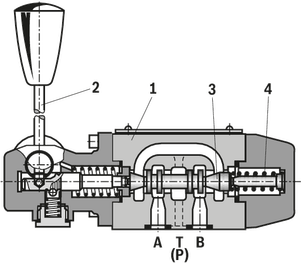
Type WM.. valves are mechanical, manually actuated directional spool valves. They control the start, stop and direction of a flow. Directional valves basically consist of housing (1), one type of actuation (2) (hand lever), control spool (3) and one or two return springs (4). In de-energized state, the return springs (4) maintain the control spool (3) in central or starting position - if the rotary knob is actuated with a detent. The control spool (3) is moved to the desired spool position by means of the type of actuation (2).
Detent
Directional valves with rotary knob are generally designed with detent. Directional valves with hand lever are optionally available as 2 or 3 position valves with detent. Directional valves with roller plunger are generally designed without detent. If types of actuation with detent are used, each spool position can be locked, depending on the valve type.
Throttle insert
The use of a throttle insert is required when due to prevailing operating conditions, flows can occur during the switching processes, which exceed the performance limit of the valve. It is inserted in channel P of the directional valve.
Type 4WMM 6 D5X/F
Type 4WM. 6 ..5X/..B..
01 | Mineral oil | M | |||
02 | 3 main ports | 3 | |||
4 main ports | 4 | ||||
03 | Seat valve | SEW | |||
04 | Size 10 | 10 | |||
05 | Main ports | 3 | 4 | ||
Symbol |  | ● | – | U | |
 | ● | – | C | ||
 | – | ● | D | ||
 | – | ● | Y | ||
● = available | |||||
06 | Component series 10 ... 19 (10 ... 19: unchanged installation and connection dimensions) | 1X | |||
07 | Operating pressure 420 bar | 420 bar | |||
Operating pressure 630 bar | 630 bar | ||||
08 | Solenoid (air-gap) with detachable coil | M | |||
09 | Direct voltage 24 V | G24 | |||
Nominal voltage 96 V at DC solenoid in operation with alternating voltage (AC voltage mains 110/120 V - 50/60 Hz with an admissible voltage tolerance of +/- 10 %) | G96 | ||||
Nominal voltage 110 V at DC solenoid with operation with AC voltage mains (AC voltage mains 110 V/120 V – 50/60 Hz with an admissible voltage tolerance of +/-10 %) | G110 | ||||
Nominal voltage 205 V at DC solenoid with operation with AC voltage mains (AC voltage mains 230 V – 50/60 Hz with an admissible voltage tolerance of +/- 10 %) | G205 2) | ||||
10 | With concealed manual override | N9 | |||
Without manual override | no code | ||||
Electrical connection | |||||
11 | Individual connection | ||||
Without mating connector, with connector DIN EN 175301-803 | K41;2) | ||||
With M12x1 plug-in connection, high-performance version 5-pole, integrated interference protection circuit, operating display with LED | K72L3) | ||||
Spool position monitoring | |||||
12 | Without position switch | no code | |||
Monitored spool position "a" | QMAG24 | ||||
Monitored spool position "b" | QMBG24 | ||||
13 | Without check valve insert, without throttle insert | no code | |||
With check valve insert | P | ||||
Throttle Ø 1.2 mm | B12 | ||||
Throttle Ø 1.5 mm | B15 | ||||
Throttle Ø 1.8 mm | B18 | ||||
Throttle Ø 2.0 mm | B20 | ||||
Throttle Ø 2.2 mm | B22 | ||||
Seal material | |||||
14 | NBR seals | no code | |||
FKM seals (other seals upon request) | V | ||||
Observe compatibility of seals with hydraulic fluid used. | |||||
15 | Further details in the plain text | * | |||
01 | 02 | 03 | 04 | 05 | 06 | 07 | 08 | 09 | 10 | 11 | 12 | 13 | 14 | |||
M | – | SEW | 10 | 1X | / | M | K4 | / |
Preferred types and standard units are contained in the EPS (standard price list).
01 | Mineral oil | M | |||
02 | 3 main ports | 3 | |||
4 main ports | 4 | ||||
03 | Seat valve | SEW | |||
04 | Size 10 | 10 | |||
05 | Main ports | 3 | 4 | ||
Symbol | | ● | – | U | |
| | ● | – | C | ||
| | – | ● | D | ||
| | – | ● | Y | ||
● = available | |||||
06 | Component series 10 ... 19 (10 ... 19: unchanged installation and connection dimensions) | 1X | |||
07 | Operating pressure 420 bar | 420 bar | |||
Operating pressure 630 bar | 630 bar | ||||
08 | Solenoid (air-gap) with detachable coil | M | |||
09 | Direct voltage 24 V | G24 | |||
Nominal voltage 96 V at DC solenoid in operation with alternating voltage (AC voltage mains 110/120 V - 50/60 Hz with an admissible voltage tolerance of +/- 10 %) | G96 | ||||
Nominal voltage 110 V at DC solenoid with operation with AC voltage mains (AC voltage mains 110 V/120 V – 50/60 Hz with an admissible voltage tolerance of +/-10 %) | G110 | ||||
Nominal voltage 205 V at DC solenoid with operation with AC voltage mains (AC voltage mains 230 V – 50/60 Hz with an admissible voltage tolerance of +/- 10 %) | G205 2) | ||||
10 | With concealed manual override | N9 | |||
Without manual override | no code | ||||
Electrical connection | |||||
11 | Individual connection | ||||
Without mating connector, with connector DIN EN 175301-803 | K41;2) | ||||
With M12x1 plug-in connection, high-performance version 5-pole, integrated interference protection circuit, operating display with LED | K72L3) | ||||
Spool position monitoring | |||||
12 | Without position switch | no code | |||
Monitored spool position "a" | QMAG24 | ||||
Monitored spool position "b" | QMBG24 | ||||
13 | Without check valve insert, without throttle insert | no code | |||
With check valve insert | P | ||||
Throttle Ø 1.2 mm | B12 | ||||
Throttle Ø 1.5 mm | B15 | ||||
Throttle Ø 1.8 mm | B18 | ||||
Throttle Ø 2.0 mm | B20 | ||||
Throttle Ø 2.2 mm | B22 | ||||
Seal material | |||||
14 | NBR seals | no code | |||
FKM seals (other seals upon request) | V | ||||
Observe compatibility of seals with hydraulic fluid used. | |||||
15 | Further details in the plain text | * | |||
01 | 02 | 03 | 04 | 05 | 06 | 07 | 08 | 09 | 10 | 11 | 12 | 13 | 14 | |||
M | – | SEW | 10 | 1X | / | M | K4 | / |
Preferred types and standard units are contained in the EPS (standard price list).
Size | 6 | ||
Weight (approx.) | kg | 1.4 | |
Installation position | any | ||
Ambient temperature range | NBR seals | °C | -20 … +80 |
FKM seals | °C | -20 … +80 | |
Operating force | without tank pressure, with/without detent | N | 20 |
at a tank pressure of 150 bar 1) | N | 30 | |
| 1) | at 150 bar |
Size | 6 | ||
Maximum operating pressure | Port P | bar | 315 |
Port A | bar | 315 | |
Port B | bar | 315 | |
Port T 1) | bar | 160 | |
Maximum flow | l/min | 60 | |
Flow cross-section (spool position 0) | Symbol Q | approx. 6 % of nominal cross-section | |
Symbol W | approx. 3 % of nominal cross-section | ||
Hydraulic fluid | see table | ||
Hydraulic fluid temperature range | NBR seals | °C | -30 … +80 |
FKM seals | °C | -20 … +80 | |
Viscosity range | mm²/s | 2.8 … 500 | |
Maximum admissible degree of contamination of the hydraulic fluid 2) | Class 20/18/15 according to ISO 4406 (c) | ||
| 1) | With symbols A or B, port T must be used as leakage oil connection if the operating pressure exceeds the admissible tank pressure. |
| 2) | The cleanliness classes specified for the components must be adhered to in hydraulic systems. Effective filtration prevents faults and simultaneously increases the life cycle of the components. For the selection of the filters, see www.boschrexroth.com/filter. |
Hydraulic fluid | Classification | Suitable sealing materials | Standards | |
Mineral oils | HL, HLP, HLPD, HVLP, HVLPD | NBR, FKM | DIN 51524 | |
Bio-degradable | Insoluble in water | HETG | NBR, FKM | VDMA 24568 |
HEES | FKM | |||
Soluble in water | HEPG | FKM | VDMA 24568 | |
Containing water | Water-free | HFDU, HFDR | FKM | ISO 12922 |
Containing water | HFC (Fuchs Hydrotherm 46M, Petrofer Ultra Safe 620) | NBR, HNBR | ISO 12922 | |
Important information on hydraulic fluids!
Flame-resistant – containing water:
| ||||
The electric connection is realized via a 4-pole mating connector (separate order) with connection thread M12 x 1.
Connection voltage (DC voltage) | V | 24 | ||
Voltage tolerance (connection voltage) | +30 %/-15 % | |||
Admissible residual ripple | % | ≤ 10 | ||
Max. load capacity | mA | 400 | ||
Switching outputs 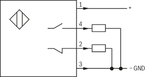 | PNP transistor outputs, load between switching outputs and GND | |||
Pinout  | 1 | V | 24 | |
2, 4 | Switching output | mA | 400 | |
3 | Earthing (GND) | V | 0 | |
Size | 6 | ||
Weight (approx.) | kg | 1.4 | |
Installation position | any | ||
Ambient temperature range | NBR seals | °C | -20 … +80 |
FKM seals | °C | -20 … +80 | |
Operating force | without tank pressure, with/without detent | N | 20 |
at a tank pressure of 150 bar 1) | N | 30 | |
| 1) | at 150 bar |
Size | 6 | ||
Maximum operating pressure | Port P | bar | 315 |
Port A | bar | 315 | |
Port B | bar | 315 | |
Port T 1) | bar | 160 | |
Maximum flow | l/min | 60 | |
Flow cross-section (spool position 0) | Symbol Q | approx. 6 % of nominal cross-section | |
Symbol W | approx. 3 % of nominal cross-section | ||
Hydraulic fluid | see table | ||
Hydraulic fluid temperature range | NBR seals | °C | -30 … +80 |
FKM seals | °C | -20 … +80 | |
Viscosity range | mm²/s | 2.8 … 500 | |
Maximum admissible degree of contamination of the hydraulic fluid 2) | Class 20/18/15 according to ISO 4406 (c) | ||
| 1) | With symbols A or B, port T must be used as leakage oil connection if the operating pressure exceeds the admissible tank pressure. |
| 2) | The cleanliness classes specified for the components must be adhered to in hydraulic systems. Effective filtration prevents faults and simultaneously increases the life cycle of the components. For the selection of the filters, see www.boschrexroth.com/filter. |
Hydraulic fluid | Classification | Suitable sealing materials | Standards | |
Mineral oils | HL, HLP, HLPD, HVLP, HVLPD | NBR, FKM | DIN 51524 | |
Bio-degradable | Insoluble in water | HETG | NBR, FKM | VDMA 24568 |
HEES | FKM | |||
Soluble in water | HEPG | FKM | VDMA 24568 | |
Containing water | Water-free | HFDU, HFDR | FKM | ISO 12922 |
Containing water | HFC (Fuchs Hydrotherm 46M, Petrofer Ultra Safe 620) | NBR, HNBR | ISO 12922 | |
Important information on hydraulic fluids!
Flame-resistant – containing water:
| ||||
The electric connection is realized via a 4-pole mating connector (separate order) with connection thread M12 x 1.
Connection voltage (DC voltage) | V | 24 | ||
Voltage tolerance (connection voltage) | +30 %/-15 % | |||
Admissible residual ripple | % | ≤ 10 | ||
Max. load capacity | mA | 400 | ||
Switching outputs | PNP transistor outputs, load between switching outputs and GND | |||
Pinout | 1 | V | 24 | |
2, 4 | Switching output | mA | 400 | |
3 | Earthing (GND) | V | 0 | |
Dimensions in mm
Dimensions in mm

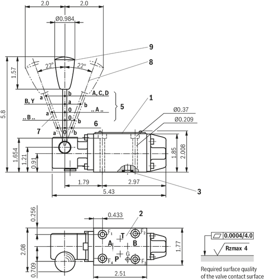
1 | Name plate |
2 | Porting pattern according toISO 4401-03-02-0-05 (with locating hole for locking pin ISO 8752-3x8-St, material no. R900005694, separate order) |
3 | Identical seal rings for ports A, B, P, T |
5 | Valve with 2 spool positions |
6 | Valve with 3 spool positions |
7 | Spool position “a” |
8 | Spool position “b” |
9 | Spool position “0”, “a” and “b” (a and b for valves with 2 spool positions) |
Subplates according to data sheet 45052 (separate order)
(without locating hole)
G 341/01 (G1/4)
G 342/01 (G3/8)
G 502/01 (G1/2)
(with locating hole)
G 341/60 (G1/4)
G 342/60 (G3/8)
G 502/60 (G1/2)
G 341/12 (SAE-6)1)
G 342/12 (SAE-8)1)
G 502/12 (SAE-10)1)
1) On request
Valve mounting screws (separate order)
Clamping length 42 mm:
4 hexagon socket head cap screws, metric
ISO 4762 - M5 x 50 - 10.9-flZn-240h-L
(friction coefficient μtotal = 0.09 to 0.14);
tightening torque MA = 7 Nm ± 10 %,
Material no. R913000064
or
4 hexagon socket head cap screws
ISO 4762 - M5 x 50 - 10.9 (self procurement)
(friction coefficient μtotal = 0.12 to 0.17);
tightening torque MA = 8.1 Nm ± 10 %
4 hexagon socket head cap screws UNC
10-24 UNC x 2″ ASTM-A574
(friction coefficient μtotal = 0.19 to 0.24);
tightening torque MA = 11 Nm ± 15 %,
(friction coefficient μtotal = 0.12 to 0.17);
tightening torque MA = 8 Nm ± 10 %,
material no. R978800693
Dimensions in mm

| 1) | For dimensions, see valve dimensions |
Dimensions in mm

The dimensions are nominal dimensions which are subject to tolerances.
Dimensions in mm
Dimensions in mm
1 | Name plate |
2 | Porting pattern according toISO 4401-03-02-0-05 (with locating hole for locking pin ISO 8752-3x8-St, material no. R900005694, separate order) |
3 | Identical seal rings for ports A, B, P, T |
5 | Valve with 2 spool positions |
6 | Valve with 3 spool positions |
7 | Spool position “a” |
8 | Spool position “b” |
9 | Spool position “0”, “a” and “b” (a and b for valves with 2 spool positions) |
Subplates according to data sheet 45052 (separate order)
(without locating hole)
G 341/01 (G1/4)
G 342/01 (G3/8)
G 502/01 (G1/2)
(with locating hole)
G 341/60 (G1/4)
G 342/60 (G3/8)
G 502/60 (G1/2)
G 341/12 (SAE-6)1)
G 342/12 (SAE-8)1)
G 502/12 (SAE-10)1)
1) On request
Valve mounting screws (separate order)
Clamping length 42 mm:
4 hexagon socket head cap screws, metric
ISO 4762 - M5 x 50 - 10.9-flZn-240h-L
(friction coefficient μtotal = 0.09 to 0.14);
tightening torque MA = 7 Nm ± 10 %,
Material no. R913000064
or
4 hexagon socket head cap screws
ISO 4762 - M5 x 50 - 10.9 (self procurement)
(friction coefficient μtotal = 0.12 to 0.17);
tightening torque MA = 8.1 Nm ± 10 %
4 hexagon socket head cap screws UNC
10-24 UNC x 2″ ASTM-A574
(friction coefficient μtotal = 0.19 to 0.24);
tightening torque MA = 11 Nm ± 15 %,
(friction coefficient μtotal = 0.12 to 0.17);
tightening torque MA = 8 Nm ± 10 %,
material no. R978800693
Dimensions in mm
| 1) | For dimensions, see valve dimensions |
Dimensions in mm
The dimensions are nominal dimensions which are subject to tolerances.


