| Availability: | |
|---|---|
| Quantity: | |

4WEH 16 J7X/6HG24N9ETK4/B10
Rexroth
R901108754
4/3-, 4/2- or 3/2-way version
Types of actuation (internal or external pilot control):
– Electro-hydraulic (type WEH)
– Hydraulic (type WH)
For subplate mounting
Porting pattern according to ISO 4401
Spring or pressure centering, spring end position or hydraulic end position
Wet-pin DC or AC solenoids, optional
Electric connection as single or central connection
Optional versions:
- Manual override
- Switching time adjustment
- Preload valve in channel P of the main valve
- Stroke setting and/or spool position monitoring
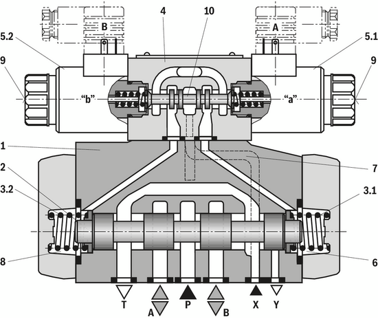
The valve type WEH is a directional spool valve with electro-hydraulic actuation. It controls the start, stop and direction of a flow. The directional valve basically consists of the main valve with housing (1), the main control spool (2), one or two return springs (3.1) and (3.2), as well as the pilot control valve (4) with one or two solenoids "a" (5.1) and/or "b" (5.2).
For unobjectionable functioning, the hydraulic system has to be bled properly.
For valves with 3 spool positions, the main control spool (2) in the main valve is held in zero position or initial position by means of two springs, for valves with 2 spool positions by pressurization and spring. In the initial position, the two spring chambers (6) and (8) are connected with the tank in a depressurized form via the pilot control valve (4). Via the control line (7), the pilot control valve is supplied with pilot oil. Supply can be implemented internally or externally (externally via port X). Upon actuation of the pilot control valve, e.g. solenoid "a", the pilot control spool (10) is moved to the left and thus, the spring chamber (8) is pressurized with pilot pressure. The spring chamber (6) remains depressurized. The pilot pressure acts on the left side of the main control spool (2) and moves it against the spring (3.1). This connects port P with B and A with T in the main valve.
On switching off of solenoid, the pilot control spool (10) returns to its initial position (except impulse spool). The spring chamber (8) is unloaded to the tank. The pilot oil return is implemented internally (via channel T) or externally (via channel Y). An optional manual override (9) allows for moving of the pilot control spool (10) without solenoid energization.
Notice:
The return springs (3.1) and (3.2) in the spring chambers (6) and (8) hold the main control spool (2) in central position without pilot pressure even with, for example, vertical valve positioning.
Due to the design principle, internal leakage is inherent to the valves, which may increase over the life cycle.
Valve type WH is a directional spool valve with hydraulic actuation. It controls the start, stop and direction of a flow. The directional valve basically consists of the valve housing (1), the main control spool (2), one or two return springs (3.1) and (3.2) at valves with spring return or spring centering as well as the diversion plate (11).
The main control spool (2) is actuated directly by pressurization. The main control spool (2) is held in zero or initial position by springs or pressurization. Pilot oil supply and return are external (see Pilot oil supply).
4/3 directional valve with spring centering of the control spool
With this version, the main control spool (2) is held in zero position by two return springs (3.1) and (3.2). Via the diversion plate (11), the spring chamber (6) is connected to port Y, the spring chamber (8) to port X.
With pilot pressure loading of one of the two front sides of the main control spool (2), the spool is moved to the spool position. In the valve, the required ports are connected in this way. The spring on the opposite side returns the spool to the zero or initial position at pressure relief of the pressurized control spool area.

4/3 directional valve with pressure centering of the main control spool
The main control spool (2) in the main valve is kept in the zero position by pressurization of the two front faces. One centering bush (12) rests on the housing and fixes the control spool position. By pressure relief of one front face, the main control spool (2) is moved to the spool position.
The unloaded control spool face displaces the returning pilot oil into channel Y (external) via the pilot control valve.
Notice:
The springs (3.1) and (3.2) do not have a return function in this version. They hold the main control spool (2) in central position in the depressurized condition and with horizontal installation.
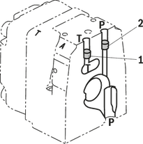
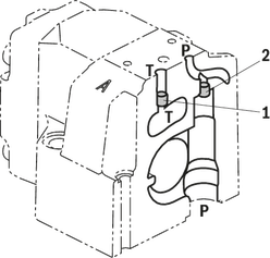

1 |
Plug screw M6 according to DIN 906, wrench size 3 - Pilot oil return |
2 |
Plug screw M6 according to DIN 906, wrench size 3 – pilot oil supply |
3 |
Plug screw M12 x 1.5 according DIN 906, wrench size 6 |
Pilot oil supply |
Pilot oil return |
||
External |
2, 3 closed |
External |
1 closed |
Internal |
2, 3 open |
Internal |
1 open |
Type WH…
The pilot oil supply and return is implemented externally via channel X and Y.
Type WEH...
The pilot oil supply is implemented externally - via channel X - from a separate pressure supply.
The pilot oil return is implemented externally via the Y channel into the tank.
Type WEH…E…
The pilot oil supply is implemented internally from channel P of the main valve. (see Technical data)
The pilot oil return is implemented externally via the Y channel into the tank. In the subplate, port X is closed.
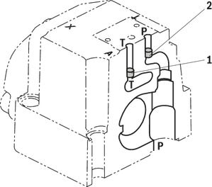
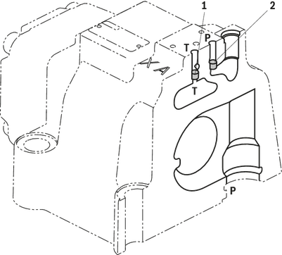
Type WEH…ET…
The pilot oil supply is implemented internally from channel P of the main valve.
The pilot oil return is implemented internally via the channel T into the tank. In the subplate, ports X and Y are closed.
Type WEH…T…
The pilot oil supply is implemented externally - via channel X - from a separate pressure supply.
The pilot oil return is implemented internally via the channel T into the tank. In the subplate, port Y is closed.
Throttle insert
Use of the throttle insert (5) is necessary if the pilot oil supply in channel P of the pilot control valve is to be limited. The throttle insert (5) is inserted in channel P of the pilot control valve.

4 |
Pilot control valve |
5 |
Main valve |
6 |
Throttle insert |
Notices:
The modification of the pilot oil supply may only be performed by authorized specialists or at the factory.
Pilot oil supply X or return Y external:
The maximum admissible operating parameters of the pilot control valve must be observed (see data sheet 23178).
Maximum pilot pressure: please observe the Technical data.
Pilot oil supply internal (version "ET" and "E"):
Minimum pilot pressure: please observe the Technical data.
In order to prevent inadmissibly high pressure peaks, a "B10" throttleinsert has to be provided in port P of the pilot control valve.
In connection with version "H", the pressure reducing valve "D3" (see switching time adjustment) is also required.
The valve type WEH is a directional spool valve with electro-hydraulic actuation. It controls the start, stop and direction of a flow. The directional valve basically consists of the main valve with housing (1), the main control spool (2), one or two return springs (3.1) and (3.2), as well as the pilot control valve (4) with one or two solenoids "a" (5.1) and/or "b" (5.2).
For unobjectionable functioning, the hydraulic system has to be bled properly.
For valves with 3 spool positions, the main control spool (2) in the main valve is held in zero position or initial position by means of two springs, for valves with 2 spool positions by pressurization and spring. In the initial position, the two spring chambers (6) and (8) are connected with the tank in a depressurized form via the pilot control valve (4). Via the control line (7), the pilot control valve is supplied with pilot oil. Supply can be implemented internally or externally (externally via port X). Upon actuation of the pilot control valve, e.g. solenoid "a", the pilot control spool (10) is moved to the left and thus, the spring chamber (8) is pressurized with pilot pressure. The spring chamber (6) remains depressurized. The pilot pressure acts on the left side of the main control spool (2) and moves it against the spring (3.1). This connects port P with B and A with T in the main valve.
On switching off of solenoid, the pilot control spool (10) returns to its initial position (except impulse spool). The spring chamber (8) is unloaded to the tank. The pilot oil return is implemented internally (via channel T) or externally (via channel Y). An optional manual override (9) allows for moving of the pilot control spool (10) without solenoid energization.
Notice:
The return springs (3.1) and (3.2) in the spring chambers (6) and (8) hold the main control spool (2) in central position without pilot pressure even with, for example, vertical valve positioning.
Due to the design principle, internal leakage is inherent to the valves, which may increase over the life cycle.
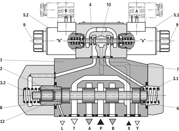
Valve type WH is a directional spool valve with hydraulic actuation. It controls the start, stop and direction of a flow. The directional valve basically consists of the valve housing (1), the main control spool (2), one or two return springs (3.1) and (3.2) at valves with spring return or spring centering as well as the diversion plate (11).
The main control spool (2) is actuated directly by pressurization. The main control spool (2) is held in zero or initial position by springs or pressurization. Pilot oil supply and return are external (see Pilot oil supply).
4/3 directional valve with spring centering of the control spool
With this version, the main control spool (2) is held in zero position by two return springs (3.1) and (3.2). Via the diversion plate (11), the spring chamber (6) is connected to port Y, the spring chamber (8) to port X.
With pilot pressure loading of one of the two front sides of the main control spool (2), the spool is moved to the spool position. In the valve, the required ports are connected in this way. The spring on the opposite side returns the spool to the zero or initial position at pressure relief of the pressurized control spool area.
4/3 directional valve with pressure centering of the main control spool
The main control spool (2) in the main valve is kept in the zero position by pressurization of the two front faces. One centering bush (12) rests on the housing and fixes the control spool position. By pressure relief of one front face, the main control spool (2) is moved to the spool position.
The unloaded control spool face displaces the returning pilot oil into channel Y (external) via the pilot control valve.
Notice:
The springs (3.1) and (3.2) do not have a return function in this version. They hold the main control spool (2) in central position in the depressurized condition and with horizontal installation.
1 |
Plug screw M6 according to DIN 906, wrench size 3 - Pilot oil return |
2 |
Plug screw M6 according to DIN 906, wrench size 3 – pilot oil supply |
3 |
Plug screw M12 x 1.5 according DIN 906, wrench size 6 |
Pilot oil supply |
Pilot oil return |
||
External |
2, 3 closed |
External |
1 closed |
Internal |
2, 3 open |
Internal |
1 open |
Type WH…
The pilot oil supply and return is implemented externally via channel X and Y.
Type WEH...
The pilot oil supply is implemented externally - via channel X - from a separate pressure supply.
The pilot oil return is implemented externally via the Y channel into the tank.
Type WEH…E…
The pilot oil supply is implemented internally from channel P of the main valve. (see Technical data)
The pilot oil return is implemented externally via the Y channel into the tank. In the subplate, port X is closed.
Type WEH…ET…
The pilot oil supply is implemented internally from channel P of the main valve.
The pilot oil return is implemented internally via the channel T into the tank. In the subplate, ports X and Y are closed.
Type WEH…T…
The pilot oil supply is implemented externally - via channel X - from a separate pressure supply.
The pilot oil return is implemented internally via the channel T into the tank. In the subplate, port Y is closed.
Throttle insert
Use of the throttle insert (5) is necessary if the pilot oil supply in channel P of the pilot control valve is to be limited. The throttle insert (5) is inserted in channel P of the pilot control valve.
4 |
Pilot control valve |
5 |
Main valve |
6 |
Throttle insert |
Notices:
The modification of the pilot oil supply may only be performed by authorized specialists or at the factory.
Pilot oil supply X or return Y external:
The maximum admissible operating parameters of the pilot control valve must be observed (see data sheet 23178).
Maximum pilot pressure: please observe the Technical data.
Pilot oil supply internal (version "ET" and "E"):
Minimum pilot pressure: please observe the Technical data.
In order to prevent inadmissibly high pressure peaks, a "B10" throttleinsert has to be provided in port P of the pilot control valve.
In connection with version "H", the pressure reducing valve "D3" (see switching time adjustment) is also required.
01 | 02 | 03 | 04 | 05 | 06 | 07 | 08 | 09 | 10 | 11 | 12 | 13 | 14 | 15 | 16 | 17 | 18 | 19 | 20 | 21 | 22 | ||
/ | / | * |
01 | Up to 4100 psi | no code |
Up to 5100 psi | H- | |
Main ports | ||
02 | 3-way version | 3 |
4-way version | 4 | |
Type of actuation | ||
03 | Hydraulic | WH |
Electro-hydraulic | WEH | |
Size | ||
04 | NG10 | 10 |
NG16 | 16 | |
NG25 (version "W.H 22") | 22 | |
NG25 (version "W.H 25") | 25 | |
Size 32 | 32 | |
Spool return in the main valve | ||
05 | By means of springs | no code |
Hydraulic 1) | H | |
06 | Symbols; for the possible version, see "Symbols/Circuit diagrams" | |
Component series | ||
07 | Component series 40 … 49 (40 … 49: unchanged installation and connection dimension) – NG10 | 4X |
Component series 60 … 69 (60 … 69: unchanged installation and connection dimension) – NG25 ("W.H 25") and NG32 | 6X | |
Component series 70 … 79 (70 … 79: unchanged installation and connection dimension) – NG16 (from series 72) andNG25 ("W.H 22") | 7X | |
Control spool return in the pilot control valve with 2 spool positions and 2 solenoids (only possible with symbols A, B, C, D, K, Z and hydraulic control spool return in the main valve) | ||
08 | With spring return | no code |
Without spring return | O | |
Without spring return with detent 2) | OF | |
Pilot control valve 2) | ||
09 | High-power valve (data sheet 23178) | 6E |
Electrical voltages 2) | ||
10 | Direct voltage 24 V | G24 |
Alternating voltage 230 V, 50/60 Hz | W230 | |
Manual override | ||
11 | Without manual override | no code |
With manual override | N | |
With concealed manual override | N9 | |
Corrosion resistance (outside) | ||
12 | None (valve housing primed) | no code |
Improved corrosion protection (240 h salt spray test according to EN ISO 9227) | J3 | |
Pilot oil flow 3) | ||
13 | External pilot oil supply, external pilot oil return 4) | no code |
Internal pilot oil supply, external pilot oil return 4; 5) | E | |
Pilot oil supply internal, pilot oil return internal 5) | ET | |
External pilot oil supply, internal pilot oil return 4) | T | |
Switching time adjustment | ||
14 | Without switching time adjustment | no code |
Switching time adjustment as supply control | S | |
Switching time adjustment as discharge control | S2 | |
Electrical connection 2) | ||
15 | Individual connection | |
Without mating connector, connector according to DIN EN 175301-803 | K4 6) | |
Spool position monitoring | ||
16 | Without position switch | no code |
Monitored spool position "a" | QMAG24 | |
Monitored spool position "b" | QMBG24 | |
Monitored spool position "a" and "b" | QMABG24 | |
Monitored rest position | QM0G24 | |
Stroke setting | ||
17 | Stroke setting on valve side A and B | 10 |
Stroke setting on valve side A | 11 | |
Stroke setting on valve side B | 12 | |
Throttle insert 2) | ||
18 | Without throttle insert | no code |
Throttle Ø 0.031 inch | B08 | |
Throttle Ø 0.039 inch | B10 | |
Throttle Ø 0.047 inch | B12 | |
Throttle Ø 0.059 inch | B15 | |
Throttle Ø 0.079 inch | B20 | |
Throttle Ø 0.098 inch | B25 | |
preload valve (not for NG10) 2) | ||
19 | Without pre-decompression | no code |
With preload valve | P4,5 | |
20 | Without pressure reducing valve | no code |
With pressure reducing valve | D3 7) | |
Seal material (observe compatibility of seals with hydraulic fluid used, see "Technical data") | ||
21 | NBR seals | no code |
FKM seals | V | |
22 | Further details in the plain text | * |
| 1) | – 2 spool positions (hydraulic end position): only symbols C, D, K, Z, Y – 3 switching positions (hydraulically centered): only NG16, NG25 ("4W.H 25") and NG32 |
| 2) | Only with electro-hydraulic actuation (type WEH) |
| 3) | For type WH... only "no code"; version "ET" and "T" with 3-spool position valve, pressure-centered only possible if ppilot ≥ 2 x ptank + ppilot min |
| 4) | Pilot oil supply X or return Y external: – Minimum pilot pressure: please observe "Technical data". – Maximum pilot pressure: please observe "Technical data". – The maximum admissible operating parameters of the pilot control valve must be observed (see data sheet 23178). |
| 5) | Pilot oil supply internal (version "ET" and "E"): – Minimum pilot pressure: please observe "Technical data". – Maximum pilot pressure: please observe "Technical data". – With a higher pilot pressure, use of a pressure reducing valve "D3" is required (if it is not used pilot pressure = operating pressure at the port). – In order to prevent inadmissibly high pressure peaks, a "B10" throttle insert has to be provided in port P of the pilot control valve (see "Product description"). – In connection with version "H", the pressure reducing valve "D3" is also required. |
| 6) | Mating connectors, separate order, see "Accessories" |
| 7) | Only in connection with the "B10" throttle insert |
Type | WH | H-WH | WEH | H-WEH | WH | H-WH | WEH | H-WEH | WH22 | H-WH22 | WEH22 | H-WEH22 | WH25 | H-WH25 | WEH25 | H-WEH25 | WH | H-WH | WEH | H-WEH | ||
Size | 10 | 16 | 25 | 32 | ||||||||||||||||||
Weight (approx.) | Valve with one solenoid | lbs | 14 | 19 | 25 | 39 | 39 | |||||||||||||||
Valve with two solenoids, spring-centered | lbs | 15 | 20 | 26 | 42 | 90 | ||||||||||||||||
Valve with two solenoids, pressure-centered | lbs | 15 | 20 | 26 | 42 | 90 | ||||||||||||||||
Valve witch hydraulic actuation (type WH...) | lbs | 12 | 16 | 23 | 36 | 87 | ||||||||||||||||
Switching time adjustment "S" and "S2" | lbs | 1.8 | ||||||||||||||||||||
Pressure reducing valve "D3" | lbs | 0.88 | ||||||||||||||||||||
Installation position | With suspended installation, higher sensitivity to contamination, horizontal is recommended. For valves with hydraulic control spool return "H" and symbol C, D, K, Z, Y, horizontal is required. | |||||||||||||||||||||
Ambient temperature range | NBR seals | °F | -4 … +122 | |||||||||||||||||||
FKM seals | °F | +5 … +122 | ||||||||||||||||||||
Version for HFC hydraulic fluid | °F | -4 … +122 | ||||||||||||||||||||
Storage temperature range | °F | +41 … +104 | ||||||||||||||||||||
Surface protection | Valve body | Coating, layer thickness max. 3937 µin | ||||||||||||||||||||
MTTFD values according to EN ISO 13849 | Years | 150 | 100 | 150 | 100 | 150 | 100 | 150 | 100 | 150 | 100 | |||||||||||
Type | WH | H-WH | WEH | H-WEH | WH | H-WH | WEH | H-WEH | WH22 | H-WH22 | WEH22 | H-WEH22 | WH25 | H-WH25 | WEH25 | H-WEH25 | WH | H-WH | WEH | H-WEH | |||
Size | 10 | 16 | 25 | 32 | |||||||||||||||||||
Maximum operating pressure | Port P | psi | 4100 | 5100 | 4100 | 5100 | 4100 | 5100 | 4100 | 5100 | 4100 | 5100 | 4100 | 5100 | 4100 | 5100 | 4100 | 5100 | 4100 | 5100 | 4100 | 5100 | |
Anschluss A | psi | 4100 | 5100 | 4100 | 5100 | 4100 | 5100 | 4100 | 5100 | 4100 | 5100 | 4100 | 5100 | 4100 | 5100 | 4100 | 5100 | 4100 | 5100 | 4100 | 5100 | ||
Port B | psi | 4100 | 5100 | 4100 | 5100 | 4100 | 5100 | 4100 | 5100 | 4100 | 5100 | 4100 | 5100 | 4100 | 5100 | 4100 | 5100 | 4100 | 5100 | 4100 | 5100 | ||
Port T | External pilot oil return Y | psi | 4100 | 4550 | 4100 | 4550 | 3600 | ||||||||||||||||
Internal pilot oil return Y (direct voltage) | psi | 3050 1) | 3050 1) | 3050 1) | 3050 1) | 3050 1) | |||||||||||||||||
Internal pilot oil return Y (alternating voltage) | psi | 2300 1) | 2300 1) | 2300 1) | 2300 1) | 2300 1) | |||||||||||||||||
Port Y | Pilot oil return, external | psi | 3600 | 3600 | 3050 | 3600 | 3600 | ||||||||||||||||
Pilot oil return, external (direct voltage) | psi | 3050 | 3050 | 3050 | 3050 | 3050 | |||||||||||||||||
Pilot oil return, external (alternating voltage) | psi | 2300 | 2300 | 2300 | 2300 | 2300 | |||||||||||||||||
Hydraulic fluid | see table "Hydraulic fluid" | ||||||||||||||||||||||
Hydraulic fluid temperature range | NBR seals | °F | -4 … +176 2) | ||||||||||||||||||||
FKM seals | °F | +5 … +176 2) | |||||||||||||||||||||
HFC hydraulic fluid | °F | -4 … +122 2) | |||||||||||||||||||||
Viscosity range | cSt | 2.8 … 500 | |||||||||||||||||||||
Maximum admissible degree of contamination of the hydraulic fluid, cleanliness class according to ISO 4406 (c) | Class 20/18/15 3) | ||||||||||||||||||||||
Maximum pilot pressure | psi | 3600 4) | 3050 4) | 3600 4) | |||||||||||||||||||
Minimum pilot pressure | External pilot oil supply X (all symbols), internal pilot oil supply (only symbols D, K, E, J, L, M, Q, R, U, W) | 3-spool position valve, spring-centered | psi | 175 | 200 | 150 | 180 | 150 | 180 | 190 | 123 | ||||||||||||
3-spool position valve, pressure-centered | psi | 230 | 260 | 123 | |||||||||||||||||||
2-spool position valve, spring end position | psi | 145 | 200 | 160 | 200 | 160 | 200 | 190 | 145 | ||||||||||||||
2-spool position valve, hydraulic end position | psi | 100 | 200 | 115 | 115 | 75 | |||||||||||||||||
Internal pilot oil supply X (with symbols C, F, G, H, P, T, V, Z, S) | psi | 108 5) | 65 6) | 65 6) | 65 6) | 65 6) | |||||||||||||||||
Free flow cross-sections in zero position with symbols Q, V and W | Symbol Q | A – T; B – T | in² | 0.02 | 0.05 | 0.12 | 0.13 | 0.12 | |||||||||||||||
Symbol V | P – A; P – B | in² | 0.02 | 0.05 | 0.11 | 0.13 | 0.11 | ||||||||||||||||
A – T; B – T | in² | 0.02 | 0.05 | 0.13 | |||||||||||||||||||
Symbol W | A – T; B – T | in² | 0.004 | 0.009 | 0.016 | 0.022 | 0.031 | ||||||||||||||||
Pilot volume for switching process | 3-spool position valve, spring-centered | in³ | 0.12 | 0.35 | 0.47 | 0.87 | 1.79 | ||||||||||||||||
2-spool position valve | in³ | 0.25 | 0.7 | 0.93 | 1.73 | 3.59 | |||||||||||||||||
3-spool position valve, pressure-centered | from zero position in switching position “a” | in³ | 0.17 | 0.44 | 0.88 | ||||||||||||||||||
from switching position “a” in zero position | in³ | 0.35 | 0.18 | 0.87 | 0.43 | 1.79 | 0.92 | ||||||||||||||||
from zero position in switching position “b” | in³ | 0.35 | 0.87 | 0.86 | 1.79 | ||||||||||||||||||
from switching position “b” in zero position | in³ | 0.52 | 0.17 | 1.21 | 0.35 | 2.67 | 0.88 | ||||||||||||||||
Pilot flow for shortest switching time, approx. | gpm | 9.2 | 11.9 | ||||||||||||||||||||
| 1) | As a 3-spool position valve, pressure-centered only possible if ppilot ≥ 2 x ptank + ppilot min |
| 2) | If type WH is used in potentially explosion-proof areas, see data sheet 07011. |
| 3) | The cleanliness classes specified for the components must be adhered to in hydraulic systems. Effective filtration prevents faults and simultaneously increases the life cycle of the components. For the selection of the filters, see www.boschrexroth.com/filter. |
| 4) | Pilot oil supply internal: |
| 5) | For symbols C, F, G, H, P, T, V, Z, an internal pilot oil supply is only possible if the flow from P to T in the central position (for 3-spool position valve) or while crossing the central position (for 2-spool position valve) is so large that the pressure differential of P to T reaches a value of at least 109 psi. For a pressure differential below 109 psi, a check valve with a cracking pressure of 109 psi is to be provided in the return line to the tank. An external pilot oil supply Y is required. |
| 6) | Pilot oil supply X internal is only possible for a pressure at P of minimum 65 psi. For symbols with negative overlap F, G, H, P, T, V, (S only NG16), a certain flow from P to T in the central position is necessary for this purpose (see "characteristic curves"). For symbols C, HC, Z, HZ, a flow of >42.3 US gpm is required during passing over the central position for NG16, for NG22, 25 and 32 a flow of >47.6 US gpm. If the required flows are not reached, a preload valve has to be used. When using a preload valve, the pressure differential of the preload valve of the corresponding size (see "Project planning information") is to be added to the corresponding pressure differential in case of direction of flow P ("see characteristic curves"). |
Hydraulic fluid | Classification | Suitable sealing materials | Standards | Data sheet | |
Mineral oils | HL, HLP, HLPD, HVLP, HVLPD | NBR, FKM | DIN 51524 | 90220 | |
Bio-degradable | Insoluble in water | HETG | NBR, FKM | ISO 15380 | 90221 |
HEES | FKM | ||||
Soluble in water | HEPG | FKM | ISO 15380 | ||
Flame-resistant | Water-free | HFDU (glycol base) | FKM | ISO 12922 | 90222 |
HFDU (ester base) | FKM | ||||
HFDR | FKM | ||||
Containing water | HFC (Fuchs: Hydrotherm 46M, Renosafe 500; | NBR | ISO 12922 | 90223 | |
Important information on hydraulic fluids:
| |||||
Pilot pressure | psi | 1015 | 3046 | 3626 | Spring | |
ON | OFF | |||||
NG10 | Without throttle insert | ms | 40 ... 60 | – | 40 ... 60 | 20 ... 30 |
With throttle insert | ms | 60 ... 90 | – | 50 ... 70 | 20 ... 30 | |
NG16 | Without throttle insert | ms | 50 ... 80 | – | 40 ... 60 | 50 ... 80 |
With throttle insert | ms | 110 ... 130 | – | 80 ... 100 | 50 ... 80 | |
NG25 (WEH 22) | Without throttle insert | ms | 40 ... 70 | 40 ... 60 | – | 50 ... 70 |
With throttle insert | ms | 140 ... 160 | 80 ... 110 | – | 50 ... 70 | |
NG25 (WEH 25) | Without throttle insert | ms | 70 ... 100 | – | 50 ... 70 | 100 ... 130 |
With throttle insert | ms | 200 ... 250 | – | 120 ... 150 | 100 ... 130 | |
NG32 | Without throttle insert | ms | 80 ... 130 | – | 70 ... 100 | 140 ... 160 |
With throttle insert | ms | 420 ... 560 | – | 230 ... 350 | 140 ... 160 | |
Notices:
Switching times = Contacting at the pilot control valve until start of opening of the control edge in the main valve and change in the control spool stroke by 95 %
The switching times are measured according to ISO 6403 with HLP46, ϑoil = 104 °F ±9 °F). With different oil temperatures, variations are possible.
The switching times were determined using DC solenoids. They decrease by approx. 20 ms if AC solenoids are used.
The shut-off of the solenoid creates voltage peaks, which can be reduced by the use of suitable diodes.
The switching times increase by approx. 30 ms if the pressure reducing valve "D3" is used.
The switching times were determined under ideal conditions and may differ in the system, depending on the application conditions.
Dimensions in inch


Required surface quality of the valve contact surface |
1 |
Main valve |
2 |
Pilot control valve type 4WE 6... (data sheet 23178) |
2.1 |
|
2.2 |
|
2.3 |
|
3.1 |
Solenoid “a” |
3.2 |
Solenoid "b" |
4 |
Manual override "N" Actuation of the manual override is only possible up to a tank pressure of approx. 725 psi. Avoid damage to the bore of the manual override. (Special tool for the operation, separate order, material no. R900024943). When the manual override is blocked, the operation of the solenoid must be prevented. Simultaneous actuation of the solenoids must be prevented. |
5 |
Solenoid without manual override |
6 |
Solenoid with manual override |
7 |
Height of the diversion plate with hydraulic actuation (type WH…) |
8 |
Switching time adjustment (wrench size 6), optional |
9 |
Pressure reducing valve, optional |
10.1 |
Machined valve contact surface; porting pattern according to NFPA T3.5.1 R2-D05 |
11 |
Name plate pilot control valve |
12 |
Name plate complete valve |
13 |
Seal rings |
14 |
Space required to remove the mating connector |
Notice:
The dimensions are nominal dimensions which are subject to tolerances.
Size |
Quantity |
Hexagon socket head cap screws |
Material number |
10 |
4 |
ISO 4762 - M6 x 45 - 10.9-CM-Fe-ZnNi-5-Cn-T0-H-B (Friction coefficient μtotal = 0.09 … 0.14) Tightening torque MA = 10 lb-ft ±10 % |
R913043777 |
or |
|||
4 |
1/4-20 UNC x 1 3/4” ASTM-A574 |
Not included in the Rexroth delivery range |
|
Dimensions in inch

|
Required surface quality of the valve contact surface |
1 |
Main valve |
2 |
Pilot control valve type 4WE 6... (data sheet 23178) |
2.1 |
|
2.2 |
|
2.3 |
|
3.1 |
Solenoid “a” |
3.2 |
Solenoid "b" |
4 |
Manual override "N" Actuation of the manual override is only possible up to a tank pressure of approx. 725 psi. Avoid damage to the bore of the manual override. (Special tool for the operation, separate order, material no. R900024943). When the manual override is blocked, the operation of the solenoid must be prevented. Simultaneous actuation of the solenoids must be prevented. |
5 |
Solenoid without manual override |
6 |
Solenoid with manual override |
7 |
Height of the diversion plate with hydraulic actuation (type WH…) |
8 |
Switching time adjustment (wrench size 6), optional |
9 |
Pressure reducing valve, optional |
10.2 |
machined valve contact surface; porting pattern according to NFPA T3.5.1 R2-D07 |
11 |
Name plate pilot control valve |
12 |
Name plate complete valve |
13 |
Seal rings |
14 |
Space required to remove the mating connector |
15 |
2-spool position valves with spring end position in the mainvalve (symbols A, C, D, K, Z) |
16 |
2-spool position valves with spring end position in the main valve (symbols B, Y) |
17 |
3-spool position valves, spring-centered; 2-spool position valves with hydraulic end position in the main valve |
18 |
3-spool position valves, pressure-centered |
19 |
Locking pin |
Notice:
The dimensions are nominal dimensions which are subject to tolerances.
Size |
Quantity |
Hexagon socket head cap screws |
Material number |
16 |
4 |
ISO 4762 - M10 x 60 - 10.9-flZn/nc/480h/C (Friction coefficient μtotal = 0.09 … 0.14) Tightening torque MA = 43 lb-ft ±20 % |
R913014770 |
2 |
ISO 4762 - M6 x 60 - 10.9-CM-Fe-ZnNi-5-Cn-T0-H-B (Friction coefficient μtotal = 0.09 … 0.14) Tightening torque MA = 9.2 lb-ft ±10 % |
R913043410 |
|
or |
|||
4 |
UNC 3/8-16 UNC x 2 1/4” ASTM-A574 |
Not included in the Rexroth delivery range |
|
2 |
UNC 1/4-20 UNC x 2 1/4” ASTM-A574 |
||
Dimensions in inch

| 1) | Port L only for valves with pressure-centered zero position |
|
Required surface quality of the valve contact surface |
1 |
Main valve |
2 |
Pilot control valve type 4WE 6... (data sheet 23178) |
2.1 |
|
2.2 |
|
2.3 |
|
3.1 |
Solenoid “a” |
3.2 |
Solenoid "b" |
4 |
Manual override "N" Actuation of the manual override is only possible up to a tank pressure of approx. 725 psi. Avoid damage to the bore of the manual override. (Special tool for the operation, separate order, material no. R900024943). When the manual override is blocked, the operation of the solenoid must be prevented. Simultaneous actuation of the solenoids must be prevented. |
5 |
Solenoid without manual override |
6 |
Solenoid with manual override |
7 |
Height of the diversion plate with hydraulic actuation (type WH…) |
8 |
Switching time adjustment (wrench size 6), optional |
9 |
Pressure reducing valve, optional |
10.3 |
machined valve contact surface; porting pattern according to NFPA T3.5.1 R2-D08 |
11 |
Name plate pilot control valve |
12 |
Name plate complete valve |
13 |
Seal rings |
14 |
Space required to remove the mating connector |
19 |
Locking pin |
Notice:
The dimensions are nominal dimensions which are subject to tolerances.
Size |
Quantity |
Hexagon socket head cap screws |
Material number |
25 |
6 |
ISO 4762 - M12 x 60 - 10.9-flZn/nc/480h/C (Friction coefficient μtotal = 0.09 … 0.14) Tightening torque MA = 74 lb-ft ±10 % |
R913015613 |
or |
|||
6 |
UNC 1/2-13 UNC x 2 1/2” ASTM-A574 |
Not included in the Rexroth delivery range |
|
Dimensions in inch

| 1) | Port L only for valves with pressure-centered zero position |
|
Required surface quality of the valve contact surface |
1 |
Main valve |
2 |
Pilot control valve type 4WE 6... (data sheet 23178) |
2.1 |
|
2.2 |
|
2.3 |
|
3.1 |
Solenoid “a” |
3.2 |
Solenoid "b" |
4 |
Manual override "N" Actuation of the manual override is only possible up to a tank pressure of approx. 725 psi. Avoid damage to the bore of the manual override. (Special tool for the operation, separate order, material no. R900024943). When the manual override is blocked, the operation of the solenoid must be prevented. Simultaneous actuation of the solenoids must be prevented. |
5 |
Solenoid without manual override |
6 |
Solenoid with manual override |
7 |
Height of the diversion plate with hydraulic actuation (type WH…) |
8 |
Switching time adjustment (wrench size 6), optional |
9 |
Pressure reducing valve, optional |
10.3 |
machined valve contact surface; porting pattern according to NFPA T3.5.1 R2-D08 |
11 |
Name plate pilot control valve |
12 |
Name plate complete valve |
13 |
Seal rings |
14 |
Space required to remove the mating connector |
15 |
2-spool position valves with spring end position in the mainvalve (symbols A, C, D, K, Z) |
16 |
2-spool position valves with spring end position in the main valve (symbols B, Y) |
17 |
3-spool position valves, spring-centered; 2-spool position valves with hydraulic end position in the main valve |
18 |
3-spool position valves, pressure-centered |
19 |
Locking pin |
Notice:
The dimensions are nominal dimensions which are subject to tolerances.
Size |
Quantity |
Hexagon socket head cap screws |
Material number |
25 |
6 |
ISO 4762 - M12 x 60 - 10.9-flZn/nc/480h/C (Friction coefficient μtotal = 0.09 … 0.14) Tightening torque MA = 74 lb-ft ±10 % |
R913015613 |
or |
|||
6 |
UNC 1/2-13 UNC x 2 1/2” ASTM-A574 |
Not included in the Rexroth delivery range |
|
Dimensions in inch

|
Required surface quality of the valve contact surface |
1 |
Main valve |
2 |
Pilot control valve type 4WE 6... (data sheet 23178) |
2.1 |
|
2.2 |
|
2.3 |
|
3.1 |
Solenoid “a” |
3.2 |
Solenoid "b" |
4 |
Manual override "N" Actuation of the manual override is only possible up to a tank pressure of approx. 725 psi. Avoid damage to the bore of the manual override. (Special tool for the operation, separate order, material no. R900024943). When the manual override is blocked, the operation of the solenoid must be prevented. Simultaneous actuation of the solenoids must be prevented. |
5 |
Solenoid without manual override |
6 |
Solenoid with manual override |
7 |
Height of the diversion plate with hydraulic actuation (type WH…) |
8 |
Switching time adjustment (wrench size 6), optional |
9 |
Pressure reducing valve, optional |
10.4 |
Machined valve contact surface; porting pattern according to NFPA T3.5.1 R2-D10 |
11 |
Name plate pilot control valve |
12 |
Name plate complete valve |
13 |
Seal rings |
14 |
Space required to remove the mating connector |
15 |
2-spool position valves with spring end position in the mainvalve (symbols A, C, D, K, Z) |
16 |
2-spool position valves with spring end position in the main valve (symbols B, Y) |
17 |
3-spool position valves, spring-centered; 2-spool position valves with hydraulic end position in the main valve |
18 |
3-spool position valves, pressure-centered |
19 |
Locking pin |
Notice:
The dimensions are nominal dimensions which are subject to tolerances.
Size |
Quantity |
Hexagon socket head cap screws |
Material number |
32 |
6 |
ISO 4762 - M20 x 80 - 10.9-flZn/nc/480h/C (Friction coefficient μtotal = 0.09 … 0.14) Tightening torque MA = 251 lb-ft ±10 % |
R913008472 |
or |
|||
6 |
UNC 3/4-10 UNC x 3 1/4” ASTM-A574 |
Not included in the Rexroth delivery range |
|
Subplates (separate order) with porting pattern according to ISO 4401 see data sheet 45100.
The stroke of the control spool is limited by the stroke setting (1). The control spool stroke is shortened by loosening the lock nut (2) and clockwise rotation of the adjustment spindle (3). The control chamber (4) must be depressurized for this.

5 |
Adjustment range |
|


Mounting options |
Ordering code |
NG |
Spring end position |
Hydraulic end position |
||||||||
A, C, D, K, Z |
B, Y |
HC, HD, HK, HZ, HY |
||||||||||
L1 (inch) |
L2 (inch) |
L3 (inch) |
L1 (inch) |
L2 (inch) |
L3 (inch) |
L1 (inch) |
L2 (inch) |
L3 (inch) |
L4 (inch) |
|||
Stroke setting on valve side A and B |
10 |
10 |
3.54 |
5.67 |
9.21 |
3.54 |
5.67 |
9.21 |
3.54 |
5.67 |
9.21 |
0.26 |
16 |
– |
– |
– |
– |
– |
– |
3.94 |
7.87 |
11.81 |
0.39 |
||
25 1) |
3.77 |
9.49 |
13.27 |
3.77 |
9.49 |
13.27 |
3.77 |
9.49 |
13.27 |
0.37 |
||
25 2) |
– |
– |
– |
– |
– |
– |
4.84 |
10.87 |
15.71 |
0.49 |
||
32 |
– |
– |
– |
– |
– |
– |
5.24 |
13.54 |
18.78 |
0.59 |
||
Stroke setting on valve side A |
11 |
10 |
3.54 |
4.17 |
7.72 |
– |
– |
– |
3.54 |
4.17 |
7.72 |
0.26 |
16 |
3.94 |
7.09 |
11.02 |
– |
– |
– |
3.94 |
6.14 |
10.08 |
0.39 |
||
25 1) |
3.77 |
7.60 |
11.38 |
3.77 |
7.60 |
11.38 |
3.77 |
7.60 |
11.38 |
0.37 |
||
25 2) |
4.84 |
9.96 |
14.8 |
– |
– |
– |
4.84 |
8.86 |
13.70 |
0.49 |
||
32 |
5.24 |
12.44 |
17.68 |
– |
– |
– |
5.24 |
11.30 |
16.53 |
0.59 |
||
Stroke setting on valve side B |
12 |
10 |
2.05 |
5.67 |
7.72 |
2.05 |
5.67 |
7.72 |
2.05 |
5.67 |
7.72 |
0.26 |
16 |
– |
– |
– |
3.15 |
7.87 |
11.02 |
2.21 |
7.87 |
10.08 |
0.39 |
||
25 1) |
1.89 |
9.49 |
11.38 |
1.89 |
9.49 |
11.38 |
1.89 |
9.49 |
11.38 |
0.37 |
||
25 2) |
– |
– |
– |
3.94 |
10.87 |
14.80 |
2.84 |
10.87 |
13.70 |
0.49 |
||
32 |
– |
– |
– |
4.13 |
13.54 |
17.68 |
2.99 |
13.54 |
16.53 |
0.59 |
||
| 1) | Version "W.H 22" |
| 2) | Version "W.H 25" |
Mounting options |
Ordering code |
NG |
Spring-centered |
Pressure-centered |
|||||
L1 (inch) |
L2 (inch) |
L3 (inch) |
L1 (inch) |
L2 (inch) |
L3 (inch) |
L4 (inch) |
|||
Stroke setting on valve side A and B |
10 |
10 |
3.54 |
5.67 |
9.21 |
– |
– |
– |
0.26 |
16 |
3.94 |
7.87 |
11.81 |
– |
– |
– |
0.39 |
||
25 1) |
3.77 |
9.49 |
13.27 |
– |
– |
– |
0.37 |
||
25 2) |
4.84 |
10.87 |
15.71 |
– |
– |
– |
0.49 |
||
32 |
5.24 |
13.54 |
18.78 |
– |
– |
– |
0.59 |
||
Stroke setting on valve side A |
11 3) |
10 |
3.54 |
4.17 |
7.72 |
– |
– |
– |
0.26 |
16 |
3.94 |
6.14 |
10.80 |
– |
– |
– |
0.39 |
||
25 1) |
3.77 |
7.60 |
11.38 |
– |
– |
– |
0.37 |
||
25 2) |
4.84 |
8.86 |
13.70 |
– |
– |
– |
0.49 |
||
32 |
5.24 |
11.30 |
16.54 |
– |
– |
– |
0.59 |
||
Stroke setting on valve side B |
12 3) |
10 |
2.05 |
5.67 |
7.72 |
– |
– |
– |
0.26 |
16 |
2.20 |
7.87 |
10.80 |
3.19 |
7.87 |
11.06 |
0.39 |
||
25 1) |
1.89 |
9.49 |
11.38 |
– |
– |
– |
0.37 |
||
25 2) |
2.83 |
10.87 |
13.70 |
4.21 |
10.87 |
11.14 |
0.49 |
||
32 |
2.99 |
13.54 |
16.54 |
4.72 |
13.54 |
18.27 |
0.59 |
||
| 1) | Version "W.H 22" |
| 2) | Version "W.H 25" |
| 3) | With symbol A only version "11", with symbol B only version "12" possible. |
Notice:
The dimensions are nominal dimensions which are subject to tolerances.
Dimensions in inch
|
Required surface quality of the valve contact surface |
1 |
Main valve |
2 |
Pilot control valve type 4WE 6... (data sheet 23178) |
2.1 |
|
2.2 |
|
2.3 |
|
3.1 |
Solenoid “a” |
3.2 |
Solenoid "b" |
4 |
Manual override "N" Actuation of the manual override is only possible up to a tank pressure of approx. 725 psi. Avoid damage to the bore of the manual override. (Special tool for the operation, separate order, material no. R900024943). When the manual override is blocked, the operation of the solenoid must be prevented. Simultaneous actuation of the solenoids must be prevented. |
5 |
Solenoid without manual override |
6 |
Solenoid with manual override |
7 |
Height of the diversion plate with hydraulic actuation (type WH…) |
8 |
Switching time adjustment (wrench size 6), optional |
9 |
Pressure reducing valve, optional |
10.1 |
Machined valve contact surface; porting pattern according to NFPA T3.5.1 R2-D05 |
11 |
Name plate pilot control valve |
12 |
Name plate complete valve |
13 |
Seal rings |
14 |
Space required to remove the mating connector |
Notice:
The dimensions are nominal dimensions which are subject to tolerances.
Size |
Quantity |
Hexagon socket head cap screws |
Material number |
10 |
4 |
ISO 4762 - M6 x 45 - 10.9-CM-Fe-ZnNi-5-Cn-T0-H-B (Friction coefficient μtotal = 0.09 … 0.14) Tightening torque MA = 10 lb-ft ±10 % |
R913043777 |
or |
|||
4 |
1/4-20 UNC x 1 3/4” ASTM-A574 |
Not included in the Rexroth delivery range |
|
Dimensions in inch
|
Required surface quality of the valve contact surface |
1 |
Main valve |
2 |
Pilot control valve type 4WE 6... (data sheet 23178) |
2.1 |
|
2.2 |
|
2.3 |
|
3.1 |
Solenoid “a” |
3.2 |
Solenoid "b" |
4 |
Manual override "N" Actuation of the manual override is only possible up to a tank pressure of approx. 725 psi. Avoid damage to the bore of the manual override. (Special tool for the operation, separate order, material no. R900024943). When the manual override is blocked, the operation of the solenoid must be prevented. Simultaneous actuation of the solenoids must be prevented. |
5 |
Solenoid without manual override |
6 |
Solenoid with manual override |
7 |
Height of the diversion plate with hydraulic actuation (type WH…) |
8 |
Switching time adjustment (wrench size 6), optional |
9 |
Pressure reducing valve, optional |
10.2 |
machined valve contact surface; porting pattern according to NFPA T3.5.1 R2-D07 |
11 |
Name plate pilot control valve |
12 |
Name plate complete valve |
13 |
Seal rings |
14 |
Space required to remove the mating connector |
15 |
2-spool position valves with spring end position in the mainvalve (symbols A, C, D, K, Z) |
16 |
2-spool position valves with spring end position in the main valve (symbols B, Y) |
17 |
3-spool position valves, spring-centered; 2-spool position valves with hydraulic end position in the main valve |
18 |
3-spool position valves, pressure-centered |
19 |
Locking pin |
Notice:
The dimensions are nominal dimensions which are subject to tolerances.
Size |
Quantity |
Hexagon socket head cap screws |
Material number |
16 |
4 |
ISO 4762 - M10 x 60 - 10.9-flZn/nc/480h/C (Friction coefficient μtotal = 0.09 … 0.14) Tightening torque MA = 43 lb-ft ±20 % |
R913014770 |
2 |
ISO 4762 - M6 x 60 - 10.9-CM-Fe-ZnNi-5-Cn-T0-H-B (Friction coefficient μtotal = 0.09 … 0.14) Tightening torque MA = 9.2 lb-ft ±10 % |
R913043410 |
|
or |
|||
4 |
UNC 3/8-16 UNC x 2 1/4” ASTM-A574 |
Not included in the Rexroth delivery range |
|
2 |
UNC 1/4-20 UNC x 2 1/4” ASTM-A574 |
||
Dimensions in inch
| 1) | Port L only for valves with pressure-centered zero position |
|
Required surface quality of the valve contact surface |
1 |
Main valve |
2 |
Pilot control valve type 4WE 6... (data sheet 23178) |
2.1 |
|
2.2 |
|
2.3 |
|
3.1 |
Solenoid “a” |
3.2 |
Solenoid "b" |
4 |
Manual override "N" Actuation of the manual override is only possible up to a tank pressure of approx. 725 psi. Avoid damage to the bore of the manual override. (Special tool for the operation, separate order, material no. R900024943). When the manual override is blocked, the operation of the solenoid must be prevented. Simultaneous actuation of the solenoids must be prevented. |
5 |
Solenoid without manual override |
6 |
Solenoid with manual override |
7 |
Height of the diversion plate with hydraulic actuation (type WH…) |
8 |
Switching time adjustment (wrench size 6), optional |
9 |
Pressure reducing valve, optional |
10.3 |
machined valve contact surface; porting pattern according to NFPA T3.5.1 R2-D08 |
11 |
Name plate pilot control valve |
12 |
Name plate complete valve |
13 |
Seal rings |
14 |
Space required to remove the mating connector |
19 |
Locking pin |
Notice:
The dimensions are nominal dimensions which are subject to tolerances.
Size |
Quantity |
Hexagon socket head cap screws |
Material number |
25 |
6 |
ISO 4762 - M12 x 60 - 10.9-flZn/nc/480h/C (Friction coefficient μtotal = 0.09 … 0.14) Tightening torque MA = 74 lb-ft ±10 % |
R913015613 |
or |
|||
6 |
UNC 1/2-13 UNC x 2 1/2” ASTM-A574 |
Not included in the Rexroth delivery range |
|
Dimensions in inch
| 1) | Port L only for valves with pressure-centered zero position |
|
Required surface quality of the valve contact surface |
1 |
Main valve |
2 |
Pilot control valve type 4WE 6... (data sheet 23178) |
2.1 |
|
2.2 |
|
2.3 |
|
3.1 |
Solenoid “a” |
3.2 |
Solenoid "b" |
4 |
Manual override "N" Actuation of the manual override is only possible up to a tank pressure of approx. 725 psi. Avoid damage to the bore of the manual override. (Special tool for the operation, separate order, material no. R900024943). When the manual override is blocked, the operation of the solenoid must be prevented. Simultaneous actuation of the solenoids must be prevented. |
5 |
Solenoid without manual override |
6 |
Solenoid with manual override |
7 |
Height of the diversion plate with hydraulic actuation (type WH…) |
8 |
Switching time adjustment (wrench size 6), optional |
9 |
Pressure reducing valve, optional |
10.3 |
machined valve contact surface; porting pattern according to NFPA T3.5.1 R2-D08 |
11 |
Name plate pilot control valve |
12 |
Name plate complete valve |
13 |
Seal rings |
14 |
Space required to remove the mating connector |
15 |
2-spool position valves with spring end position in the mainvalve (symbols A, C, D, K, Z) |
16 |
2-spool position valves with spring end position in the main valve (symbols B, Y) |
17 |
3-spool position valves, spring-centered; 2-spool position valves with hydraulic end position in the main valve |
18 |
3-spool position valves, pressure-centered |
19 |
Locking pin |
Notice:
The dimensions are nominal dimensions which are subject to tolerances.
Size |
Quantity |
Hexagon socket head cap screws |
Material number |
25 |
6 |
ISO 4762 - M12 x 60 - 10.9-flZn/nc/480h/C (Friction coefficient μtotal = 0.09 … 0.14) Tightening torque MA = 74 lb-ft ±10 % |
R913015613 |
or |
|||
6 |
UNC 1/2-13 UNC x 2 1/2” ASTM-A574 |
Not included in the Rexroth delivery range |
|
Dimensions in inch
|
Required surface quality of the valve contact surface |
1 |
Main valve |
2 |
Pilot control valve type 4WE 6... (data sheet 23178) |
2.1 |
|
2.2 |
|
2.3 |
|
3.1 |
Solenoid “a” |
3.2 |
Solenoid "b" |
4 |
Manual override "N" Actuation of the manual override is only possible up to a tank pressure of approx. 725 psi. Avoid damage to the bore of the manual override. (Special tool for the operation, separate order, material no. R900024943). When the manual override is blocked, the operation of the solenoid must be prevented. Simultaneous actuation of the solenoids must be prevented. |
5 |
Solenoid without manual override |
6 |
Solenoid with manual override |
7 |
Height of the diversion plate with hydraulic actuation (type WH…) |
8 |
Switching time adjustment (wrench size 6), optional |
9 |
Pressure reducing valve, optional |
10.4 |
Machined valve contact surface; porting pattern according to NFPA T3.5.1 R2-D10 |
11 |
Name plate pilot control valve |
12 |
Name plate complete valve |
13 |
Seal rings |
14 |
Space required to remove the mating connector |
15 |
2-spool position valves with spring end position in the mainvalve (symbols A, C, D, K, Z) |
16 |
2-spool position valves with spring end position in the main valve (symbols B, Y) |
17 |
3-spool position valves, spring-centered; 2-spool position valves with hydraulic end position in the main valve |
18 |
3-spool position valves, pressure-centered |
19 |
Locking pin |
Notice:
The dimensions are nominal dimensions which are subject to tolerances.
Size |
Quantity |
Hexagon socket head cap screws |
Material number |
32 |
6 |
ISO 4762 - M20 x 80 - 10.9-flZn/nc/480h/C (Friction coefficient μtotal = 0.09 … 0.14) Tightening torque MA = 251 lb-ft ±10 % |
R913008472 |
or |
|||
6 |
UNC 3/4-10 UNC x 3 1/4” ASTM-A574 |
Not included in the Rexroth delivery range |
|
Subplates (separate order) with porting pattern according to ISO 4401 see data sheet 45100.
The stroke of the control spool is limited by the stroke setting (1). The control spool stroke is shortened by loosening the lock nut (2) and clockwise rotation of the adjustment spindle (3). The control chamber (4) must be depressurized for this.
5 |
Adjustment range |
|
Mounting options |
Ordering code |
NG |
Spring end position |
Hydraulic end position |
||||||||
A, C, D, K, Z |
B, Y |
HC, HD, HK, HZ, HY |
||||||||||
L1 (inch) |
L2 (inch) |
L3 (inch) |
L1 (inch) |
L2 (inch) |
L3 (inch) |
L1 (inch) |
L2 (inch) |
L3 (inch) |
L4 (inch) |
|||
Stroke setting on valve side A and B |
10 |
10 |
3.54 |
5.67 |
9.21 |
3.54 |
5.67 |
9.21 |
3.54 |
5.67 |
9.21 |
0.26 |
16 |
– |
– |
– |
– |
– |
– |
3.94 |
7.87 |
11.81 |
0.39 |
||
25 1) |
3.77 |
9.49 |
13.27 |
3.77 |
9.49 |
13.27 |
3.77 |
9.49 |
13.27 |
0.37 |
||
25 2) |
– |
– |
– |
– |
– |
– |
4.84 |
10.87 |
15.71 |
0.49 |
||
32 |
– |
– |
– |
– |
– |
– |
5.24 |
13.54 |
18.78 |
0.59 |
||
Stroke setting on valve side A |
11 |
10 |
3.54 |
4.17 |
7.72 |
– |
– |
– |
3.54 |
4.17 |
7.72 |
0.26 |
16 |
3.94 |
7.09 |
11.02 |
– |
– |
– |
3.94 |
6.14 |
10.08 |
0.39 |
||
25 1) |
3.77 |
7.60 |
11.38 |
3.77 |
7.60 |
11.38 |
3.77 |
7.60 |
11.38 |
0.37 |
||
25 2) |
4.84 |
9.96 |
14.8 |
– |
– |
– |
4.84 |
8.86 |
13.70 |
0.49 |
||
32 |
5.24 |
12.44 |
17.68 |
– |
– |
– |
5.24 |
11.30 |
16.53 |
0.59 |
||
Stroke setting on valve side B |
12 |
10 |
2.05 |
5.67 |
7.72 |
2.05 |
5.67 |
7.72 |
2.05 |
5.67 |
7.72 |
0.26 |
16 |
– |
– |
– |
3.15 |
7.87 |
11.02 |
2.21 |
7.87 |
10.08 |
0.39 |
||
25 1) |
1.89 |
9.49 |
11.38 |
1.89 |
9.49 |
11.38 |
1.89 |
9.49 |
11.38 |
0.37 |
||
25 2) |
– |
– |
– |
3.94 |
10.87 |
14.80 |
2.84 |
10.87 |
13.70 |
0.49 |
||
32 |
– |
– |
– |
4.13 |
13.54 |
17.68 |
2.99 |
13.54 |
16.53 |
0.59 |
||
| 1) | Version "W.H 22" |
| 2) | Version "W.H 25" |
Mounting options |
Ordering code |
NG |
Spring-centered |
Pressure-centered |
|||||
L1 (inch) |
L2 (inch) |
L3 (inch) |
L1 (inch) |
L2 (inch) |
L3 (inch) |
L4 (inch) |
|||
Stroke setting on valve side A and B |
10 |
10 |
3.54 |
5.67 |
9.21 |
– |
– |
– |
0.26 |
16 |
3.94 |
7.87 |
11.81 |
– |
– |
– |
0.39 |
||
25 1) |
3.77 |
9.49 |
13.27 |
– |
– |
– |
0.37 |
||
25 2) |
4.84 |
10.87 |
15.71 |
– |
– |
– |
0.49 |
||
32 |
5.24 |
13.54 |
18.78 |
– |
– |
– |
0.59 |
||
Stroke setting on valve side A |
11 3) |
10 |
3.54 |
4.17 |
7.72 |
– |
– |
– |
0.26 |
16 |
3.94 |
6.14 |
10.80 |
– |
– |
– |
0.39 |
||
25 1) |
3.77 |
7.60 |
11.38 |
– |
– |
– |
0.37 |
||
25 2) |
4.84 |
8.86 |
13.70 |
– |
– |
– |
0.49 |
||
32 |
5.24 |
11.30 |
16.54 |
– |
– |
– |
0.59 |
||
Stroke setting on valve side B |
12 3) |
10 |
2.05 |
5.67 |
7.72 |
– |
– |
– |
0.26 |
16 |
2.20 |
7.87 |
10.80 |
3.19 |
7.87 |
11.06 |
0.39 |
||
25 1) |
1.89 |
9.49 |
11.38 |
– |
– |
– |
0.37 |
||
25 2) |
2.83 |
10.87 |
13.70 |
4.21 |
10.87 |
11.14 |
0.49 |
||
32 |
2.99 |
13.54 |
16.54 |
4.72 |
13.54 |
18.27 |
0.59 |
||
| 1) | Version "W.H 22" |
| 2) | Version "W.H 25" |
| 3) | With symbol A only version "11", with symbol B only version "12" possible. |
Notice:
The dimensions are nominal dimensions which are subject to tolerances.


