| Availability: | |
|---|---|
| Quantity: | |

4WE6J6X/EG24N9K4
Rexroth
R900561288
4/3-, 4/2- or 3/2-way version
Porting pattern according to ISO 4401-03-02-0-05 (with or without locating hole)
High-power solenoid, optionally rotatable by 90°
Electric connection as single or central connection
Optional auxiliary operating device
Spool position monitoring, optional
CE conformity according to the Low-Voltage Directive 2014/35/EU for electrical voltages >50 VAC or >75VDC
Solenoid coil as approved component with UR marking according to UL 906, edition 1982, optional
Approval according to CSA C22.2 no. 139-1982, optional
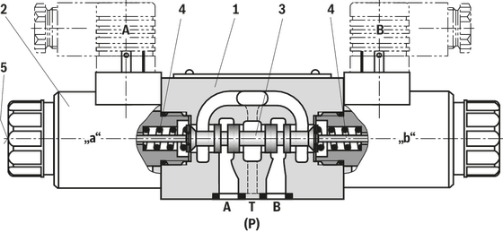
Directional valves type WE are solenoid-operated directional spool valves and can be used as electromagnetic components. They control the start, stop and direction of a flow.
The directional valves essentially consist of the housing (1), one or two electromagnets (2), the control spool (3) and the return springs (4).
In the de-energized state, the control spool (3) is held in the middle or initial position by the return springs (4) (except version “O”).
When the electromagnet (2) switching in oil is energized, the control spool (3) moves from its rest position to the desired end position. This releases the required flow direction according to the selected symbol.
After switching off the electromagnet (2), the control spool (3) is pushed back to the middle or initial position (except for valve with detent “OF” and valve without spring type “O”).
An auxiliary actuation (5) enables the valve to be switched manually without magnet supply.
The hydraulic system must be properly vented to ensure proper function.
Without spring return “O” (only possible with symbols A, C and D)
This version is a directional valve with two switching positions and two electromagnets without detent. The valve without spring return on the control spool (3) has no defined basic position when de-energized.
Without spring return with detent “OF” (only possible for symbols A, C and D)
This version is a directional valve with two switching positions and two electromagnets with detent. The control spool (3) is fixed in the respective switching position by the detents. During operation, the permanent current supply to the electromagnet can thus be omitted, which contributes to energy-efficient operation.
Version “.73...A12” (soft switching behavior)
The composition of the control spools and solenoids greatly reduces the number of switching strokes that occur when the valves are switched on or off. The switching strokes, measured as acceleration values a, can be reduced by approx. 85 % compared to the standard valve, depending on the version of the control spool (see “Acceleration values”).
Notices:
Pressure peaks in the drain line to two or more valves may cause unintentional control spool movements in the version with detent. It is recommended to lay separate return lines or to install a check valve in the drain line.
Due to the design principle, the valves are subject to internal leakage, which can increase during the service life.
Type 4WE 6 E6X/...E...
Throttle insert
The use of a throttle insert is required when, due to prevailing operating conditions, flows occur during the switching processes which exceed the performance limit of the valve.
01 | 02 | 03 | 04 | 05 | 06 | 07 | 08 | 09 | 10 | 11 | 12 | 13 | 14 | 15 | 16 | 17 | 18 | 19 | 20 | 21 | ||
WE | 6 | 6X | / | E | / | * |
01 | 3 main ports | 3 | ||||||||
4 main ports | 4 | |||||||||
02 | Directional valve | WE | ||||||||
03 | Size 6 | 6 | ||||||||
04 | Symbols; for the possible version, see "Symbols/Circuit diagrams" | |||||||||
05 | Component series 60 … 69 (60 … 69: unchanged installation and connection dimensions) | 6X | ||||||||
06 | With spring return | no code | ||||||||
Without spring return | O | |||||||||
Without spring return with detent | OF | |||||||||
07 | High-power solenoid, wet-pin, with detachable coil | E | ||||||||
Electrical voltages | ||||||||||
08 | For ordering code see "Electrical connections and available voltages" below. | e.g. G24 | ||||||||
Manual override 1) | ||||||||||
09 | Without manual override | no code | ||||||||
With manual override | N 3) | |||||||||
With manual override "mushroom button" (small) | N2 3) | |||||||||
With lockable manual override "mushroom button" (small) | N4 2; 3) | |||||||||
With lockable manual override "mushroom button" (large) | N5 2); 3; 4) | |||||||||
With manual override "mushroom button" (large), not lockable | N6 3; 4) | |||||||||
With lockable manual override "nut" | N72; 3) | |||||||||
With concealed manual override (standard) | N9 | |||||||||
Corrosion resistance (outside) (for the availability, refer to the following table) | ||||||||||
10 | None (valve housing primed) | no code | ||||||||
Improved corrosion protection (240 h salt spray test according to EN ISO 9227) | J3 | |||||||||
High corrosion protection (720 h salt spray test according to EN ISO 9227) | J5 | |||||||||
Electrical connection | ||||||||||
11 | Individual connection or central connection | |||||||||
For ordering code see "Electrical connections and available voltages" below. | e.g. K4 | |||||||||
Spool position monitoring (For more information, see data sheet 24830) | ||||||||||
12 | Without position switch | no code | ||||||||
Inductive position switch type QM (valves with 2 spool positions) | ||||||||||
Monitored spool position "a" | QMAG24 | |||||||||
Monitored spool position "b" | QMBG24 | |||||||||
Monitored rest position | QM0G24 | |||||||||
Inductive position switch type QR (valves with 3 spool positions) | ||||||||||
Monitored rest position | QM0G24 | |||||||||
Monitored spool position "a" and "b" | QRABG24E | |||||||||
Inductive position switch type QS | ||||||||||
Monitored spool position "a" | QSAG24W | |||||||||
Monitored spool position "b" | QSBG24W | |||||||||
Monitored spool position "0" | QS0G24W | |||||||||
Monitored spool position "0" and "a" | QS0AG24W | |||||||||
Monitored spool position "0" and "b" | QS0BG24W | |||||||||
Monitored spool position "a" and "b" | QSABG24W | |||||||||
Switching time increase | ||||||||||
13 | Without switching time increase | no code | ||||||||
With switching time increase (only with direct voltage and only with version "N9" and symbol "73") | A12 | |||||||||
Throttle insert | ||||||||||
14 | Without throttle insert (standard) | no code | ||||||||
With throttle insert (when the admissible valve performance limit is exceeded, refer to "Performance limits"): | ||||||||||
Connection | Throttle Ø in mm | |||||||||
0,6 mm | 0,8 mm | 1,0 mm | 1,2 mm | 1,5 mm | 2,0 mm | 2,5 mm | 3,0 mm | 4,0 mm | ||
P | = B06 | = B08 | = B10 | = B12 | = B15 | = B20 | = B25 | = B30 | = B40 | |
A | = H06 | = H08 | = H10 | = H12 | = H15 | = H20 | = H25 | = H30 | = H40 | |
B | = R06 | = R08 | = R10 | = R12 | = R15 | = R20 | = R25 | = R30 | = R40 | |
A and B | = N06 | = N08 | = N10 | = N12 | = N15 | = N20 | = N25 | = N30 | = N40 | |
T | = X06 | = X08 | = X10 | = X12 | = X15 | = X20 | = X25 | = X30 | = X40 | |
Clamping length | ||||||||||
15 | 42 mm (standard) | no code | ||||||||
22 mm | Z | |||||||||
Control spool play | ||||||||||
16 | Standard (recommended) | no code | ||||||||
Minimum (selection for reduced leakage values; higher oil cleanliness required) | T06 | |||||||||
Increased (selection with high temperature difference hydraulic fluid/environment; leads to higher internal leakage values) | T12 | |||||||||
Seal material (observe compatibility of seals with hydraulic fluid used, see "Technical data") | ||||||||||
17 | NBR seals | no code | ||||||||
FKM seals | V | |||||||||
Recommended for operation with HFC hydraulic fluids together with high temperatures | MH | |||||||||
Low-temperature version (only with version "Without manual override") | MT | |||||||||
18 | Standard | no code | ||||||||
Solenoid coil as approved component with UR marking according to UL 906, edition 1982 5) | = UR | |||||||||
Approval according to CSA C22.2 no. 139-1982 | = CSA | |||||||||
Porting pattern according to ANSI B93.9 6) | = AN | |||||||||
19 | Without locating hole | no code | ||||||||
With locating hole and locking pin ISO 8752-3x8-St | /62 | |||||||||
20 | Standard | no code | ||||||||
With reduced electric power consumption (only versions "G24" as well as "K4", "DL" and "DKL") | SO407 | |||||||||
21 | Further details in the plain text | * | ||||||||
| 1) | Operation of the manual override only possible up to 50 bar [725 psi] tank pressure. Avoid damage to the bore of the manual override. (Special tool for the operation, separate order, material no. R900024943). If the manual override is blocked, operation of the opposite solenoid is to be excluded. The manual override cannot be allocated a safety function. |
| 2) | With tank pressures higher than 50 bar, it is not guaranteed that the valve remains in the position into which it was switched by the lockable manual override ("N4", "N5", "N7"). |
| 3) | Only direct voltage; not for version "= UR" |
| 4) | Only direct voltage; not for version "SO407" |
| 5) | Only for version "K4" with "G12", "G24" and "W110" |
| 6) | With power supply to - solenoid "a", channel P is connected to a - solenoid "b", channel P is connected to B |
Electrical connection | Manual override | ||||||||
"K4" | "DL" | "K40", "C4" | |||||||
"G12" | "G24" | "G24" | "G48" | "G12" | "G24" | "G26" | Ohne | "N" | |
"J3" | ✔ | ✔ | ✔ | ✔ | - | - | - | ✔ | ✔ |
"J5" | - | - | - | - | ✔ | ✔ | ✔ | ✔ | ✔ |
(special voltages upon request)
Connector | Ordering code | Electrical voltages | Protection class according to EN 60529 1) | Protection class according to VDE 0580 | |||||||||
12 V | 24 V | 26 V | 48 V | 96 V | 110 V | 125 V | 205 V | 220 V | |||||
Ordering code | |||||||||||||
G12 | G24 | G26 | G48 | G96 | G110 | G125 | G205 | G220 | |||||
3-pole connector (2+PE) according to DIN EN 175301-803 |
| K4 | ✔ | ✔ | - | ✔ | ✔ | ✔ | ✔ | ✔ | ✔ | IP65 | I 2) |
| K4K | ✔ | ✔ | ✔ | - | - | - | - | - | - | IP65 | I 2) | |
Connector 2-pole, DT04-2PA (Deutsch type) | K40 | ✔ | ✔ | ✔ | - | - | - | - | - | - | IP65 | III 3) | |
Connector, 4-pole, M12x1 according to DIN EN 61076-2-101, with suppressor diode, coding A |
| K72L | - | ✔ | - | - | - | - | - | - | - | IP65 | III 3) |
| K73L | - | ✔ | - | - | - | - | - | - | - | IP65 | III 3) | |
Connector 2-pole (Junior-Timer type) |
| C4 | ✔ | ✔ | ✔ | - | - | - | - | - | - | IP65 | III 3) |
Maximum admissible overvoltages according to DIN EN 60664-1:2008-01 (VDE 0110-1) (overvoltage category II): | |||||||||||||
Nominal voltage UNom | V | 12 | 24 | 26 | 48 | 96 | 110 | 125 | 205 | 220 | |||
Rated current INom | A | 2,5 | 1,25 | 1,17 | 0,66 | 0,33 | 0,25 | 0,17 | 0,16 | 0,14 | |||
Maximum admissible switch-off overvoltage according to VDE 0580 | V | 500 | 500 | 500 | 500 | 500 | 500 | 500 | 500 | 500 | |||
Recommended interference protection circuit with 2 x mains voltage | V | 24 | 48 | 52 | 96 | 192 | 220 | 250 | 410 | 440 | |||
| 1) | Only with correctly mounted valve with a mating connector suitable for the protection class. |
| 2) | Protection class I with properly connected protective grounding conductor (PE) and valve mounting surface connected to the protective grounding conductor system. |
| 3) | With protection class III, a protective extra-low voltage with isolation transformer (PELV, SELV) is to be provided. |
Notice:
Solenoid valves induce voltage peaks during switch-off. In order to prevent electro-magnetic interference at the system and damage to the valve control, an interference protection circuit has to be provided on the system side. Alternatively, you can also select a connector with integrated interference protection circuit.
Connector | Ordering code | Electrical voltages | Protection class according to EN 60529 1) | Protection class according to VDE 0580 | |||||||
12 V | 24 V | 48 V | 96 V | 110 V | 125 V | 220 V | |||||
Ordering code | |||||||||||
G12 | G24 | G48 | G96 | G110 | G125 | G220 | |||||
Cable gland, terminal area 6 … 12 mm | With indicator light | DL | ✔ | ✔ | ✔ | ✔ | ✔ | ✔ | ✔ | IP65 | I 2) |
With indicator light and interference protection circuit | DL1 | ✔ | ✔ | ✔ | ✔ | ✔ | ✔ | ✔ | IP65 | I 2) | |
Cable gland, threaded connection 1/2"-14 NPT | With indicator light | DAL | ✔ | ✔ | - | - | - | ✔ | - | IP65 | I 2) |
With indicator light and interference protection circuit | DAL1 | ✔ | ✔ | - | - | - | ✔ | - | IP65 | I 2) | |
7-pole connector (6+PE) according to DIN EN 175201-804 | With indicator light | DK6L | - | ✔ | ✔ | - | ✔ | ✔ | ✔ | IP65 | I 2) |
With indicator light and interference protection circuit | DK6L1 | - | ✔ | ✔ | - | ✔ | ✔ | ✔ | IP65 | I 2) | |
Connector according to ANSI/B93.55M-1981 (Brad Harrison Mini-Change) | With indicator light, 3-pole | DK23L | - | ✔ | - | - | - | - | - | IP65 | I 2) |
With indicator light, 5-pole | DK25L | - | ✔ | - | - | - | - | - | IP65 | I 2) | |
Connector, 4-pole, M12x1 according to DIN EN 61076-2-101 | With indicator light | DK24L | - | ✔ | - | - | - | - | - | IP65 | III 3) |
With indicator light and interference protection circuit | DK24L1 | - | ✔ | - | - | - | - | - | IP65 | III 3) | |
With indicator light and interference protection circuit | DK35L | - | ✔ | - | - | - | - | - | IP65 | III 3) | |
Maximum admissible overvoltages according to DIN EN 60664-1:2008-01 (VDE 0110-1) (overvoltage category II): | |||||||||||
Nominal voltage UNom | V | 12 | 24 | 48 | 96 | 110 | 125 | 220 | |||
Rated current INom | A | 2,5 | 1,25 | 0,66 | 0,33 | 0,25 | 0,17 | 0,14 | |||
Maximum admissible switch-off overvoltage according to VDE 0580 | V | 500 | 500 | 500 | 500 | 500 | 500 | 500 | |||
Recommended interference protection circuit with 2 x mains voltage | V | 24 | 48 | 96 | 192 | 220 | 250 | 440 | |||
| 1) | Only with correctly mounted valve with a mating connector suitable for the protection class. |
| 2) | Protection class I with properly connected protective grounding conductor (PE) and valve mounting surface connected to the protective grounding conductor system. |
| 3) | With protection class III, a protective extra-low voltage with isolation transformer (PELV, SELV) is to be provided. |
Notice:
Solenoid valves induce voltage peaks during switch-off. In order to prevent electro-magnetic interference at the system and damage to the valve control, an interference protection circuit has to be provided on the system side. Alternatively, you can also select a connector with integrated interference protection circuit.
Connector | Ordering code | Electrical voltages | Protection class according to EN 60529 1) | Protection class according to VDE 0580 | ||||||||||
100 V 50/60 Hz | 100 V 50/60 Hz | 110 V 50/60 Hz | 110 V 50/60 Hz | 120 V 60 Hz | 120 V 60 Hz | 200 V 50 Hz | 200 V 50 Hz | 230 V 50/60 Hz | 230 V 50/60 Hz | |||||
Ordering code | ||||||||||||||
G96 | W110 | G96 | W110 | G110 | W110 | G180 | W200 | G205 | W230 | |||||
3-pole connector (2+PE) according to DIN EN 175301-803 | Standard | K4 | ✔ | ✔ | ✔ | ✔ | ✔ | ✔ | ✔ | ✔ | ✔ | ✔ | IP65 | I 2) |
Rectifier required (see "Accessories") | ✔ | ✔ | ✔ | - | ✔ | - | ✔ | - | ✔ | - | ||||
Maximum admissible overvoltages according to DIN EN 60664-1:2008-01 (VDE 0110-1) (overvoltage category II): | ||||||||||||||
Nominal voltage UNom | V | 100 | 100 | 110 | 110 | 120 | 120 | 200 | 200 | 230 | 230 | |||
Rated current INom |
| A | 0,31 | 0,56 | 0,34 | 0,52 | - | - | 0,18 | 0,29 | 0,16 | 0,23 | ||
| A | 0,31 | 0,44 | 0,34 | 0,39 | 0,30 | 0,45 | - | - | 0,16 | 0,17 | |||
Lower rated current |
| A | - | 0,65 | - | 0,6 | - | - | - | 0,33 | - | 0,27 | ||
| A | - | 0,51 | - | 0,45 | - | 0,52 | - | - | - | 0,2 | |||
Upper rated current |
| A | - | 0,9 | - | 0,9 | - | - | - | 0,6 | - | 0,36 | ||
| A | - | 0,9 | - | 0,6 | - | 0,9 | - | - | - | 0,36 | |||
Maximum admissible switch-off overvoltage according to VDE 0580 | V | 500 | 500 | 500 | 500 | 500 | 500 | 500 | 500 | 500 | 500 | |||
Recommended interference protection circuit with 2 x mains voltage | V | 200 | 200 | 220 | 220 | 240 | 240 | 400 | 400 | 460 | 460 | |||
| 1) | Only with correctly mounted valve with a mating connector suitable for the protection class. |
| 2) | Protection class I with properly connected protective grounding conductor (PE) and valve mounting surface connected to the protective grounding conductor system. |
Size |
6 | ||
Weight |
Valve with one solenoid |
kg |
1.45 |
Valve with two solenoids |
kg |
1.95 | |
Installation position |
any | ||
Ambient temperature range |
NBR seals |
°C |
-20 … +50 |
FKM seals |
°C |
-15 … +50 | |
Version for HFC hydraulic fluid |
°C |
-20 … +50 | |
Low-temperature version 1) |
°C |
-40 … +50 | |
Storage temperature range |
°C |
+5 … +40 | |
MTTFD values according to EN ISO 13849 2) |
Years |
300 | |
| 1) | For the use at low temperatures, see Project planning information |
| 2) | For further details, see data sheet 08012 |
Size |
6 | |||
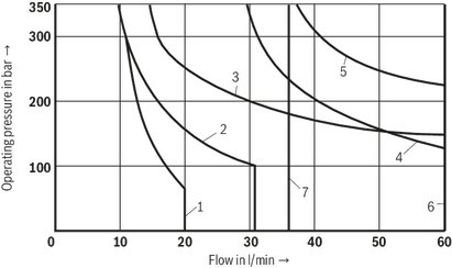
Maximum operating pressure |
Port P |
Standard version |
bar |
350 |
Version "SO407" |
bar |
315 | ||
Port A |
Standard version |
bar |
350 | |
Version "SO407" |
bar |
315 | ||
Port B |
Standard version |
bar |
350 | |
Version "SO407" |
bar |
315 | ||
Port T |
Direct voltage 1) |
bar |
210 | |
AC voltage 1) |
bar |
160 | ||
Maximum flow |
Direct voltage |
Standard version |
l/min |
80 |
Version "SO407" |
l/min |
60 | ||
AC voltage |
l/min |
60 | ||
Flow cross-section (spool position 0) |
Symbol Q |
approx. 6 % of nominal cross-section | ||
Symbol W |
approx. 3 % of nominal cross-section | |||
Hydraulic fluid |
see table "Hydraulic fluid" | |||
Hydraulic fluid temperature range |
NBR seals |
°C |
-20 … +80 | |
FKM seals |
°C |
-15 … +80 | ||
Version for HFC hydraulic fluid |
°C |
-20 … +50 | ||
Low-temperature version 2) |
°C |
-40 … +50 | ||
Viscosity range |
mm²/s |
2.8 … 500 | ||
Maximum admissible degree of contamination of the hydraulic fluid, cleanliness class according to ISO 4406 (c) 3) |
Class 20/18/15 | |||
| 1) | With symbols A and B, port T must be used as leakage oil connection if the operating pressure exceeds the admissible tank pressure. |
| 2) | For the use at low temperatures, see Project planning information |
| 3) | The cleanliness classes specified for the components must be adhered to in hydraulic systems. Effective filtration prevents faults and simultaneously increases the life cycle of the components. For the selection of the filters, see www.boschrexroth.com/filter. |
Hydraulic fluid |
Classification |
Suitable sealing materials |
Standards |
Data sheet |
|
Mineral oils |
HL, HLP, HLPD, HVLP, HVLPD |
NBR, FKM |
DIN 51524 |
90220 |
|
Bio-degradable |
Insoluble in water |
HETG |
FKM |
ISO 15380 |
90221 |
HEES |
FKM |
||||
Soluble in water |
HEPG |
FKM |
ISO 15380 |
||
Flame-resistant |
Water-free |
HFDU (glycol base) |
FKM |
ISO 12922 |
90222 |
HFDU (ester base) |
FKM |
||||
HFDR |
FKM |
||||
Containing water |
HFC (Fuchs: Hydrotherm 46M, Renosafe 500; |
NBR |
ISO 12922 |
90223 |
|
Important information on hydraulic fluids:
|
|||||
Voltage type |
Direct voltage | AC voltage 50/60 Hz | |||
Nominal voltage according to VDE 0580 |
See "Type codes" | ||||
Voltage tolerance (nominal voltage) |
% |
± 10 | |||
Nominal power according to VDE 0580 |
Standard version |
W |
30 | - | |
Version "SO407" |
W |
8 | - | ||
Version "= UR" |
W |
34 | - | ||
Holding power |
VA |
- | 50 | ||
Switch-on power |
VA |
- | 220 | ||
Duty cycle |
100% (S1 according to VDE 0580) | ||||
Switching time according to ISO 6403 1) |
ON |
ms |
25 … 45 | 10 … 20 | |
OFF |
ms |
10 … 25 | 15 … 40 | ||
Maximum switching frequency |
Standard version |
1/s |
4.2 | 2 | |
Version "SO407" |
1/s |
2 | - | ||
Maximum surface temperature of the coil 2) |
Standard version |
°C |
120 | 180 | |
Version "SO407" |
°C |
85 | - | ||
Version "= UR" |
°C |
120 | - | ||
Insulation class VDE 0580 |
Standard |
F | H | ||
Version "= UR" |
Version "G12", "G24" |
F | |||
Version "G110", "W120R" |
H | ||||
Protection class according to EN 60529 |
See "Type codes" | ||||
Protection class according to VDE 0580 |
See "Type codes" | ||||
Electrical fuse protection |
Maximum admissible switch-off overvoltage see "Type codes". Every solenoid must be protected individually, using a suitable fuse with tripping characteristics K (inductive loads). |
||||
Protective earthing conductor and screening |
The valve must be installed on a surface that is included in the equipotential bonding. Connector pin assignment (CE-compliant installation) see "Electrical connection". |
||||
Conformity |
CE according to Low-Voltage Directive 2014/35/EU checked according to EN 60204-1:2006-01 and DIN VDE 0580, classified as component. | ||||
| 1) | Measured without flow. The switching times were determined for a hydraulic fluid temperature of 40 °C and a viscosity of 46 mm2/s. Switching times change dependent on hydraulic fluid temperatures, operating time and application conditions. |
| 2) | Due to the temperatures occurring at the surfaces of the solenoid coils, the standards ISO 13732-1 and ISO 4413 need to be adhered to!The specified surface temperature in AC solenoids is valid for fault-free operation. In the error case (e.g. blocking of the control spool), the surface temperature may increase above 180 °C. Thus, the system must be checked for possible dangers considering the ignition temperature of the hydraulic fluid used. As fuse protection, circuit breakers must be used, unless the creation of an ignitable atmosphere can be excluded in a different way. In this way, the surface temperature in an error case can be limited to a maximum of 220 °C. You have to use cables that have been approved of for a working temperature of more than 50 °C (individual connection) and/or 90 °C (central connection). |
Notices:
The solenoid coils must not be painted.
Any simultaneous actuation of 2 solenoids of one valve must be ruled out.
Fast switch-on
For accelerated switching on the solenoid side, valves with individual connection and a nominal voltage of 12 V or 24 V can be controlled with two times the voltage for a maximum of 100 ms (pulse width modulation see data sheet 30362). In this connection, the maximum admissible switching frequency is reduced to 3 1/s.
Dampened switching
With valves of version "A12", damping of the switch-on and switch-off process is possible (smoothly switching). In this way, switching shocks in the system are considerably reduced.

Size |
6 | ||
Weight |
Valve with one solenoid |
kg |
1.45 |
Valve with two solenoids |
kg |
1.95 | |
Installation position |
any | ||
Ambient temperature range |
NBR seals |
°C |
-20 … +50 |
FKM seals |
°C |
-15 … +50 | |
Version for HFC hydraulic fluid |
°C |
-20 … +50 | |
Low-temperature version 1) |
°C |
-40 … +50 | |
Storage temperature range |
°C |
+5 … +40 | |
MTTFD values according to EN ISO 13849 2) |
Years |
300 | |
| 1) | For the use at low temperatures, see Project planning information |
| 2) | For further details, see data sheet 08012 |
Size |
6 | |||
Maximum operating pressure |
Port P |
Standard version |
bar |
350 |
Version "SO407" |
bar |
315 | ||
Port A |
Standard version |
bar |
350 | |
Version "SO407" |
bar |
315 | ||
Port B |
Standard version |
bar |
350 | |
Version "SO407" |
bar |
315 | ||
Port T |
Direct voltage 1) |
bar |
210 | |
AC voltage 1) |
bar |
160 | ||
Maximum flow |
Direct voltage |
Standard version |
l/min |
80 |
Version "SO407" |
l/min |
60 | ||
AC voltage |
l/min |
60 | ||
Flow cross-section (spool position 0) |
Symbol Q |
approx. 6 % of nominal cross-section | ||
Symbol W |
approx. 3 % of nominal cross-section | |||
Hydraulic fluid |
see table "Hydraulic fluid" | |||
Hydraulic fluid temperature range |
NBR seals |
°C |
-20 … +80 | |
FKM seals |
°C |
-15 … +80 | ||
Version for HFC hydraulic fluid |
°C |
-20 … +50 | ||
Low-temperature version 2) |
°C |
-40 … +50 | ||
Viscosity range |
mm²/s |
2.8 … 500 | ||
Maximum admissible degree of contamination of the hydraulic fluid, cleanliness class according to ISO 4406 (c) 3) |
Class 20/18/15 | |||
| 1) | With symbols A and B, port T must be used as leakage oil connection if the operating pressure exceeds the admissible tank pressure. |
| 2) | For the use at low temperatures, see Project planning information |
| 3) | The cleanliness classes specified for the components must be adhered to in hydraulic systems. Effective filtration prevents faults and simultaneously increases the life cycle of the components. For the selection of the filters, see www.boschrexroth.com/filter. |
Hydraulic fluid |
Classification |
Suitable sealing materials |
Standards |
Data sheet |
|
Mineral oils |
HL, HLP, HLPD, HVLP, HVLPD |
NBR, FKM |
DIN 51524 |
90220 |
|
Bio-degradable |
Insoluble in water |
HETG |
FKM |
ISO 15380 |
90221 |
HEES |
FKM |
||||
Soluble in water |
HEPG |
FKM |
ISO 15380 |
||
Flame-resistant |
Water-free |
HFDU (glycol base) |
FKM |
ISO 12922 |
90222 |
HFDU (ester base) |
FKM |
||||
HFDR |
FKM |
||||
Containing water |
HFC (Fuchs: Hydrotherm 46M, Renosafe 500; |
NBR |
ISO 12922 |
90223 |
|
Important information on hydraulic fluids:
|
|||||
Voltage type |
Direct voltage | AC voltage 50/60 Hz | |||
Nominal voltage according to VDE 0580 |
See "Type codes" | ||||
Voltage tolerance (nominal voltage) |
% |
± 10 | |||
Nominal power according to VDE 0580 |
Standard version |
W |
30 | - | |
Version "SO407" |
W |
8 | - | ||
Version "= UR" |
W |
34 | - | ||
Holding power |
VA |
- | 50 | ||
Switch-on power |
VA |
- | 220 | ||
Duty cycle |
100% (S1 according to VDE 0580) | ||||
Switching time according to ISO 6403 1) |
ON |
ms |
25 … 45 | 10 … 20 | |
OFF |
ms |
10 … 25 | 15 … 40 | ||
Maximum switching frequency |
Standard version |
1/s |
4.2 | 2 | |
Version "SO407" |
1/s |
2 | - | ||
Maximum surface temperature of the coil 2) |
Standard version |
°C |
120 | 180 | |
Version "SO407" |
°C |
85 | - | ||
Version "= UR" |
°C |
120 | - | ||
Insulation class VDE 0580 |
Standard |
F | H | ||
Version "= UR" |
Version "G12", "G24" |
F | |||
Version "G110", "W120R" |
H | ||||
Protection class according to EN 60529 |
See "Type codes" | ||||
Protection class according to VDE 0580 |
See "Type codes" | ||||
Electrical fuse protection |
Maximum admissible switch-off overvoltage see "Type codes". Every solenoid must be protected individually, using a suitable fuse with tripping characteristics K (inductive loads). |
||||
Protective earthing conductor and screening |
The valve must be installed on a surface that is included in the equipotential bonding. Connector pin assignment (CE-compliant installation) see "Electrical connection". |
||||
Conformity |
CE according to Low-Voltage Directive 2014/35/EU checked according to EN 60204-1:2006-01 and DIN VDE 0580, classified as component. | ||||
| 1) | Measured without flow. The switching times were determined for a hydraulic fluid temperature of 40 °C and a viscosity of 46 mm2/s. Switching times change dependent on hydraulic fluid temperatures, operating time and application conditions. |
| 2) | Due to the temperatures occurring at the surfaces of the solenoid coils, the standards ISO 13732-1 and ISO 4413 need to be adhered to!The specified surface temperature in AC solenoids is valid for fault-free operation. In the error case (e.g. blocking of the control spool), the surface temperature may increase above 180 °C. Thus, the system must be checked for possible dangers considering the ignition temperature of the hydraulic fluid used. As fuse protection, circuit breakers must be used, unless the creation of an ignitable atmosphere can be excluded in a different way. In this way, the surface temperature in an error case can be limited to a maximum of 220 °C. You have to use cables that have been approved of for a working temperature of more than 50 °C (individual connection) and/or 90 °C (central connection). |
Notices:
The solenoid coils must not be painted.
Any simultaneous actuation of 2 solenoids of one valve must be ruled out.
Fast switch-on
For accelerated switching on the solenoid side, valves with individual connection and a nominal voltage of 12 V or 24 V can be controlled with two times the voltage for a maximum of 100 ms (pulse width modulation see data sheet 30362). In this connection, the maximum admissible switching frequency is reduced to 3 1/s.
Dampened switching
With valves of version "A12", damping of the switch-on and switch-off process is possible (smoothly switching). In this way, switching shocks in the system are considerably reduced.
4 |
Symbol "H" in central position P – T |
7 |
Symbol „R“ in spool position B – A |
8 |
Symbol „G“ and „T“ in central position P ‒ T |
Symbol |
Direction of flow |
|||
P-A |
P-B |
A-T |
B-T |
|
A; B |
5 |
5 |
– |
– |
C; C46 |
3 |
3 |
5 |
3 |
D; D46; Y |
6 |
6 |
5 |
5 |
E |
5 |
5 |
3 |
3 |
F |
3 |
5 |
3 |
3 |
T |
8 |
8 |
4 |
4 |
H |
2 |
1 |
2 |
2 |
J; Q |
3 |
3 |
2 |
3 |
L |
5 |
5 |
1 |
4 |
M |
2 |
1 |
5 |
5 |
P |
5 |
3 |
3 |
3 |
R |
6 |
6 |
1 |
‒ |
V |
3 |
2 |
3 |
3 |
W |
3 |
3 |
2 |
2 |
U |
5 |
5 |
4 |
1 |
G |
7 |
7 |
4 |
4 |
Symbol |
Direction of flow |
|||||
P-A |
P-B |
A-T |
B-T |
P-T |
B-A |
|
E73 |
11 |
11 |
11 |
11 |
– |
– |
J73 |
13 |
13 |
9 |
9 |
– |
– |
H73 |
11 |
11 |
11 |
11 |
12 |
– |
A73; B73 |
15 |
15 |
– |
– |
– |
– |
D73; Y73 |
14 |
14 |
14 |
14 |
– |
– |
G73 |
16 |
16 |
16 |
16 |
12 |
– |
R73 |
10 |
15 |
10 |
– |
– |
15 |
W73 |
10 |
10 |
10 |
10 |
– |
– |
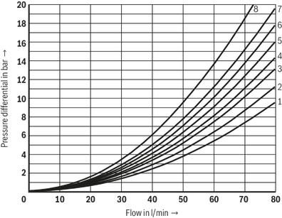
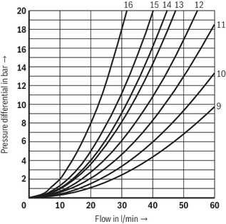
(measured with HLP46, ϑOil = 40 ±5 °C)
Notice:
The specified performance limits are valid for operation with two directions of flow (e.g. from P to A and simultaneous return flow from B to T).
Due to the flow forces acting within the valves, the possible performance limit may be considerably lower with only one direction of flow (e.g. from P to A while port B is blocked).
The performance limits were determined when the solenoids were at operating temperature, at 10% undervoltage and without tank preloading.
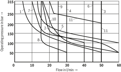
Standard version

Characteristic curve |
Symbol |
1 |
A; B1) |
2 |
V |
3 |
A; B |
4 |
F; P |
5 |
J |
6 |
G; H; T; |
7 |
A/O; A/OF; L; U |
8 |
C; D; Y |
9 |
M |
10 |
E; E1?2); R3); C/O; C/OF; D/O; D/OF; Q; W |
| 1) | With manual override |
| 2) | P – A/B pre-opening |
| 3) | Return flow from actuator to tank |
Version "A12"
Characteristic curve |
Symbol |
1 |
A73; B73 |
2 |
G73 |
3 |
D73; Y73 |
4 |
J73 |
5 |
R73 |
6 |
E73; W73; D73/OF |
7 |
H73 |
Version "SO407"
Characteristic curve |
Symbol |
1 |
A |
2 |
C; D; Y |
3 |
M |
4 |
G |
5 |
E |
6 |
H |
7 |
J |
8 |
V |
9 |
T |
10 |
R 1) |
11 |
C46/OF; D46/OF |
| 1) | Return flow from actuator to tank |
Standard version
Characteristic curve |
Symbol |
1 |
A; B 1) |
2 |
V |
3 |
A; B |
4 |
F; P |
5 |
G; T |
6 |
H |
7 |
C/O; C/OF; D/O; D/OF; E; E1-2); J; M; R3) |
8 |
C; D; Y |
9 |
J; L; U |
10 |
A/O; A/OF; Q; W |
| 1) | With manual override |
| 2) | P – A/B pre-opening |
| 3) | Return flow from actuator to tank |
4 |
Symbol "H" in central position P – T |
7 |
Symbol „R“ in spool position B – A |
8 |
Symbol „G“ and „T“ in central position P ‒ T |
Symbol |
Direction of flow |
|||
P-A |
P-B |
A-T |
B-T |
|
A; B |
5 |
5 |
– |
– |
C; C46 |
3 |
3 |
5 |
3 |
D; D46; Y |
6 |
6 |
5 |
5 |
E |
5 |
5 |
3 |
3 |
F |
3 |
5 |
3 |
3 |
T |
8 |
8 |
4 |
4 |
H |
2 |
1 |
2 |
2 |
J; Q |
3 |
3 |
2 |
3 |
L |
5 |
5 |
1 |
4 |
M |
2 |
1 |
5 |
5 |
P |
5 |
3 |
3 |
3 |
R |
6 |
6 |
1 |
‒ |
V |
3 |
2 |
3 |
3 |
W |
3 |
3 |
2 |
2 |
U |
5 |
5 |
4 |
1 |
G |
7 |
7 |
4 |
4 |
Symbol |
Direction of flow |
|||||
P-A |
P-B |
A-T |
B-T |
P-T |
B-A |
|
E73 |
11 |
11 |
11 |
11 |
– |
– |
J73 |
13 |
13 |
9 |
9 |
– |
– |
H73 |
11 |
11 |
11 |
11 |
12 |
– |
A73; B73 |
15 |
15 |
– |
– |
– |
– |
D73; Y73 |
14 |
14 |
14 |
14 |
– |
– |
G73 |
16 |
16 |
16 |
16 |
12 |
– |
R73 |
10 |
15 |
10 |
– |
– |
15 |
W73 |
10 |
10 |
10 |
10 |
– |
– |
(measured with HLP46, ϑOil = 40 ±5 °C)
Notice:
The specified performance limits are valid for operation with two directions of flow (e.g. from P to A and simultaneous return flow from B to T).
Due to the flow forces acting within the valves, the possible performance limit may be considerably lower with only one direction of flow (e.g. from P to A while port B is blocked).
The performance limits were determined when the solenoids were at operating temperature, at 10% undervoltage and without tank preloading.
Standard version
Characteristic curve |
Symbol |
1 |
A; B1) |
2 |
V |
3 |
A; B |
4 |
F; P |
5 |
J |
6 |
G; H; T; |
7 |
A/O; A/OF; L; U |
8 |
C; D; Y |
9 |
M |
10 |
E; E1?2); R3); C/O; C/OF; D/O; D/OF; Q; W |
| 1) | With manual override |
| 2) | P – A/B pre-opening |
| 3) | Return flow from actuator to tank |
Version "A12"
Characteristic curve |
Symbol |
1 |
A73; B73 |
2 |
G73 |
3 |
D73; Y73 |
4 |
J73 |
5 |
R73 |
6 |
E73; W73; D73/OF |
7 |
H73 |
Version "SO407"
Characteristic curve |
Symbol |
1 |
A |
2 |
C; D; Y |
3 |
M |
4 |
G |
5 |
E |
6 |
H |
7 |
J |
8 |
V |
9 |
T |
10 |
R 1) |
11 |
C46/OF; D46/OF |
| 1) | Return flow from actuator to tank |
Standard version
Characteristic curve |
Symbol |
1 |
A; B 1) |
2 |
V |
3 |
A; B |
4 |
F; P |
5 |
G; T |
6 |
H |
7 |
C/O; C/OF; D/O; D/OF; E; E1-2); J; M; R3) |
8 |
C; D; Y |
9 |
J; L; U |
10 |
A/O; A/OF; Q; W |
| 1) | With manual override |
| 2) | P – A/B pre-opening |
| 3) | Return flow from actuator to tank |


